Operator Console Installation Manual
Purpose
This document gives instructions on installing the PathPilot Operator Console Assembly for 1100M/1100M+/1100MX.
Product Information
Product: PathPilot Operator Console Assembly for 1100M/1100M+/1100MX (PN 50440)
Quantity | Description |
1 | Access Panel |
1 | Controller Wire Kit (PN 50367) |
1 | Jog Pendant (PN 50363) |
1 | Keyboard Tray |
1 | Machine Controller |
1 | Mount Arm |
4 | Mount Arm Brackets |
5 | Plastic with Adhesive Backing |
18 | Screw with Washer, M5 × 0.8 - 10 |
10 | Screw with Washer, M4 × 0.7 - 10 |
4 | Split Collar |
NOTE: If any items are missing, we can help. Create a support ticket with Tormach Technical Support at tormach.com/how-to-submit-a-support-ticket for guidance on how to proceed.
Required Tools
This procedure requires the following tools. Collect them before you begin.
15/64 in. drill bit
Electric drill
Hole punch
Level
Metric hex wrench set
Phillips screwdriver
Phillips screwdriver, small
Scissors
Ruler
Tape
Before You Begin
Machine Arm Not Compatible If you already have a machine arm installed on your machine, you must first disassemble it. Refer to the product's documentation, and follow the steps in reverse order.
Machine Enclosure Required If you haven't yet done so, you must first install the machine's enclosure. See the product's documentation for more information.
Prepare the Machine
Power off the machine and the PathPilot controller.
Push in the machine's red Emergency Stop button, which removes power to motion control.
From the PathPilot interface, select Exit.
Turn the Main Disconnect switch to OFF on the side of the electrical cabinet.
Close the enclosure doors.
NOTICE! This procedure requires you to drill four holes into the enclosure. If the enclosure's right door is open, there's a risk that you'll drill into it.
Remove the Right Side Window
To make it easier to install the mount arm, we recommend removing the right side window from the enclosure. Loosen the screws on the vertical window retainers, and slide the window out of the right side panel. Set the window aside.
Remove the Operator Box
Remove the Emergency Stop cable from the operator box.
Remove the four screws that secure the operator box to the machine stand using a 3 mm hex wrench.
Discard the operator box.Put the four screws from the operator box back on to the machine stand.
Install the Mount Arm
Print the drill template provided in this document. To verify that the template printed at the correct size, use a ruler to measure the 1 in. scale on the template. If the template is incorrectly sized, adjust your printer settings and try again.
Cut out the drill template along its edges.
Find the operator console's mount arm.
Put the drill template on the mount arm's top bracket. Then, verify that the holes on the bracket align with the holes on the drill template. If they don't, trace the correct hole pattern on to the drill template.
Align the drill template to the top of the enclosure and tape it in place, as shown in the following image.
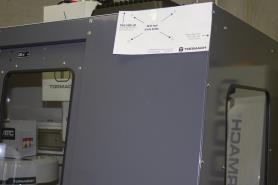
Figure 1: Drill template taped to the enclosure.
Put a mark in each hole on the drill template using a hole punch.
Remove the drill template from the enclosure and discard it.
Drill into the marks on the enclosure that you made in Step 6 using an electric drill and a 15/64 in. (6 mm) drill bit.
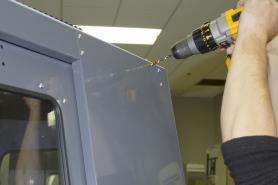
Figure 2: Drilling holes into the top of the enclosure.
Loosely secure the top of the mount arm to the enclosure with four M5 × 0.8 - 10 screws and washers.
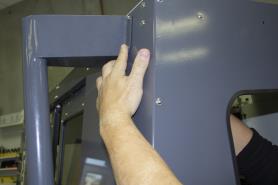
Figure 3: Securing the top of the mount arm to the enclosure.
Using a level, align the bottom of the mount arm with the bottom of the enclosure.
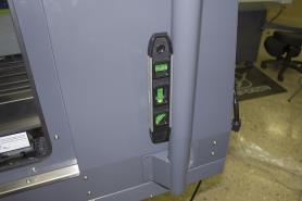
Figure 4: Bottom of the mount arm level on the enclosure.
Using the bottom of the mount arm as a template, drill one hole using an electric drill and a 15/64 in. drill bit.
Put one M5 × 0.8 - 10 screw and washer into the hole that you drilled in Step 11.
The mount arm is now secure enough to reliably drill the remaining three holes.Drill the remaining three holes for the mount arm's bottom bracket.
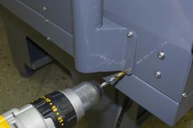
Figure 5: Drilling the remaining three holes into the enclosure.
Put three M5 × 0.8 - 10 screws and washers into the remaining three holes.
Once the mount arm is secured to the enclosure, open the enclosure door and verify that the mount arm's screws don't interfere with the enclosure door jamb. If they do, loosen the screws on the door jamb, and slide it toward the back of the machine.
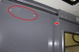
Figure 6: Door jamb moved to provide clearance for the mount arm's screws.
Mount the Console
Complete the following steps in the order listed:
Assemble the Controller and Keyboard Tray
Find the three provided split collars. If they're connected, remove their bolts using a 8 mm hex wrench, and separate them. The split collars are matched pairs, so you must keep them together.
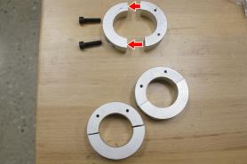
Figure 7: One split collar disassembled.
Find the four provided pieces of plastic with adhesive backing. Cut each piece of plastic so that it's the length of the inside of the split collar.
Adhere one piece of plastic to the inside of each split collar.

Figure 8: Adhering tape on the inside of a split collar.
Remove the operator console out of its packaging.
Find the three provided mount arm brackets.

Figure 9: Mount arm brackets.
Loosely attach two of the mount arm brackets to the left side of the controller with four M4 × 0.7 - 10 screws using a 2.5 mm hex wrench, as shown in the following image. Verify that the curved edge is facing away from the controller.
NOTE: Don't completely tighten the brackets to the controller. You'll adjust them when you're adjusting the height of the entire console assembly.
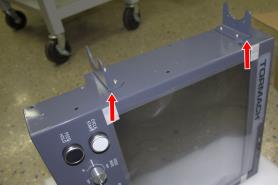
Figure 10: Two mount brackets attached to the controller.
Attach the threaded side of two split collars to the mount arm brackets with four M5 × 0.8 - 10 screws and washers.
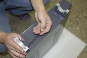
Figure 11: Split collars attached to the mount arm brackets on the controller.
Find the keyboard tray provided. Then, attach the remaining mount arm bracket to the left side of the keyboard tray with two M4 × 0.7 - 10 screws using a 2.5 mm hex wrench. Verify that the curved edge is facing away from the keyboard tray.
Attach one side of one split collar to the mount arm bracket with two M5 × 0.8 - 10 screws and washers.
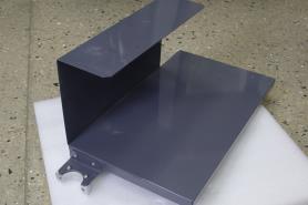
Figure 12: Split collar attached to the mount arm bracket on the keyboard tray.
Find the provided jog pendant bracket. Then, attach it to the left side of the controller (between the two mount arm brackets) with two M4 × 0.7 - 10 screws using a 2.5 mm hex wrench.
Set the keyboard tray aside.
Lift and Secure the Controller Assembly
Attach the remaining split collar to the mount arm, and completely tighten it using a 8 mm hex wrench. This split collar determines the height for the overall console assembly, so we suggest attaching it 16-1/2 in. (42 cm) from the top of the enclosure.

Figure 13: Split collar attached to the mount arm.
CAUTION! Team Lift Required: You must have the aid of more than one person to lift and move the object. The object is heavy, and lifting it by yourself can cause serious injury.
Lift the console and hold it on the right side of the mount arm.
Align the bottom split collar on the controller with the split collar that you installed on the mount arm in Step 1.
With the aid of another person, loosely attach the opposite side of both split collars to the mount arm using a 8 mm hex wrench.

Figure 14: Loosely attaching the split collars to the mount arm.
Find the keyboard tray that you set aside earlier. Then, attach it to the bottom of the controller, as shown in the following image.
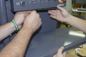
Figure 15: Attaching the keyboard tray to the bottom of the controller.
Loosely attach the opposite side of the split collar to the mounting arm using a 8 mm hex wrench.
Adjust the height and the angle of the console assembly as required.
Securely tighten all four split collars using a 8 mm hex wrench. Securely tighten all mount arm brackets using a 2.5 mm hex wrench.
Make Electrical Connections
Find the provided Jog Pendant (PN 50363).
Hang the jog pendant on its bracket (on the front of the controller) as shown in the following image.
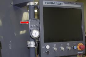
Figure 16: Jog pendant on the front of the console assembly.
Route the loose end of the jog pendant to the back of the controller.
Find the provided power supply bracket. Then, attach it to the back of the controller with two M3 screws using a Phillips screwdriver.
Find the provided power, Ethernet, emergency stop extension, and ATC USB extension cables, and the WiFi dongle. Then, connect them – and the jog pendant cable – to the controller as shown in the following image.
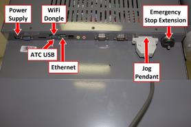
Figure 17: Controller connections.
Put the power supply into the power supply bracket.
Find the provided corrugated tubing and piece of rubber.
Attach the piece of rubber to the bracket on the rear of the keyboard tray as shown in the following image.
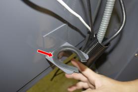
Figure 18: Rubber attached to the bracket on the keyboard tray.
Put the loose ends of all cables from the controller into the corrugated tubing.
Push the corrugated tubing into the bracket on the rear of the keyboard tray.
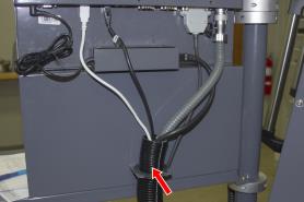
Figure 19: Cords put into corrugated tubing, which is attached to the rear of the keyboard tray.
Find the access panel on the machine stand as shown in the following image.
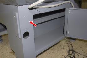
Figure 20: Access panel on the machine stand.
Remove the access panel using a 2 mm hex wrench, and discard the panel. Set the screws aside for later in this procedure.
Find the provided access panel. Then, put the loose end of the corrugated tubing and all cords through it as shown in the following image.
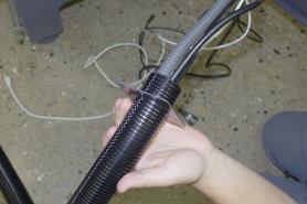
Figure 21: Loose end of corrugated tubing and all cords put through the access panel.
Attach the access panel – with the corrugated tubing and all cords – to the machine stand with the screws that you set aside in Step 12 using a 2 mm hex wrench.
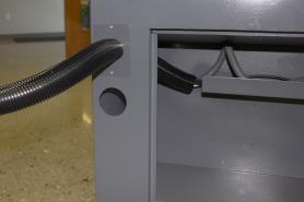
Figure 22: Access panel attached to the machine stand.
Route the loose end of all cords through the machine stand and out toward the rear of the machine.
Find the existing operator box cable that's preinstalled on the machine. Then, route it through the access hole in the machine stand shown in the following image.
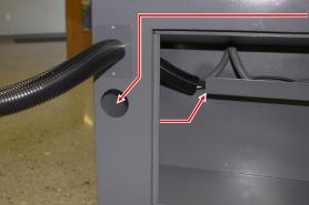
Figure 23: Preinstalled operator box cable routing.
Connect the operator box extension cable to the existing operator box cable (that you just routed into the machine stand).
Connect the Ethernet cable to the Controller Communications port on the side of the electrical cabinet.
Connect the power cable to the Accessory Power port on the rear of the electrical cabinet.
From the ATC, remove and discard the existing USB cable. Then, route the loose end of the ATC USB extension cable from the controller to the ATC, and connect it in place of the original USB cable.
If you have an EU model of the operator console, find the provided set of keys, and put it into the top of the operator console.
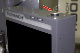
Figure 24: Key put into the controller.
NOTE: On EU machines, the keys switch between run mode and setup mode. If you don't have an EU machine, you don't need the keys. For more information on operation modes, refer to the Safety section of the EU machine operator's manual.
Reassemble the Machine
Put the right side window (that you set aside in "Prepare the Machine" (page 4)) back into the right side panel on the enclosure. Then, tighten the screws on the vertical window retainers
Power on the machine and the PathPilot controller.
Turn the Main Disconnect switch to ON on the side of the electrical cabinet.
Twist out the machine's red Emergency Stop button, which enables movement to the machine axes and the spindle.
Press the Reset button.
Bring the machine out of reset and reference it.
Troubleshooting
Problem
The touch screen does not respond to touch inputs on all or part of the screen's surface.
Cause
The sensitivity setting for the touch controller is too low.
Solutions
You Might Need To... | Probability | How-To Steps | Need More? |
Adjust touchscreen sensitivity. | High |
| The touchscreen is a resistive type to prevent accidental triggering from drops of coolant on the screen. The resistive touchscreen may need its sensitivity adjusted when used in a shop space with very high or low humidity. |
Problem
The console screen doesn't display an image or respond to the power button.
Cause
The console isn't receiving power.
Solutions
You Might Need To... | Probability | How-To Steps | Need More? |
Examine power input to the console. | High | Examine the green LED on the power brick for the console. If it's not lit, examine the power cords to the power brick. | If your console receives power from the Accessory Input ports on the machine, look for tripped breakers inside your machine's electrical cabinet. |
Test the power button functionality. | Low | Examine the green ring around the power button. It should light up when you press the power button. |
|
Problem
The console screen turns on, but is scrambled or illegible.
Cause
The BIOS isn't configured for the correct screen output.
Solutions
You Might Need To... | Probability | How-To Steps | Need More? |
Configure the display output settings in BIOS. | High |
| This configuration problem can occur if your console has a CMOS battery failure. Replace the battery if it reoccurs. |
Problem
The RPM, Feed Override, or Max Velocity knobs don't respond or aren't smooth.
Cause
The ribbon cable connecting the knobs is disconnected or the circuit board is damaged.
Solutions
You Might Need To... | Probability | How-To Steps | Need More? |
Examine the connectors on the ribbon cable. | High |
| Shipping can sometime cause connectors to become loose. Re-seating the connectors will usually fix non-responsive override knobs. |
Examine the USB connection to the control board. | High |
| Verify that the power LED on the console control board lights up when the console is turned on. If it doesn't light up, and you have confirmed the USB connection, replace the control board (PN 39146). |
Problem
The Cycle Start or Feed Hold buttons don't respond.
Cause
The control board is disconnected or the wires to the buttons are loose.
Solutions
You Might Need To... | Probability | How-To Steps | Need More? |
Examine the wiring to the buttons. | High |
| Shipping can sometime cause wire terminals to become loose. Re-seating the wires will usually fix non-responsive buttons. If you have tested all terminals and the buttons still don't have continuity when pressed, replace the buttons: Feed Hold Button (PN 37363) Cycle Start Button (PN 37362) |
Examine the USB connection to the control board. | High |
| Verify that the power LED on the console control board lights up when the console is turned on. If it doesn't light up and you have confirmed the USB connection, replace the control board (PN 39146). |
To view a PDF version of your manual, go to Tormach document TD10596.
If you have additional questions, we can help. Create a support ticket with Tormach Technical Support at tormach.com/how-to-submit-a-support-ticket for guidance on how to proceed.