Install the Controller Arm
The Controller Arm mounts to the right-hand side of the lathe stand. One of the two red Emergency Stop buttons mounts to the underside of the keyboard tray and should protrude past the edge of the tray far enough to be easily accessible.
IMPORTANT! If you set up the controller in a different configuration, you must make sure that the lathe’s remote Emergency Stop button is installed so that it is easily accessible to you.
To install the Controller Arm:
-
Identify the correct mounting position for the controller arm on the machine stand.
-
Make sure that there are no obstructions inside of the machine stand.
-
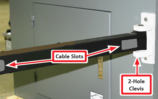
Use two sets of M8 x 30 mm socket head cap screws, M8 hex nuts, M8 flat washers, and M8 lock washers to attach the mounting clevis to the machine stand (see Figure 1). Make sure that the cable slots on the square tube arm are facing as shown in Figure 1.
-
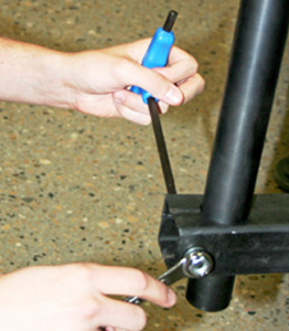
Insert the round monitor post into the square tube arm and tighten the cross bolt (see Figure 2). Make sure that the holes are along the inside of the round monitor post as shown in Figure 2.
NOTE: You can adjust the working height of the post the keyboard table and the monitor are attached.
-
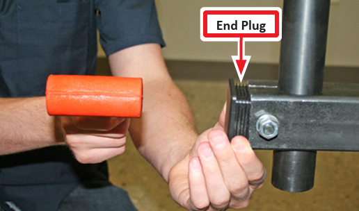
Use a dead-blow hammer (or similar) to tap the end plug into the square tube arm (see Figure 3).
-
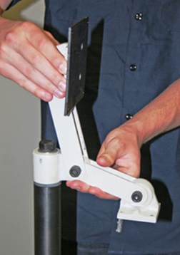
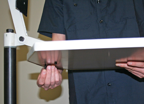
Position the round monitor post to mount the keyboard table as shown in Figure 4. Tighten the applicable screws to maintain the desired position.
-
Use four M5 x 25 mm socket head screws, four M5 flat washers, and four M5 lock washers to attach the keyboard table to the round monitor post (see Figure 5).
-
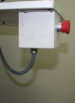
Use four M4 x 12 mm wood screws to attach the Emergency Stop box below the keyboard table (see Figure 6).
-
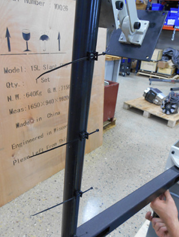
Use four M4 x 8 mm flat head screws to attach four wire tie mounts to the round monitor post (see Figure 7).
-
Use two M4 x 8 mm flat head screws to attach two Emergency Stop cable clips to the bottom of the square tube arm.
-
Use four M4 x 10 mm Phillips round head screws to attach the monitor, and then route the cables through the controller arm.
NOTE: We recommend wrapping all cable connections in electrical tape.
-
Adjust the monitor height and keyboard angle as needed.
Install the Monitor
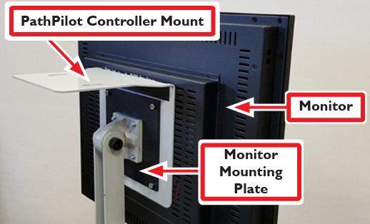
The PathPilot controller mount allows you to install the PathPilot controller behind the monitor (which is attached to the Controller Arm).
Note: If you’re using a Touch Screen Kit (PN 35575), you must first remove the stock mounting bracket from the back of the monitor.
-
Put the PathPilot controller mount against the monitor mounting plate. Then, put the monitor on the other side of the PathPilot controller mount, and align the holes on the three components.
-
Attach the monitor, PathPilot controller mount, and monitor mounting plate together with four M4 × 12 mm socket head cap screws (provided with the PathPilot controller mount).
-
Adjust the position of the monitor and the keyboard tray with an 8 mm hex wrench and a 16 mm wrench. Once complete, securely tighten the pivot screws.
Install the PathPilot Controller
The PathPilot controller attaches to the top of the PathPilot controller mount and behind the monitor.
-
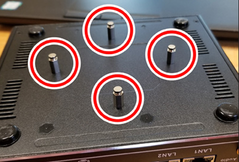
Put four standoffs into the controller and tighten them by hand (see Figure 9).
-
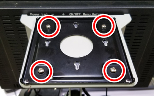
Find the four M4 screws and the VESA plate included with the controller. Then, mount the VESA plate to the PathPilot Controller VESA Mount (PN 50382). Make sure to put it flat side down with the keyholes toward the monitor (see Figure 10).
-
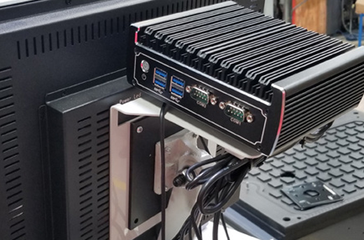
Attach the controller to its mount by sliding the standoffs through the key slots (see Figure 11).
-
Find the PathPilot Controller for 15L Lathe/PCNC Mills (PN 50848) provided. Then, remove the film from the double-sided tape on the case.
-
Put the case below the PathPilot Controller VESA Mount. Press down firmly to attach it in place.
-
Connect all USB accessories to the controller (or USB hub, if you’re using one):
-
Jog Shuttle (PN 30616)
-
Keyboard
-
Mouse
-
Monitor
-
Connect the monitor’s video cable to the PathPilot controller.
-
Route the loose end of the video cable toward the monitor, and then connect it to the monitor.
-
Connect the power supply to the PathPilot controller.
-
Route the loose end of the power cords (from the USB hub and both PathPilot controller units) to a power strip, and then connect them.
-
Connect the DB-25 interface cable into the DB-25 outlet on the side of the electrical cabinet.
-
Route the loose end of the DB-25 interface cable to the PathPilot Controller for 15L Lathe/ PCNC Mills case, and then connect it to the mill interface port.
-
Find the Ethernet cable and connect it to the Ethernet outlet on the PathPilot controller for 15L Lathe/PCNC Mills case.
-
Route the loose end of the Ethernet cable toward the PathPilot controller, and then connect it to the PathPilot controller.
-
Secure the wire loom, Ethernet cable, and power supply cables to the Controller Arm with six wire tie mounts and six cable ties.
Looking for more information?
This is a section of the 15L operator's manual. To view the whole manual, go to Tormach document UM10225.
If you have additional questions, we can help. Create a support ticket with Tormach Technical Support at tormach.com/how-to-submit-a-support-ticket for guidance on how to proceed.