Enclosure - PCNC 1100
Purpose:
This document details installation of the PCNC 1100 full enclosure. Prior to enclosure installation, first install the Control Relocation Kit (PN 33302).
PCNC 1100 Enclosure | Qty. | PN |
Enclosure Light Cover Window | 5 | 34435 |
Lamp 115 VAC | 5 | 34436 |
Enclosure Large Door Window | 4 | 34433 |
Enclosure Side Window | 2 | 34434 |
Control Relocation Kit | 1 | 33302 |
#7 Drill | 1 | 34507 |
#21 Drill | 1 | 34521 |
10-32 Tap | 1 | 34569 |
1/4-20 Tap | 1 | 34570 |
Tap Wrench | 1 | 36041 |
NOTE: If any of these items are missing, contact Tormach Customer Service for a replacement at (608) 849-8381.
Recommendations:
IMPORTANT! Install the following items on the machine first, before installing the enclosure:
Control Relocation Kit (required)
Power Drawbar (optional add-on)
Automatic Tool Changer (optional add-on)
IMPORTANT! The following are required for installation of the enclosure:
Power Drill/Screw Driver
Socket Set/Wrench
IMPORTANT! Due to minor stand inconsistencies, you may need to drill/tap extra holes to fasten some parts to the machine base.
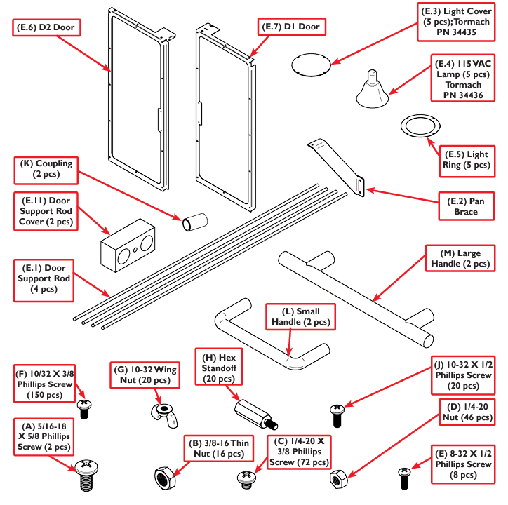
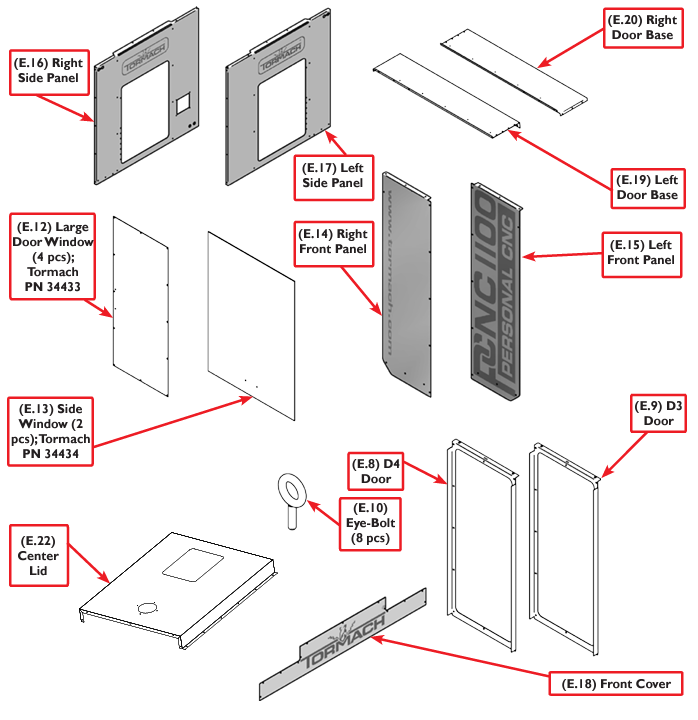
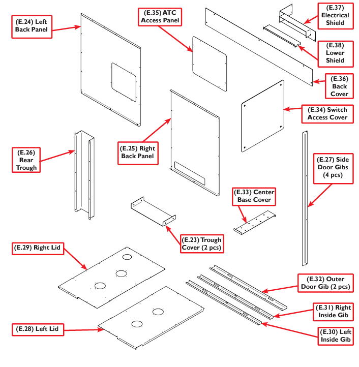
Enclosure Installation
In preparation for enclosure installation, remove the stainless steel cover strip along front of the machine stand (see Figure 1).
Remove the side/rear splash guards from both sides of chip pan (see Figure 1).
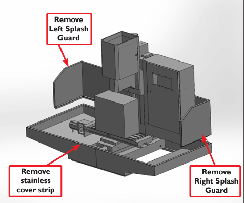
Figure 1
Place the Electrical Shield (E.37) around the right corner of the mill (see Figure 2).
Using six F screws, attach the Lower Shield (E38) to the bottom of the Electrical Shield (E.37) as shown in Figure 2.
NOTE: Back of the Electrical Shield tucks into the underside of the cabinet.
Next, mark, drill, and tap; use #21 Drill and 10-32 tap to make three holes on the side of the electrical cabinet where the existing holes are located in the Electrical Shield (E.37) as seen in Figure 2.
Once holes are drilled and tapped, secure Electrical Shield into place using three (F) screws as seen in Figure 2.
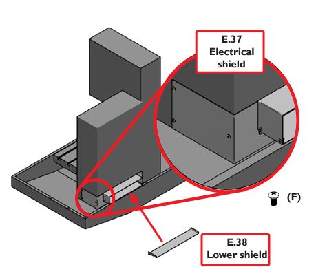
Figure 2
NOTE: Use butyl tape (included) to create a seal on the bed; test fit pieces prior to tape application (see Figure 3).
Place Right Rear Panel (E.25) on top of the right rear side of the machine stand (see Figure 3).
NOTE: Slotted holes rest against the machine base. Verify that the slotted holes line up with factory drilled and tapped holes.
Once you have the holes in place, loosely fasten this panel to the machine stand using 1/4-20 x 3/8” screws (C); use #7 Drill and 1/4-20 tap.
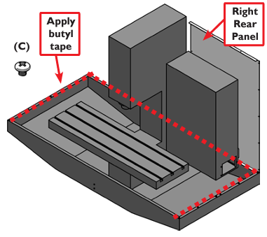
Figure 3
Place the Right Side Panel (E.16) on top of the right side of the machine stand (see Figure 4).
NOTE: Slotted holes rest against the machine base. Verify that the slotted holes line up to the factory drilled and tapped holes.
Once you have the holes in place loosely fasten this panel to the machine stand using 1/4-20 x 3/8” screws (C); use #7 Drill and 1/4-20 tap.
Once fastened to the base, loosely fasten the two panels together with (F) screws along the corner where the two panels meet.
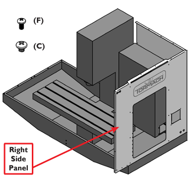
Figure 4
Place the Left Rear Panel (E.24) on top of the left rear side of the machine stand (see Figure 5).
NOTE: Slotted holes rest against the machine base. Verify that slotted holes line up to factory drilled and tapped holes.
Once you have the holes in place loosely fasten this panel to the machine stand using 1/4-20 x 3/8” screws(C); #7 Drill and 1/4-20 tap.
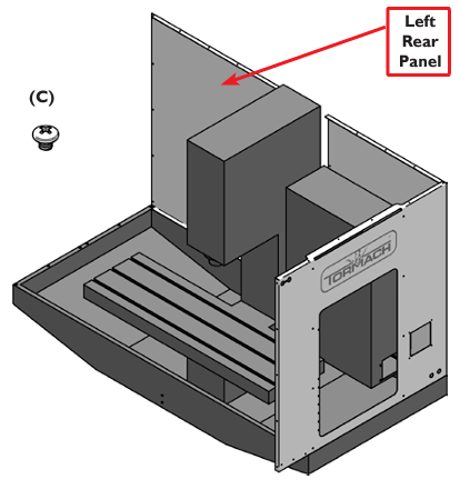
Figure 5
Place the Left Side Panel (E.17) on top of the left side of the machine stand (see Figure 6).
NOTE: Slotted holes rest against the machine base. Verify that slotted holes line up with factory drilled and tapped holes.
Once you have the holes in place loosely fasten this panel to the machine stand using 1/4-20 x 3/8” screws (C); #7 Drill and 1/4-20 tap.
Once fastened to the base, loosely fasten the two panels together with (F) screws along the corner where the two panels meet.
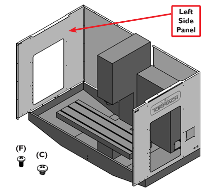
Figure 6
Hold the Door Support Rod Cover (E.11) on the outside of the Right Side Panel (E.16) as seen in Figure 7.
Using one (A) screw, fasten the rod cover in place from the inside of the panel.
Connect two Door Support Rods (E.1) together with one threaded Coupling (K) and tighten; repeat process for remaining rods and coupling.
Slide two assembled rods into holes in the Left Side Panel (E.17) and then shift them back into the Right Side Panel’s rod cover for support (see Figure 7).
Place the second rod cover over the rods now protruding on the outside of the Left Side Panel (E.17). Using one (A) screw, fasten the cover in place from the inside of the panel.
NOTE: In this step, installation of the covers and rods aid with lid assembly, but will be removed in a later step.
NOTE: Do not allow side panels to flex outward and allow rods to fall. Temporarily stretching a string taunt between the two side panels alleviates this problem (see Figure 7).
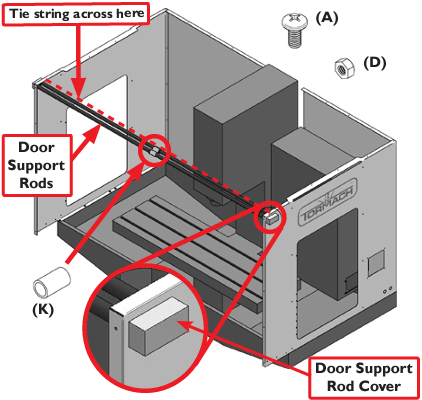
Figure 7
Place the upper Right Lid (E.29) on top of the right rear panel, right side panel and door support rods (see Figure 8). Loosely fasten with (F) screws along the rear and side panels.
Once all screws are in, tighten securely.
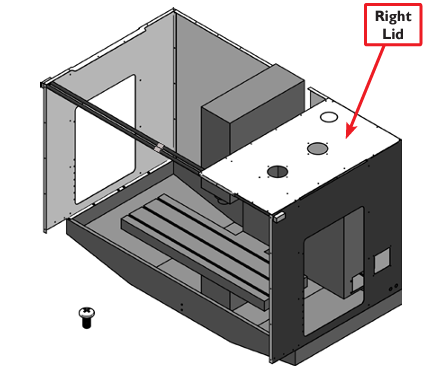
Figure 8
Place the upper Left Lid (E.28) on top of the left rear panel, left side panel, and door support rods (see Figure 9). Loosely fasten with (F) screws along the rear and side panels.
Once all screws are in, tighten securely.
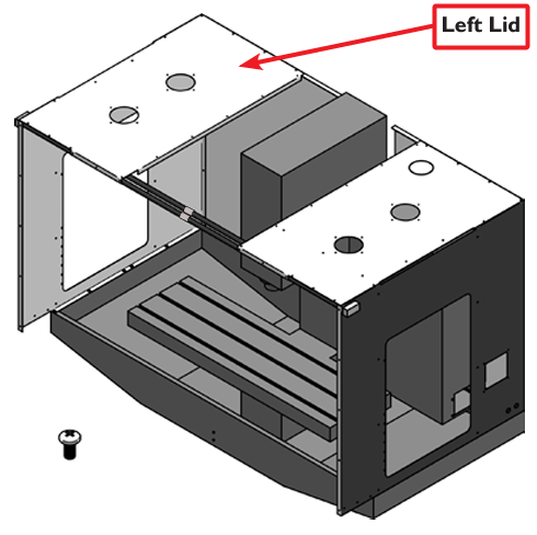
Figure 9
Place the Center Lid (E.22) on top of the left/right lids, and door support rods (see Figure 10). Loosely fasten with (F) screws along each side of the lid.
Once all screws are in, tighten securely.
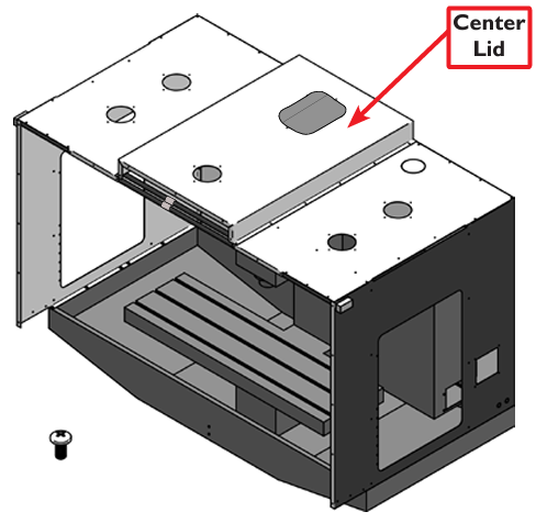
Figure 10
If string was used across the two side panels to prevent them from flexing outward, remove it at this stage (see Figure 7).
Place the Left Front Panel (E.15) onto the left front corner. Loosely fasten with (F) screws along the side and top edges of the front panel (see Figure 11).
Place the Right Front Panel (E.14) onto the right front corner (see Figure 11). Loosely fasten with (F) screws along the side and top edges of the front panel.
Once all screws are in, tighten securely.
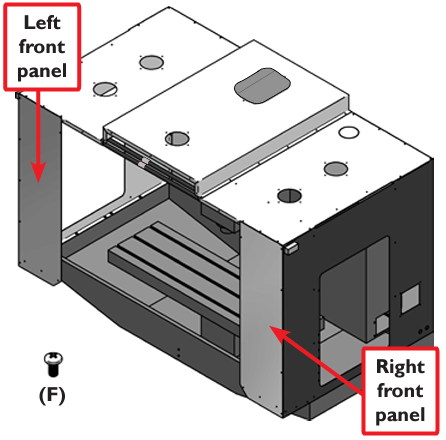
Figure 11
Place the Front Cover (E.18) onto the front of the enclosure assembly (see Figure 12). Loosely fasten with (F) screws along the side and top edges of the front panel.
NOTE: The Front Cover provides rigidity between the left and right sides. To ease alignment, lift on different areas of the enclosure.
Once all screws are in, tighten securely.
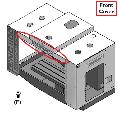
Figure 12
Place the center Back Cover (E.36) onto the back of the enclosure assembly (see Figure 13). Loosely fasten with (F) screws along the side and top edges of the front panel.
NOTE: The cover provides rigidity between the left and right sides. To ease alignment, lift on different areas of the enclosure.
Once all screws are in, tighten securely.
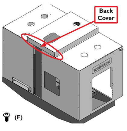
Figure 13
Place the Rear Trough (E.26) onto the center back see Figure 14). Loosely fasten with (F) screws along side of panel.
NOTE: The trough provides rigidity between the left and right sides. To ease alignment, lift on different areas of the enclosure.
Once all screws are in, tighten securely.
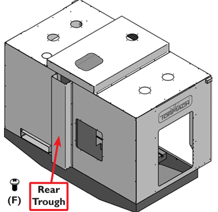
Figure 14
Place the two Trough Covers (E.23) onto the center back from the previous step (see Figure 15). Loosely fasten with (F) screws along the edges of the panels.
Place the ATC Access Panel (E.35) onto the left rear panel (see Figure 15) and loosely fasten with (F) screws along the edges of the panel.
Once all screws are in, tighten securely.
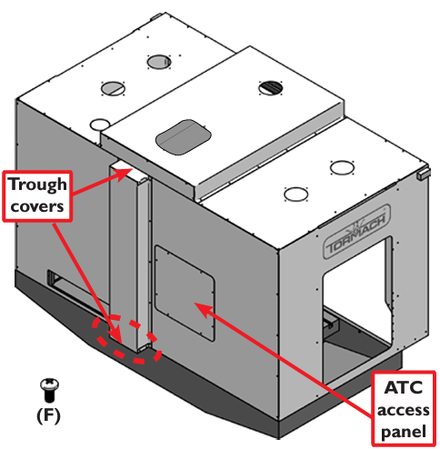
Figure 15
Place the Switch Access Cover (E.34) onto the right side panel (see Figure 16). Loosely fasten with (F) screws along the edges of the access panel.
Once all screws are in, tighten securely.
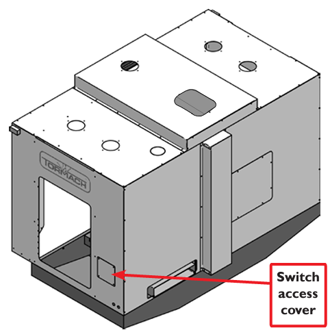
Figure 16
Place the Left Door Base (E.19) to where the large flange is inside of the chip pan (see Figure 17). Loosely fasten with (F) screws along the front left and left side panels.
On the inside flange you will find a series of 1/4” holes. These holes are provided so you can drill and tap the chip pan using a .201” diameter drill bit and a 1/4-20 tap.
Once the holes are drilled and tapped, fasten with (C) screws.
Once all screws are in, tighten securely.
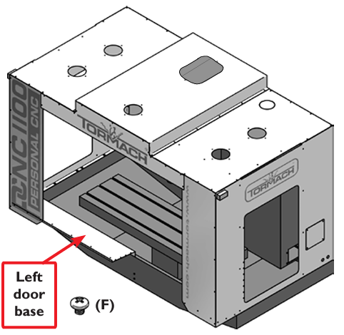
Figure 17
Place the Right Door Base (E.20) to where the large flange is inside of the chip pan (see Figure 18). Loosely fasten with (F) screws along the front left and left side panels. On the inside flange there is a series of 1/4” holes. These holes are provided so you can drill and tap the chip pan using a .201” diameter drill bit and a 1/4-20 tap.
Once the holes are drilled and tapped, fasten with (C) screws.
Once all screws are in, tighten securely.
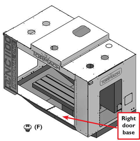
Figure 18
Place the Center Base Cover (E.33) over the left and right door bases (see Figure 19). Loosely fasten with (F) screws along the edges of the panel.
NOTE: Apply butyl tape under Center Base Cover (E.33).
NOTE: The Pan Brace (E.2) is located on the underside of the left door base.
Thread (F) screw through the Center Base Cover (E.33), through the left door base and into the flange of the Pan Brace at the screw location (see Figure 19). Once all screws are in and started, tighten securely.
The Pan Brace has two holes where the brace meets the chip pan (see Figure 19).These holes are provided so you can drill and tap the chip pan using a .159” diameter drill bit and a 10- 32 tap. Once the holes are drilled and tapped, fasten with (F) screws.
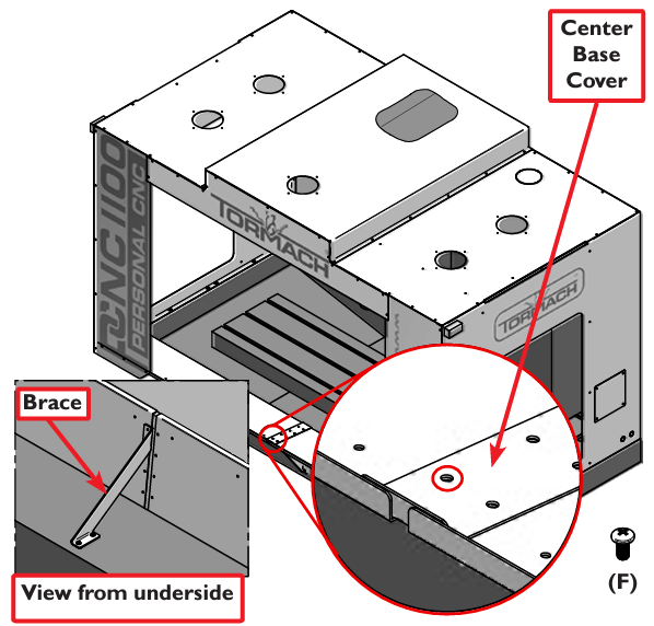
Figure 19
Stack the left inside door gib (E.30) onto the outside door gib (E.32), aligning the rectangular slots (see Figure 20). Loosely fasten with (F) screws along the center of the gibs.
NOTE: The screws go through both gibs and screw into the left door base.
Stack the right inside door gib (E.31) onto the second outside door gib (E.32), aligning the rectangular holes (see Figure 20). Loosely fasten with (F) screws along the center of gibs.
NOTE: The screws go through both gibs and screw into the right door base.
Once all screws are in, tighten securely.
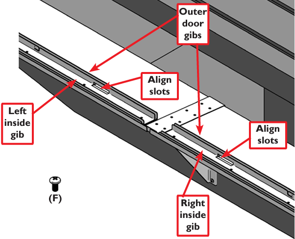
Figure 20
Place one Side Door Gib (E.27) on the inside of the Left Side Panel and fasten with screws (F) as seen in Figure 21.
Place one Side Glass window (E.13;Tormach PN 34434) into the side door gib (see Figure 21).
NOTE: The small handle holes in the Side Window are located at the bottom of the window when installed.
Hold the Side Window in place and fasten the other Side Door Gib (E.27) using (F) screws, trapping the side window and allowing vertical movement only (see Figure 21).
Fasten the Small Handle (L) into place using (E) screws as seen in Figure 21.
IMPORTANT! Do not overtighten. Side Window may crack.
Repeat the window install procedure for the Right Side Panel.
Place a 115 VAC Lamp (E.4; Tormach PN 34436) on top of the Center Lid as shown in Figure 22.
Place the Light Ring (E.5) over the light and fasten into place using (J) screws around perimeter of ring.
From inside of the enclosure, thread Hex Standoffs (H) onto protruding portion of exposed screws (see Figure 22).
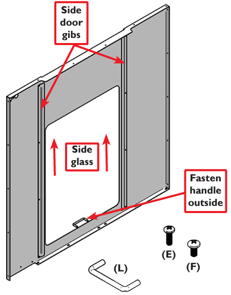
Figure 21
 CAUTION! Fire Hazard: Use only compact florescent light bulbs (not supplied) rated at 75 watts or less to reduce fire risk. Failure to do so could result in death, serious injury, and/or machine damage.
Align the Light Cover (E.3; Tormach PN 34435) onto the Hex Stand-offs (H) and secure with Wing Nuts (G).
IMPORTANT! Do not overtighten. Light Cover may crack or break.
Repeat lamp installation procedure for the remaining four 115 VAC Lamps.
NOTE: If ceiling height does not allow center lamp installation, attach the Light Cover only.
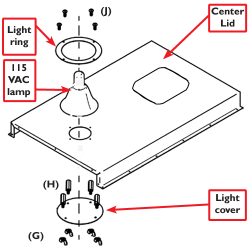
Figure 22
Place one Large Door Window (E.12; Tormach PN 34433) inside the D1 Door frame (E.7) and fasten with (C) screws and (D) nuts as seen in Figure 23.
IMPORTANT! Do not overtighten. Large Door Window may crack.
Attach one Large Handle (M) on the outside of the door using two (E) screws.
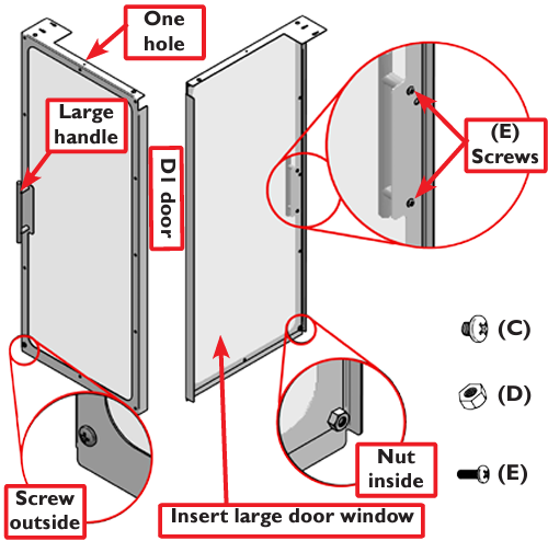
Figure 23
Place one Large Door Window (E.12; Tormach PN 34433) inside the D2 Door Frame (E.6) and fasten with (C) screws and (D) nuts as seen in Figure 24.
IMPORTANT! Do not overtighten. Large Door Window may crack.
Attach one Large Handle (M) on the outside of the door using two (E) screws.
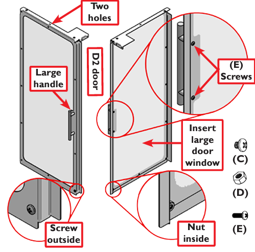
Figure 24
Place Large Door Window (E.12; Tormach PN 34433) inside the D3 Door Frame (E.9) and fasten with (C) screws and (D) nuts as seen in Figure 25.
IMPORTANT! Do not overtighten or Large Door Window may crack.
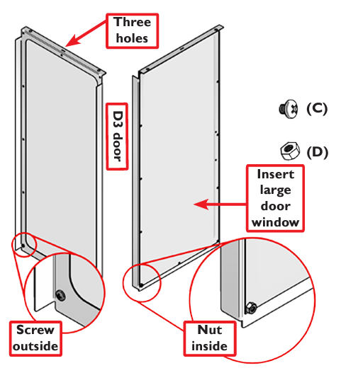
Figure 25
Place Large Door Window (E.12;Tormach PN 34433) inside the D4 Door Frame (E.8) and fasten with (C) screws and (D) nuts as seen in Figure 26.
IMPORTANT! Do not overtighten. Large Door Window may crack.
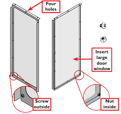
Figure 26
Place one (B) nut on each of eight Eye Bolts (E.10) as seen in Figure 27, and screw on as far as they will go onto each Eye Bolt.
Place each Eye Bolt into the hanging holes located on each door (see Figure 27). Once the Eye Bolts are through the door frame, thread another (B) nut onto the bottom side of each Eye Bolt; tighten securely.
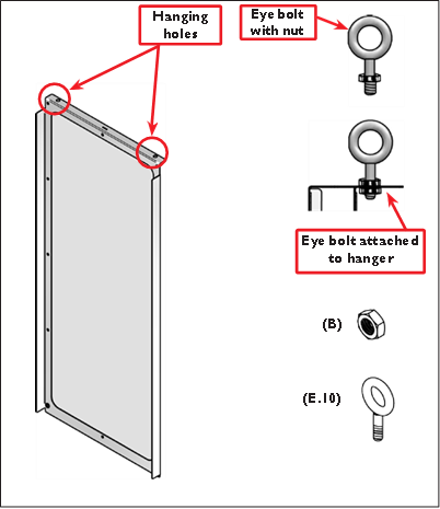
Figure 27
Remove the Door Support Rod Covers (E.11) from both of the two side panels (E.16 and E.17) as shown in Figure 28.
Slide the rear Door Support Rod out of the left side panel (E.17) enough to allow you to thread the Eye Bolts of Door 4 onto the rear rod.This door will be located on the left side of the coupling when looking at the machine from the front.
Slide the rear rod through panel E.17 (Left Side Panel) giving you enough space to thread the Eye Bolts of Door 3 onto the rear rod.This door will be located on the right side of the coupling when looking at the machine from the front.
Once doors are on rod, slide rear rod back into the holes of both side panels (E.16 and E.17).
NOTE: Make sure the rod does not come loose during next steps.
Slide Doors 3 and 4 to the outside of each side (open as far as possible).
Slide the front Door Support Rod out of the left side panel (E.17) enough to allow you to thread the Eye Bolts of Door 2 onto the front rod.This door will be located on the left side of the coupling when looking at the machine from the front
Next, slide the front rod through panel E.17 (Left Side Panel) allowing enough space to thread the eye bolts of Door 1 onto the front rod.This door will be located on the right side of the coupling when looking at the machine from the front.
Note: Front door flanges overlap rear doors.
Once doors are on the rod, slide front rod back into the holes of both side panels (E.16 and E.17).
Reattach the removed door support rod cover.
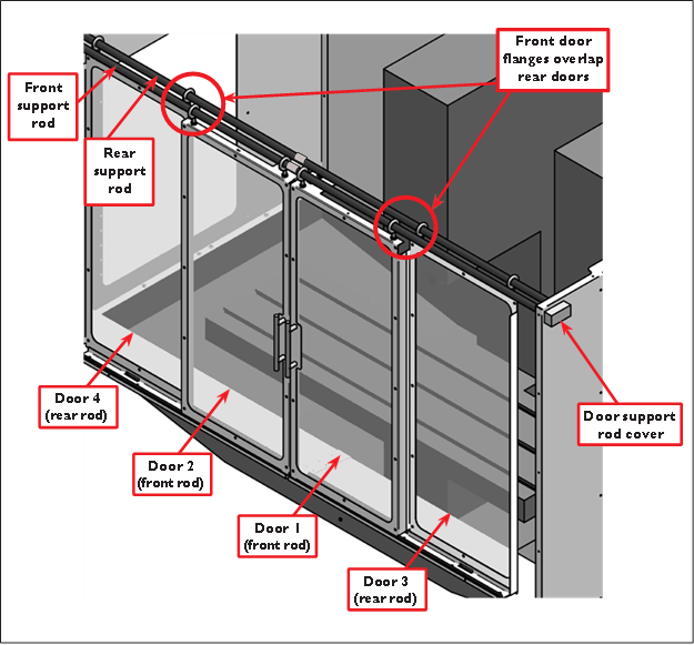
Figure 28
Adjust the height of Door 4 first by adjusting the eye bolt (B) nuts up and down until you have about 1/8” gap between the bottom of the door and the top of the door track (see Figure 29).When adjusting, make sure the door hangs level.
Repeat this procedure for the remaining doors in this order: Door 3, Door 2, Door 1.
Apply a small amount of general-purpose grease on each door support rod to allow doors to slide easier.
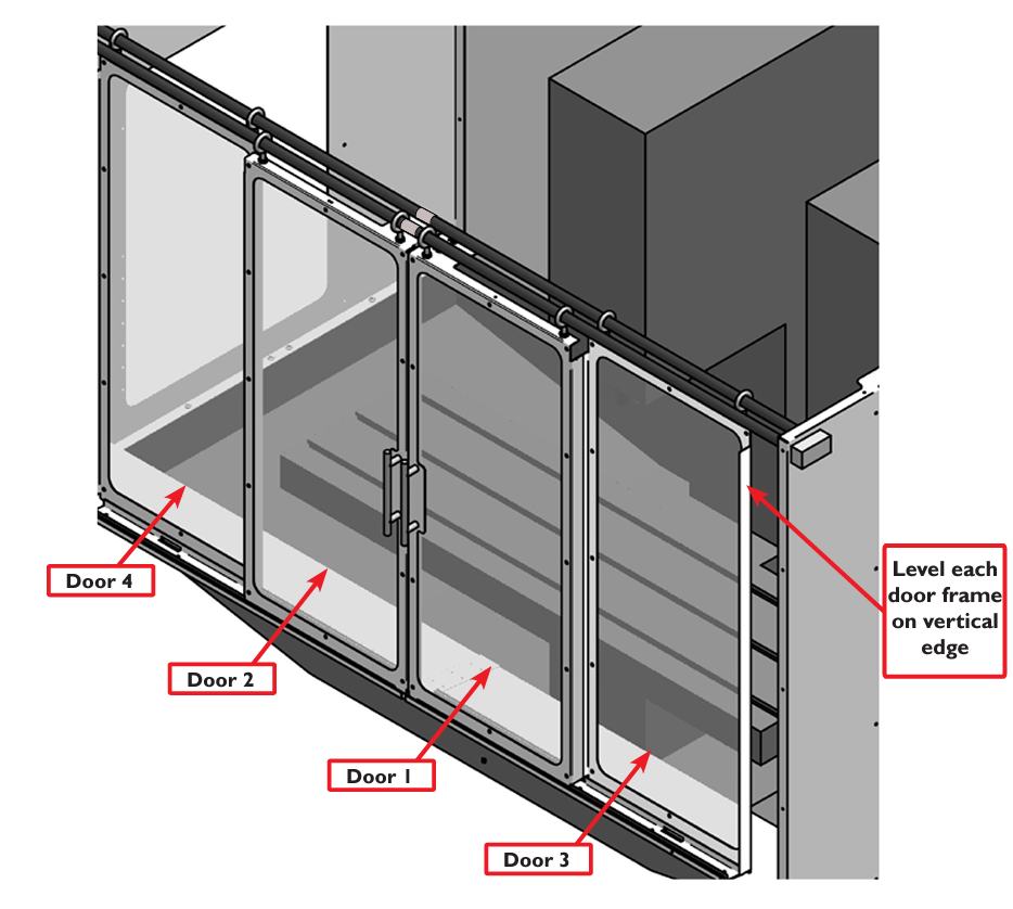
Figure 29
To view a PDF version of your manual, go to Tormach document TD10257.
If you have additional questions, we can help. Create a support ticket with Tormach Technical Support at tormach.com/how-to-submit-a-support-ticket for guidance on how to proceed.
