Install PathPilot Controller
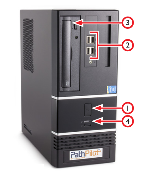
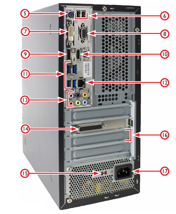
Review the connections on the front and rear of the PathPilot controller as shown in Figures 3.9 and 3.12. When all the connections are complete, place controller in the controller compartment located on the right side of the stand.

Figure 3.9

Figure 3.12
Item # | Connection or Component |
1 | Power/Reset with LED |
2 | USB Connectors (4) |
3 | Optical Drive |
4 | Hard Drive LED |
5 | PS/2 Connector |
6 | USB Connectors (2) |
7 | DVI Connector |
8 | VGA Connector |
9 | DP* |
10 | HDMI* |
11 | Blue USB Connectors (4) |
12 | Ethernet Connector |
13 | Audio Connections* |
14 | Mill Interface Port |
15 | Voltage Setting Switch |
16 | PCI Expansion Slot |
17 | AC Power Connector |
*NOTE: Do not use these controller features.
Set up and connect the PathPilot controller as follows:
Confirm Voltage Setting Switch (#15) is set to proper voltage for the geographic location before connecting power. Plug the power cord into the AC Power Connector (#17) on the PathPilot controller.
Connect ferrite end of DB-25 interface cable to Mill Interface Port (#14).
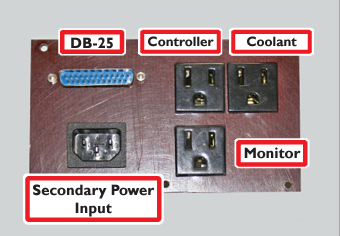
Plug controller, monitor, loose end of DB-25 interface cable (included), and secondary power cord (included with PCNC 1100 only) into Power Connection Panel (see Figure 3.11), located under the electrical cabinet.
Connect monitor to either the DVI Connector (#7) or the VGA Connector (#8).
Connect keyboard, optional jog shuttle, optional ATC, and optional USB I/O board to Blue USB Connectors (#11).
Connect other USB devices to any USB Connectors (#2, #6, or #11); do not use wireless keyboard/mouse.

Figure 3.11
Looking for more information?
This is a section of the PCNC 1100 operator's manual. To view the whole manual, go to Tormach document UM10349.
If you have additional questions, we can help. Create a support ticket with Tormach Technical Support at tormach.com/how-to-submit-a-support-ticket for guidance on how to proceed.
