PCNC 1100 Maintenance
Regular Maintenance
Scheduled maintenance intervals are detailed in the table below.
Mill Maintenance Schedule
Frequency | Completed | Item |
Daily | Check coolant level (PCNC 1100: 7-gallon capacity, PCNC 770: 5-gallon capacity) | |
Check oiler level and top off as needed (Auto Oiler capacity 2.1 quarts / Manual Oiler 0.25 quart) | ||
Retract and release manual oiler plunger each time mill is powered on and after every four hours of operation | ||
Clean chips from ways, carriage, and bellows’ covers | ||
Spray exposed, non-painted metal surfaces with WD-40® or similar to prevent rust |
Weekly | Check drawbar for wear; grease and adjust if needed | |
Clean chip basket on coolant tank | ||
Check air gauge/regulator for proper PSI (90 PSI minimum) | ||
Use mild cleaner to clean all exterior surfaces (no solvents) |
Monthly | Remove coolant tank pump. Clean out sediment buildup in tank; reinstall | |
Inspect electrical cabinet vent(s) for dust build up; if necessary wipe vents with clean cloth. If dust accumulation is excessive, use compressed air to remove | ||
Pull back way covers and inspect ways and ball screw for proper lubrication (on all axes) |
Every Six Months | Inspect spindle belt for nicks, fraying, or other noticeable signs of wear | |
Inspect way covers as needed to ensure proper operation; replace as needed | ||
Inspect oil system for blockages; clean/replace as needed | ||
Check lubrication hoses for signs of wear or cracking; replace as needed | ||
Check X-axis flex conduit for signs of wear or cracking; replace as needed |
Every 12 Months | Check limit switches for proper function; replace as needed | |
Check door switches for proper function; replace as needed |
Rust Prevention
Exposed iron and steel surfaces will rust if proper care is not taken to protect them. The following recommendations will slow or reduce the onset of surface rust.
If possible, install the PCNC mill in a temperature- and humidity-controlled environment.
Always use a flood coolant recommended for machining; never use water or a coolant that does not contain rust inhibitors. When using a water-based coolant, always mix the coolant concentrate to the dilution ratio recommended by the coolant manufacturer.
If the mill is not used for more than 72 hours, apply a light mist of water repellent oil such as WD-40 to the exposed bare metal surfaces.
Trapped areas are susceptible to rust. Apply way oil or machine oil directly to the table surface under the trapped area when you mount a vise or fixture on the mill.
NOTE: Light surface rust on the table can be removed with a machinist’s stone.
Way Covers
Way covers serve an important function – they keep chips and abrasive debris from damaging the slideways. Clean and inspect the way covers per maintenance schedule.
Flood Coolant System
Regular maintenance of the flood coolant system will prolong the service life of the coolant pump.
Collect tramp oil with an absorbent pillow or a mechanical oil skimmer. Replace pillows as needed.
PN | Description |
31925 | Floating Tramp Oil Collection Pillow |
35244 | Oil Skimmer Kit |
Coolant can scum if allowed to sit for a prolonged period. Replace coolant as needed.
Check the impeller for obstructions.
Clean coolant reservoir regularly.
NOTE: Check with local authorities on proper handling and disposal of new and used coolant.
Lubrication System
The lubrication system distributes oil to 15 points throughout the mill. This includes the 12 sliding surfaces (four each on the three axes) and three ball screw nuts – some of the most critical and expensive mechanical parts of the mill. Any dirt or foreign material suspended in the oil is going to be delivered directly to these parts and can dramatically shorten the operational service of the mill.
Use only new, high quality ISO VG 68 grade Machine Oil.
PN | Description |
31386 | Tormach WL-68 |
Alternative choices include Perkins Perlube WL-68, Tonna 68 (Shell), Vactra No. 2 (Mobil), Way-lube 68 (Sunoco), WayLube 68 (Texaco), Febis 68 (Esso) or equivalent oil.
Be sure to clean off the cover and surrounding area to remove debris before refilling the oil reservoir. The strainer at the top of the reservoir is not a filter.
Periodically inspect way surfaces and ball screws to confirm a proper oil film is present. Absence of an oil film can be an indicator of clog oil lines or fittings.
The X, Y, and Z slideways have a thin layer of PTFE-filled acetyl plastic bonded to each sliding surface.
The material is commonly known under the trade names of Turcite® or Rulon®.
This is state of the art technology for oil lubricated slideways and superior to plain ground surfaces or hardened and chromed surfaces. No data is available on how long the material will last on the PCNC, but there have been no reports of appreciable wear, even on mills that are reported to have seen more than 5000 hours of operation. If you use the lubrication system and keep the protective bellows in good shape, the slideways are not normally maintenance items.
A shot of lubrication should be given after every four hours of operation and after the mill has stood unused for 48 hours or longer.
If the mill’s lubrication system becomes clogged, brass oil system fittings can be cleaned by soaking them overnight in a degreaser or solvent like WD-40. Replace clogged plastic oil line tubing.
Manual Pump Specifics
The manual pump is spring loaded. Retract and release the plunger and the spring force creates light hydraulic pressure to push oil through the lines. You can get the oil out quicker by pushing the plunger a bit, but too much force can pop off oil lines. A shot of lubrication should be given after every four hours of operation and each time the mill is powered on.
You will have a more uniform distribution of oil if the mill is moving when the hydraulic pressure is applied.
The manual pump draws oil from the reservoir on the pull stroke and delivers it to the mill on the push stroke. If at some point the oil pump seems much easier on the push stroke then make certain that you do not have a broken oil line.
Extreme axis positions can expose the oil distribution channels that are cut into the way support saddle surfaces. If the pump is used in those positions, the hydraulic force of the oil will not apply it throughout the mill as intended. Instead, the oil will simply squirt out at the point where the oil channel is exposed.
After a long period of inactivity (or in cold conditions), the oil system may become clogged. For more information, refer to Tormach service bulletin Flushing the Lubrication System.
Drawbar and TTS Collet
The drawbar, drawbar thrust washer and TTS collet are wear items and should be replaced regularly. Proper lubrication and maintenance of the drawbar and TTS collet will maximize tool holding force and prolong the service life of these components.
Clean tool holder shanks as needed with a degreaser
Keep the inside of the collet clean and dry. Collets must be cleaned of preservative shipping oil when first received
Lubricate outside of collet and inside of spindle taper with Anti-seize Grease (PN 31273). Use sparingly to avoid risk of the lubricant migrating to the inside of the collet. Only the first inch of the spindle taper needs to be lubricated; remove excess lubricant with a degreaser
PN | Description |
31273 | Anti-seize Grease |
Lubricate the threaded section of the drawbar, the thrust shoulder of the drawbar, and the thrust washer with Anti-seize Grease (PN 31273)
Do not overtighten the drawbar. The recommended drawbar torque is 30 ft-lbs. Exceeding 40 ft-lbs of torque will reduce the operational service of the collet and drawbar
Visually inspect the drawbar, thrust washer, and collet for signs of wear such as damaged or galled threads and replace as needed. It is recommended that the drawbar, thrust washer, and collet be replaced as a set
Spindle Belt
Inspect the spindle belt as indicated in the maintenance schedule. Replace if necessary.
PN | Description |
30389 | PCNC 1100 Replacement Spindle Belt |
31435 | PCNC 770 Replacement Spindle Belt |
Advanced Maintenance
Overview
Each PCNC is tuned at the factory to meet or exceed certain precision metrics. These metrics are indicated on the Certificate of Inspection that is included with each mill, along with the actual values measured for each metric as part of Tormach’s Quality Assurance program. The following advanced maintenance procedures may become necessary over the ownership lifetime to maintain the original factory precision:
Gib adjustment
Angular contact bearing preload adjustment
Geometry adjustment (tram)
These adjustments are generally used to address component wear-in over time, but may also be needed to correct misalignment resulting from misuse, a hard crash of the system, or when some components are removed or replaced due to damage. The frequency of these procedures depends on both how the mill is used and how often.
The adjustments in this section should not be considered lightly as a wrong adjustment can adversely affect mill precision. Before making any of the adjustments in this section ask:
Why am I making this adjustment?
How will I measure the effect of this adjustment?
What unintended consequences may result from this adjustment?
If you do decide to make an adjustment, do not assume where the error is from. The error could be attributed to a specific problem, or from the combined effect of several problems. Mistakenly making the wrong adjustment can make matters worse. As a practical example, if the Z-axis gib is too loose, it will cause the spindle head to tilt slightly downwards, toward the column. It would be fairly easy to incorrectly assume that the issue is with the column and base connection (often referred to as tram), and make an adjustment by inserting shims between the column and base. Instead of correcting the real issue, this adjustment causes the column to slant back to correct for the head leaning down. Now, the mill is running in a slight parallelogram in addition to a loose head.
For instructions on how to measure lost motion, see: Lost Motion Testing - PCNC 1100
For instructions on how to adjust your gibs and/or ACB’s, see: Mill Gib/AC Bearing Adjustment and Backlash Compensation - PCNC 1100
Geometry Adjustment of Precision Mating Surfaces
All precision mating surfaces are pinned together with tapered dowels during assembly at the factory. The pinned connection ensures that factory alignment is maintained in the event of a tool crash. Each dowel pin has a small metric threaded hole in the center that can be used to extract the dowel should it be required for disassembly.
Under typical usage, no adjustment of pinned connections should be necessary. In the event of a hard crash, shims can be used to make minor alignment adjustments between pinned components. Small adjustments (less than .010”) will generally not require a full disassembly of the pinned connection. In these cases, the alignment dowels can be left in place, and the shims can be inserted into a small opening created by loosening the bolted connections.
Spindle Bearing Adjustment
PCNC 1100 only
When correctly adjusted for preload, sustained high spindle speed will bring the spindle bearings to about 155°F (68°C). This is a normal condition. Higher preload in the spindle bearings will result in even higher temperatures and excessive wear.
NOTE: For information on rebuilding PCNC 1100 spindle cartridges, refer to: PCNC 1100 Spindle Rebuild
PCNC 770 only
During operation, sustained high spindle speed will bring the spindle bearings to about 155°F (68°C). This is a normal condition. Spindle bearing preload is set at the factory and is not operator-adjustable
IMPORTANT! Do not attempt to adjust spindle bearing preload on PCNC 770 spindles. Failure to do so will adversely impact spindle balance.
Spindle Calibration
To improve spindle speed accuracy, calibrate the speed control signal. This procedure is not necessary for mill operation.
This procedure requires access to the electrical cabinet while the mill is powered on.
CAUTION! Electric Shock Risk: Points within the electrical cabinet contain high voltage. Do not make contact with any part of electrical cabinet unless specifically instructed to do so. Failure to do so could result in serious injury.
In the PathPilot interface, toggle the spindle belt position by clicking Spindle Range until the LED light is illuminated next to LO.
IMPORTANT! Ensure the spindle belt is in the low position. A mismatch between the spindle range button in PathPilot and the actual spindle belt position will result in the commanded speed being different from the indicated RPMs.
Set the spindle speed to 500 RPM. Depending on your workflow, do one of the following:
Type S500 in the MDI line and press Enter on the keyboard
Type 500 into the S DRO and press Enter on the keyboard.
WARNING! Moving Parts Hazard: Keep hands, feet, hair, and clothing away from moving parts. Failure to do so could result in serious injury or death.
Ensure there are no tools in the spindle; start the spindle.
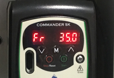
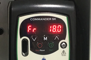
Inspect the value displayed on the front panel of the VFD; the recommended range is detailed in the following table:
PCNC 1100 | 34-36 Hz (see Figure 10) |
PCNC 770 | 17.5-18.5 Hz (see Figure 11) |

Figure 10

Figure 11
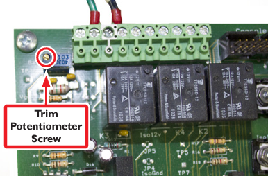
If the value is outside of the recommended range, use a small, flat-bladed screwdriver to adjust the Trim Potentiometer Screw on the Machine Control Board (see Figure 12) until the value on the front panel of the VFD displays within range.

Figure 12
NOTE: If better accuracy is needed, use a tachometer to measure actual spindle speed.
Mill Transportation
Follow these steps when preparing mill for transport to a new location:
Place a solid block of wood on the table underneath the spindle and lower the Z-axis so that the wood is slightly compressed.
All bare metal surfaces should be oiled before moving the mill to protect against corrosion.
If required, the Y-axis motor can be removed by loosening the motor coupling and removing the four motor mounting screws. Likewise, the Z-axis motor can also be removed to reduce the overall height of the mill.
IMPORTANT! Take care to secure motors after removal from mill so wiring is not damaged during transport.
Remove the PCNC mill from the stand and secure to a shipping pallet for vehicle transport.
IMPORTANT! PCNC mill must be removed from the Tormach stand (if equipped) for transport. The stand is not designed to support the weight of the mill during transport.
PCNC 1100 only
Warranty is void if the mill is disassembled. Tormach recognizes that there are situations where operators need to disassemble their mill and has made provisions in the design of the mill to facilitate this. Nevertheless, Tormach cannot be held responsible for alignment, precision and operating functions after the mill has been disassembled. Test your mill before disassembling it.
The major sub-assemblies of spindle head, column and base are bolted and dowelled together so the mill can be separated into smaller components to meet very challenging transport problems. Note, however, that this entails disconnecting wiring and the lubrication lines. We recommend taking photographs from all angles, including detailed photos of any wires or oil lines that will be taken apart. Dowel pins must be removed before the bolts on disassembly. Dowel pins must be installed before the bolts on re-assembly.
Tormach strongly recommends that all precision sliding and rotating joints remain intact during disassembly. This means that you should not remove ball screws, bearings, or separate sliding joints. For example, in reference to the Upper Mill Assembly (exploded view), located in chapter 11, Diagrams and Parts Lists, you should not separate item 82 (Z-axis saddle) from item 75 (machine column). Instead you should separate item 19 (head casting) from item 82 (Z-axis saddle).
Any additional, more detailed advice should be sought from Tormach Technical Support.
PCNC 770 only
For information on mill disassembly, refer to documentation that ships with Moving Kit (PN 31333).
This is a section of the PCNC 1100 operator's manual. To view the whole manual, go to Tormach document UM10349.
If you have additional questions, we can help. Create a support ticket with Tormach Technical Support at tormach.com/how-to-submit-a-support-ticket for guidance on how to proceed.
