Flood Coolant Kit - PCNC 440
Purpose
This document gives instructions on installing the flood coolant kit on a PCNC 440.
Product Information
Product: PCNC 440 Flood Coolant Kit (PN 35719)
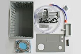
Quantity | Description |
1 | |
1 | 3/4 in. ID Clear Tubing (PN 37115) |
8 | 10-32 Nut (PN 34101) |
8 | 10-32 × 1/2 in. Screw (PN 34100) |
1 | |
1 | Chip Screen (PN 37112) |
1 | |
1 | Coolant Hose Adapter (PN 35989) |
1 | Coolant Tank (PN 35711) |
1 | Coolant Tank Cover (PN 35710) |
1 | Funnel Tray (PN 37113) |
2 | Hose Clamp (PN 37116) |
4 | Rubber Washer (PN 37114) |
NOTE: If any items are missing, we can help. Create a support ticket with Tormach Technical Support at tormach.com/how-to-submit-a-support-ticket for guidance on how to proceed.
Required Tools
This procedure requires the following tools. Collect them before you begin.
Adjustable wrench
Center punch
Clean rag
Electric drill
Isopropyl alcohol
Marker
Phillips screwdriver
Silicone sealant
Thread seal tape
Set Up the Flood Coolant Kit
Put the coolant tank cover on top of the coolant tank.
Use four 10-32 ×1/2 in. screws and 10-32 nuts to mount the coolant pump to the coolant tank cover.
Put one end of the 3/4 in. ID clear tubing into the coolant tank cover. You can use a hose clamp on one end of the 3/4 in. ID clear tubing to prevent it from pulling out of the coolant tank.
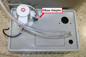
Figure 1: Coolant tank assembly.
Wrap the threads of the coolant hose adapter with thread seal tape. Then, put it into the mounting bracket on the machine column.
Tighten the fixing screw to secure the adapter in its position.
Connect the 1/4 in. coolant hose to the coolant hose adapter.
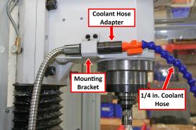
Figure 2: Coolant hose assembly.
Put one provided silicone washer into each end of the chrome-armored hose.
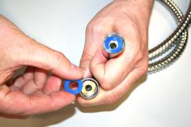
Figure 3: Silicone washers on the chrome-armored hose.
Route the chrome-armored hose around the rear of the machine, and then connect it to the open end of the coolant hose adapter.
Wrap the threads of the elbow adapter on the coolant pump with thread seal tape.
Connect the loose end of the chrome-armored hose to the elbow adapter on the coolant pump.
Remove the access panel from the chip pan.
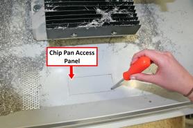
Figure 4: Access panel on the chip pan.
Put the provided chip screen in place of the chip pan's access panel.
Put one hose clamp on the loose end of the 3/4 in. ID clear tubing, and then attach it to the funnel tray.
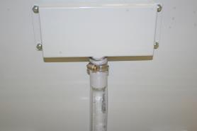
Figure 5: 3/4 in. ID clear tubing attached to the funnel tray.
Use the funnel tray as a template: put it below the access panel on the chip pan, and then use a marker to mark its four holes.
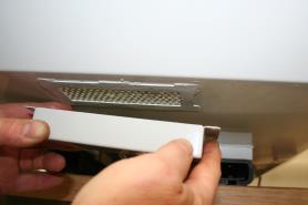
Figure 6: The funnel tray below the access panel.
Use a center punch (or similar) to mark the four locations that you marked in Step 14. Then, use a 7/32 in. drill bit to drill the holes.
Use four 10-32 × 1/2 in. screws, rubber washers, and 10-32 nuts to attach the funnel tray to the chip pan.
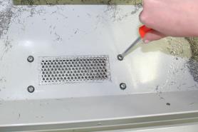
Figure 7: Funnel tray attached to the chip pan.
Use isopropyl alcohol and a rag to clean the perimeter of the funnel tray.
Apply a thin strip of silicone sealant around the perimeter of the funnel tray to seal against leaks.
Route the power cord on the coolant pump to the machine's power strip, and connect it to the power strip.
To view a PDF version of your manual, go to Tormach document TD10405.
If you have additional questions, we can help. Create a support ticket with Tormach Technical Support at tormach.com/how-to-submit-a-support-ticket for guidance on how to proceed.
