Install the Monitor and the PathPilot Controller
Install the Controller Arm
Tools and Items Required
4 mm hex wrench
6 mm hex wrench
8 mm hex wrench
17 mm hex wrench
17 mm socket wrench
21 mm wrench
Dead-blow hammer (or similar)
Phillips screwdriver
Pry bar
CAUTION! Sharp Objects Hazard: Before opening the shipping crate, you must put on work gloves and safety eyewear that meets ANSI Z87+. If you don't, the shipping crate and steel straps could cut you, causing serious injury.
Put on work gloves and eye protection.
Open the Controller Arm crate with a pry bar.
Secure the square tube arm to the machine stand with two M8 socket head cap screws, two M8 flat washers, two M8 lock washers, and a 6 mm hex wrench. Verify that the white nylon washer is located toward the bottom of the mounting pad.
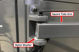
Figure 1: White nylon washer on the square tube arm.
Put the monitor post into the square tube arm. Verify that the monitor bracket is toward the top, and that the threaded holes face the holes in the square tube arm.
Tighten the cross bolt on the square tube arm with a 17 mm socket wrench and a 17 mm hex wrench.
With a 21 mm wrench, remove the monitor bracket from the Controller Arm, and rotate it so that the largest mounting plate is facing up.
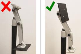
Figure 2: Incorrect and correct orientations of the monitor bracket on the Controller Arm.
NOTE: The largest mounting plate is for the monitor, and the smallest mounting plate is for the keyboard tray.
Tighten the three pivot bolts on the monitor bracket with an 8 mm hex wrench and a 16 mm wrench.
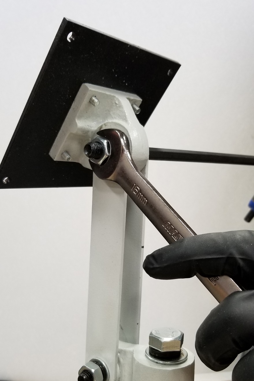
Figure 3: Tightening the monitor bracket in place.
Tip! This makes it easier to install the monitor, which you'll do later in this installation procedure.
Tap the end plug into the square tube arm with a dead-blow hammer (or similar).
Secure the keyboard table to the monitor bracket with four M5 socket head cap screws, four M5 flat washers, four M5 split lock washers, and a 4 mm hex wrench.
Attach four wire tie mounts to the monitor post with four 4 mm flat head machine screws and a Phillips screwdriver.
Install the Monitor
The PathPilot controller mount allows you to install the PathPilot controller behind the monitor (which is attached to the Controller Arm).
NOTE: If you're using a Touch Screen Kit (PN 35575), you must first remove the stock mounting bracket from the back of the monitor.
Put the PathPilot Controller VESA Mount (PN 50382) against the monitor mounting plate. Then, put the monitor on the other side of the PathPilot controller mount, and align the holes on the three components.
Attach the monitor, PathPilot Controller VESA Mount, and monitor mounting plate together with four M4 × 12 mm socket head cap screws (provided with the PathPilot Controller VESA Mount).
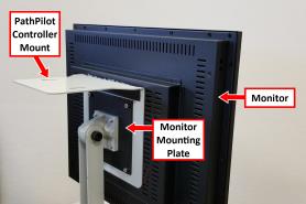
Figure 4: PathPilot controller mount attached to the back of the monitor.
Adjust the position of the monitor and the keyboard tray with an 8 mm hex wrench and a 16 mm wrench. Once complete, securely tighten the pivot screws.
Install the PathPilot Controller
The PathPilot controller attaches to the top of the PathPilot controller mount and behind the monitor.
Put four standoffs into the controller and tighten them by hand.
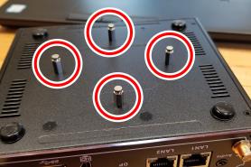
Figure 5: Installing the standoffs on the controller.
Find the four M4 screws and the VESA plate included with the controller. Then, mount the VESA plate to the PathPilot Controller VESA Mount (PN 50382). Make sure to put it flat side down with the keyholes toward the monitor.
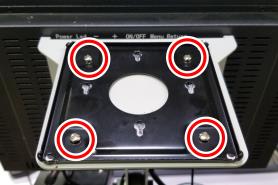
Figure 6: VESA plate mounted onto the PathPilot Controller VESA Mount (PN 50382).
Attach the controller to its mount by sliding the standoffs through the key slots.

Figure 7: Controller attached to the top of the mount.
Find the Machine Interface Adapter provided. Then, remove the film from the double-sided tape on its case.
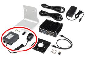
Figure 8: Adapter identification.
Put the case below the PathPilot Controller VESA Mount. Verify that the case is oriented so that the DB-25 port is facing to the left side of the monitor from behind. Press up firmly to attach it in place.
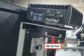
Figure 9: Adapter attached to the bottom of the mount.
NOTE: You may have to mount the case at an angle to fit between any screws on the PathPilot Controller VESA Mount.
Connect all USB accessories to the controller:
Jog Shuttle (PN 30616) (Optional)
Keyboard
Mouse
Monitor
Connect the monitor's video cable to the controller.
Route the loose end of the video cable toward the monitor, and then connect it to the monitor.
Connect the power supply to the controller.
Route the loose end of the power cords from both PathPilot controller units to a power strip, and then connect them.
Find the DB-25 interface cable provided with this kit. Connect the DB-25 interface cable into the DB-25 outlet on the side of the electrical cabinet.
Route the loose end of the DB-25 interface cable to the Machine Interface Adapter, and then connect it to the DB-25 port.
Find the Ethernet cable, and then connect it to the Ethernet outlet on the Machine Interface Adapter.
Route the loose end of the Ethernet cable toward the controller and then connect it.
Secure the wire loom, Ethernet cable, and power supply cables to the Controller Arm with six wire tie mounts and six cable ties.
Looking for more information?
This is a section of the PCNC 440 operator's manual. To view the whole manual, go to Tormach document UM10372.
If you have additional questions, we can help. Create a support ticket with Tormach Technical Support at tormach.com/how-to-submit-a-support-ticket for guidance on how to proceed.