Probe & ETS Setup
Background
Calibrating your Passive Probe and Electronic Tool Setter (ETS) is an important procedure to get the most accurate measurements when establishing either a Work or Tool Offset. Prior to starting, be sure you are on the latest version of PathPilot.
Tools
1-2-3 Block
Ring Guage
Passive Probe
Electronic Tool Setter
Metric Allen Keys
Electronic Tool Setter (ETS)
There are three steps to set up the ETS. Complete the following steps in the order listed:
https://youtu.be/pba5QXhbVS8?si=SNXuaJ4fqDnXbt9GReference the Spindle Nose
NOTE: You must repeat this procedure after each time that you reference the Z-axis.
Identify a home location for your ETS. You can use anywhere within the machine's area of travel as the home location, so long as you can center the spindle above the ETS.
Remove the tool holder from the spindle.
From the PathPilot interface, in the Tool DRO field, type 0. Then select the Enter key.
Jog the spindle until it's over the ETS. Then, slowly jog the Z-axis down (-Z) toward the contact pad on the ETS.
From the PathPilot interface, on the ETS Setup tab, find the ETS G37 Spindle Nose Reference section, and select ETS Spindle Ref.
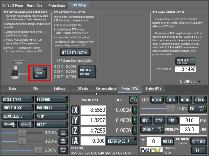
The Z-axis moves down (-Z) until the spindle nose contacts and triggers the ETS.
The spindle nose is now referenced to the ETS.
Set the G37 Position
Remove the tool holder from the spindle.
From the PathPilot interface, in the Tool DRO field, type 0. Then select the Enter key.
Jog the spindle until it's over the ETS, and center the spindle over its contact pad.
Jog the Z-axis up (+Z) until it's at a safe clearance height for your longest tool.
NOTICE! If the Z-axis is set below the highest position, there's a risk of tool collision.
From the PathPilot interface, on the ETS Setup tab, find the ETS G37 Position Setup group, and select Set G37 ETS Position.
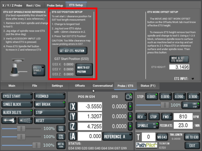
The G37 position is now set.
Verify that the X, Y, and Z ETS position displayed in their DRO fields are accurate.
NOTE: The values displayed in these DRO fields are in G53.
Set the ETS Height
Before you begin to use the ETS, you must first use the PathPilot interface to set its work offset.
To set the ETS height:
Set a new Z zero position for the currently selected work offset.
Put the ETS on the known reference height (from Step 1).
Jog the spindle until it's over the ETS.
From the PathPilot interface, on the Probe tab, select the ETS Setup tab. Then find the ETS Work Offset Setup group, and select Move & Set ETS Height.
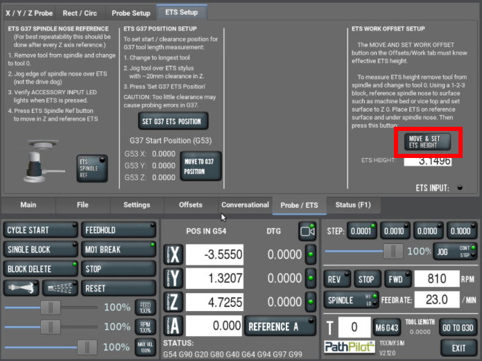
The Z-axis moves down (-Z) until the spindle nose contacts and triggers the ETS.
In the ETS Height DRO field, verify that the length of the ETS updated.
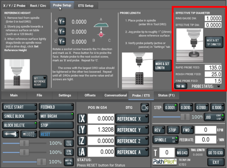
Probe Setup
There are three steps to set up the ETS. Complete the following steps in the order listed:
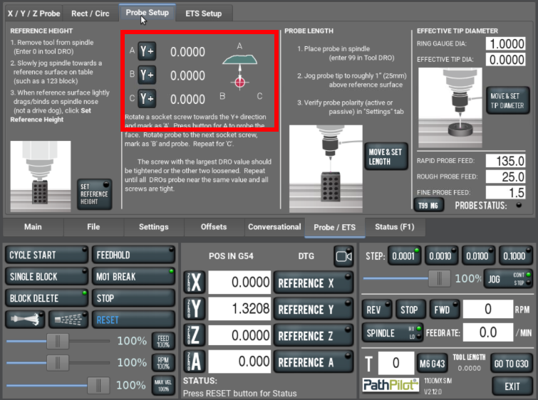
Probe Tip Concentricity
Load your Probe into the spindle and plug it into ACC Port 1.
Verify that tool number 99 is active in the Tool DRO.
Verify probe polarity (active or passive) in the Settings tab, then come back to the Probe Setup tab.
Press the probe tip and make sure that, from the PathPilot interface, on the Probe tab, the Probe Status light comes on.
Rotate using the socket head screws as reference towards the Y+ Direction and mark as 'A'. Press the button for A to Probe the face.
Rotate the probe to the next screw, mark as 'B'. Press the button for B to Probe the face.
Repeat for 'C'
The screw with the largest DRO Value should be tightened or the other two loosened.
Repeat steps 5 trough 8 until all DRO’s probe near the same value and all screws are tight.
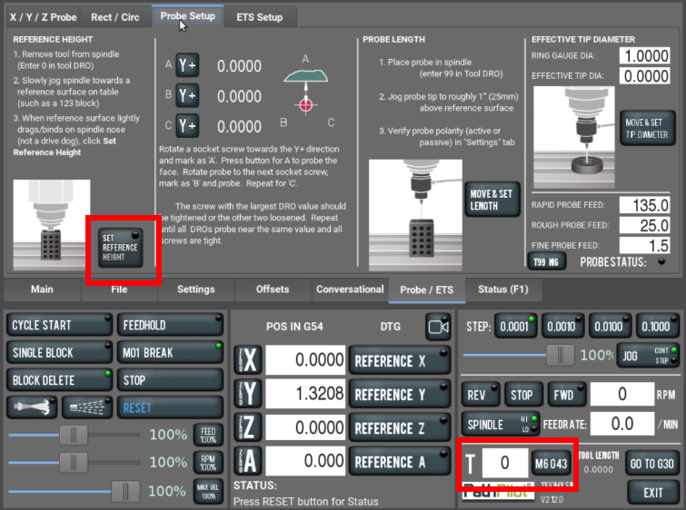
Set the Spindle Nose Reference Height
Remove any tool from Spindle, and make Tool 0 active.
Slowly jog the spindle towards a reference surface on table such as a 1-2-3 Block.
When reference surface lightly drags/binds on spindle nose(not a drive dog on MX machines), click SET REFERENCE HEIGHT.
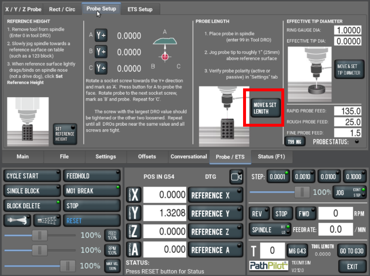
Set the Probe Length
Load your Probe into the spindle and plug it into ACC Port 1.
Verify that tool number 99 is active in the Tool DRO.
Verify probe polarity (active or passive) in the Settings tab, then come back to the Probe Setup tab.
Press the probe tip and make sure that, from the PathPilot interface, on the Probe tab, the Probe Status light comes on.
Jog the probe tip to roughly ~25mm from the reference surface used when setting the Reference Height.
Click the Move and Set Length button and wait for the routine to finish.
Set Effective Tip Diameter
Load your Probe into the spindle and plug it into ACC Port 1.
Verify that tool number 99 is active in the Tool DRO.
Verify probe polarity (active or passive) in the Settings tab, then come back to the Probe Setup tab.
Press the probe tip and make sure that, from the PathPilot interface, on the Probe tab, the Probe Status light comes on.
Enter your ring gauge diameter value into the Ring Gauge DIA DRO.
Using a micrometer or calipers, measure your probe tip diameter, and enter the measured value into the Effective Tip DIA DRO.
Jog the probe until the tip is roughly centered in the ring gauge (make sure that the height will allow it to make proper contact with the ID of the ring gauge).
Press the Move & Set Tip Diameter Button, and wait for the routine to finish
The Effective Tip DIA will update after the routine completes.