Unpack the Machine Crate and Mount the Machine
If you have purchased a Machine Stand, see that install here.
CAUTION! Sharp Objects Hazard: Before opening the shipping crate, you must put on work gloves and safety eyewear that meets ANSI Z87+. If you don't, the shipping crate and steel straps could cut you, causing serious injury.
Put on work gloves and eye protection.
Cut and remove the steel straps on the shipping crate with snips.
Disassemble the shipping crate with a hammer and pry bar. Start with removing the top, followed by the four sides.
Remove and discard the plastic wrap from the machine.
Inspect the item(s):
Photograph any damage that may have occurred during shipping.
Verify the received goods against the packing list.
If there is any damage or shortages, you must contact Tormach within 30 days of receipt. Create a support ticket with Tormach Technical Support at tormach.com/how-to-submit-a-support-ticket for guidance on how to proceed.Cut and remove the shipping straps securing the tool box to the pallet.
The tool box contains the following items:
Drawbar
Drawbar thrust washer
Electrical cabinet key
Hex wrench set: 3 mm, 4 mm, 5 mm, 6 mm, 8 mm, and 10 mm
Phillips screwdriver
Tormach Tooling System (TTS) collet
Cut and remove the shipping straps securing the X-axis motor cover plate and X-axis limit switch cover plate from the pallet.
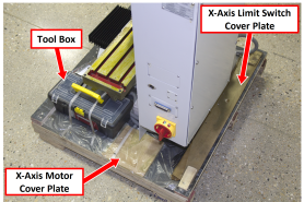
Figure 1: Components on the pallet.
Cut the shipping straps securing the operator box to the pallet.
Remove all packing materials from the spindle head.
Lift and Move the Machine
Move the machine's pallet and stand as close as possible to the desired location with a pallet jack. The machine stand must be positioned behind the machine.
Put the chip pan on top of the machine stand.
Remove any excess shipping grease on the machine with a mild degreaser (like WD40® or similar).
Remove the nuts from the four studs that hold the machine to the pallet with a 16 mm wrench. Discard the nuts.
WARNING! Transportation and Lift Hazard: Before moving the machine, you must confirm that all persons are clear of the area below the machine. Qualified professionals must transport, lift, and move the machine. Moving parts can entangle, pinch, or cut you, causing death or serious injury.
Secure an engine hoist to the eye bolt on the top of the machine column, and then lift the machine from above.
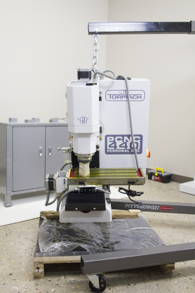
Figure 2: Engine hoist secured to the eye
WARNING! Crush Hazard: While lowering the machine onto the machine stand, you must keep your hands away from all moving parts. Moving parts can entangle, pinch, or cut you, causing death or serious injury.
Slowly and steadily lower the machine on to the chip pan. Confirm that the holes in the chip pan, machine, and machine stand are aligned.
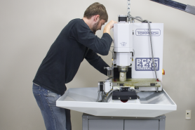
Figure 3: Lowering the machine onto the stand.
Secure the machine to the machine stand with a 10 mm hex wrench and four M12 × 100 mm socket head cap screws, four M12 washers, and four M12 nuts.
Once the machine is completely supported by the machine stand, remove the engine hoist.
Install the Emergency Stop Box
Identify the emergency stop mounting bracket (PN 53003) and two M6 flanged button head cap screws (PN 38206) included with the chip pan.
Install the emergency stop mounting bracket onto the right side of the chip pan with a 4 mm hex wrench.
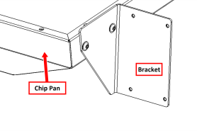
Figure 4: Emergency stop mounting bracket installed on the chip pan.
Identify the four M4 button head cap screws (PN 53009) included with the chip tray and emergency stop box connected to the machine's electrical cabinet.
Remove and set aside the four screws securing the lid of the emergency stop box with a Phillips screwdriver. Remove and set aside the lid.
NOTE: There are wires attached to the lid. Be careful not to pull on them.
Insert one M4 screw into each corner of the emergency stop box so that the threads of the screw stick out from the back of the box.
Attach the emergency stop box to the emergency stop mounting bracket with a 2.5 mm hex wrench.
Re-install the emergency stop box lid with the screws that you set aside earlier.
Install Cover Plates
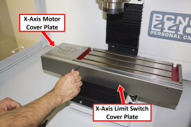
Find the X-axis motor cover plate and the X-axis limit switch cover plate that you set aside.
Attach the X-axis motor cover plate to the X-axis motor mount with two screws.
Attach the X-axis limit switch cover plate to the front of the machine table with two screws.
Looking for more information?
This is a section of the PCNC 440 operator's manual. To view the whole manual, go to Tormach document UM10372.
If you have additional questions, we can help. Create a support ticket with Tormach Technical Support at tormach.com/how-to-submit-a-support-ticket for guidance on how to proceed.
