v2.x ATC Control Board Kit for PCNC 440 Mills
Purpose
This document gives instructions on installing the v2.x ATC Control Board Kit for PCNC 440 Mills.
Product Information
Product: v2.x ATC Control Board Kit for PCNC 440 Mills (PN 51066)
Quantity | Description |
1 | ATC Control Board v2.x (PN 51023) |
NOTE: If any items are missing, we can help. Create a support ticket with Tormach Technical Support at tormach.com/how-to-submit-a-support-ticket for guidance on how to proceed.
Before You Begin
Update PathPilot. If you haven't yet done so, update to the latest version of PathPilot. You can either:
Download and install the update file from your controller by selecting the Update button on the Status tab.
Download the update file to a USB drive from the PathPilot support center and transfer it to your controller.
Disassembly
The ATC Control Board v2.x (PN 51023) replaces the following products:
ATC Control Board v1.4 (PN 35901)
Ribbon Cable (PN 38663)
Stepper Driver (PN 32793)
NOTE: The replacement ATC control board (v2.x) has an on-board stepper driver, so you'll no longer need PN 32793.
To remove the old control board:
Power off the machine and the PathPilot controller.
Push in the machine's red Emergency Stop button, which removes power to motion control.
From the PathPilot interface, select Exit.
Turn the Main Disconnect switch to OFF on the side of the electrical cabinet.
Remove the power plug(s) from the wall outlet. If your system is hardwired, isolate the machine by opening its circuit breaker(s).
Open the rear panel of your ATC.
Disconnect the air source from your mill and bleed pressure by pressing the button on any of the solenoids inside the ATC.
Remove the check valve and tubing from the solenoid block inside the ATC to make extra room. Use a marker or tape to identify the direction that the check valve is facing. To remove the tubing from the push to connect fittings, press on the black collar and pull the tubing out.
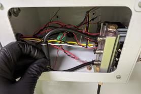
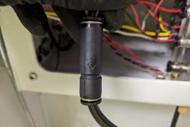
Disconnect the 6-pin green connector from the stepper driver and tuck it to the side. Disconnect the flat ribbon cable from the stepper driver and the control board. Remove the ribbon cable from the ATC and set it aside.
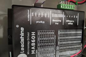
Remove the mounting nuts from the stepper driver with a 7 mm wrench and set it to one side. The new control board has an integrated stepper driver so you will not need this one.
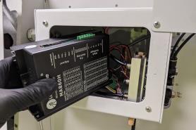
Remove the two larger power wires from green stepper driver connector. Disconnect them from the control board and set aside. These will not be needed for the new control board.
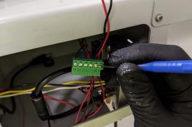
Transfer the Wires
You now have access to the ATC control board. In this section, you'll transfer most of the wires to new connectors before removing the control board.
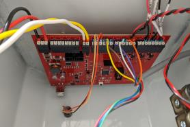
Find the 5-pin connector provided in this kit (connector J10).
Holding the connector in the orientation shown, transfer wires 201 (red), 200 (black), 818 (yellow) and 819 (white) from the old control board to the new connector as shown in the following image.
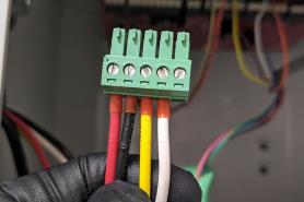
Find the 4-pin connector provided in this kit (connector J7).
Transfer wires 813 (red or blue) and 812 (black) to the new connector, as shown in the following image. If you have a foot pedal installed on your mill, transfer wires 829 and 830 from the PEDL connector on your control board (not shown).
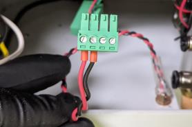
Full wire order for the 4-pin J7 connector (left to right): 813, 812, 829, 830.
Find the 8-pin connector provided in this kit (connector J1).
Transfer wires 805 (red), 804 (black), 807 (red), 806 (black), 809 (red), 808 (black) to the new connector as shown in the following image (starting on the left).
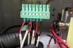
At this point, the remaining wires on the ATC control board (from left to right) are the tray-in sensor, the carousel index sensor, and the drawbar release button (as shown in the following image).
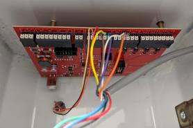
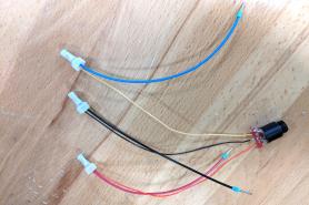
Some early production units may have short wires on the tray-in sensor. If you have the older style of sensor shown here without enough slack to pull the wires outside of the ATC enclosure you will need the extension wires supplied with your upgrade kit. (if your wires are longer and match the newer red, blue, black color scheme, go to Step 9.)
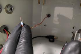
“Old style” sensor wires (extension required)
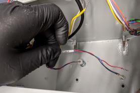
“New style” sensor wires (OK as is)
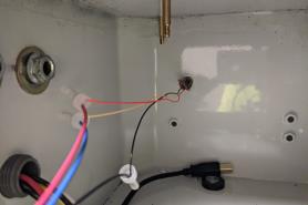
The tray-in sensor unscrews from the case of the ATC. Remove it for easy access to the wires. Crimp extensions onto the tray-in sensor wires. After installing the extensions, replace it in the ATC.
If using the extensions, match black to black, red to red, and yellow to blue.
Install the New Control Board
NOTICE! You must take care to keep the control board clean. Before you install the new control board, make sure that the ATC enclosure is free of chips or debris. The presence of chips could cause damage to the control board.
Remove the old control board from the ATC.
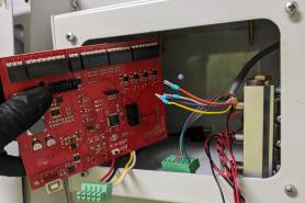
If you removed the tray-in sensor to add extensions, re-install it now.
Slide the terminal block assembly into the ATC and secure it using the studs that were previously used for the stepper driver.
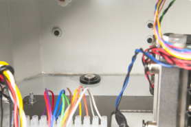
Install the new control board onto the mounting posts.
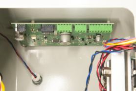
Plug in the USB control cable.
Plug in the two black molex connectors on the control board.
Plug in the 4-, 5-, and 8-pin green connectors.
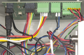
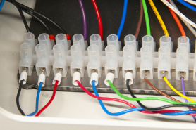
Connect wires 815 (orange), 814 (white), 822 (purple), 821 (yellow), 820 (brown) to the new terminal block provided in this kit.
NOTE: The wires that you're installing go from right to left, and they don't match the colors of the wires on the other side of the terminal block.
Don't mix up the order of the purple, yellow, and brown wires. If they're out of order, the tray indexing sensor won't function.
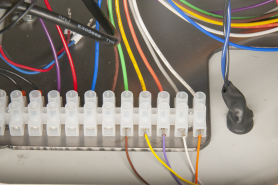
Remove the four stepper motor wires from the green connector you unplugged from the stepper driver. You can discard this connector — the wires will be connected to the new terminal block.
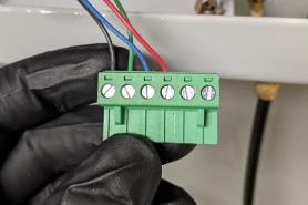
Place the four stepper motor wires into the new terminal block. The order, from right to left, is as follows: 800 (black), 801 (green), 802 (blue), 803 (red).
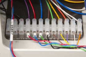
Connect the three wires from the tray in sensor to the last three terminal blocks. The order, from right to left, is: 826 (red), 825 (blue), 824 (black).
Reinstall the check valve you removed earlier (make sure to verify the orientation, as indicated previously by a marker or tape) and reconnect your machine to the air supply.
Power on the machine and the PathPilot controller.
Insert the power plug(s) into the wall outlet. If your system is hardwired, restore power to the circuit breaker(s).
Turn the PathPilot controller strip to ON.
Turn the Main Disconnect switch to ON on the side of the electrical cabinet.
Twist out the machine's red Emergency Stop button, which enables movement to the machine axes and the spindle.
Press the Start button.
Bring the machine out of reset and reference it.
Verify the alignment of the ATC tool tray. If required, use the ++ and -- buttons on the ATC tab to realign the tool tray. For information, see the documentation for the ATC.
NOTE: The tool tray position is stored as a setting on the control board. However, the settings from your original control board aren't transferred to new (replacement) control boards. This means that you may need to realign the tool tray after installing this kit.
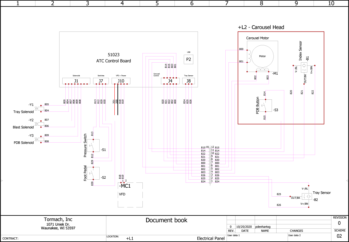
To view a PDF version of your manual, go to Tormach document TD10796.
If you have additional questions, we can help. Create a support ticket with Tormach Technical Support at tormach.com/how-to-submit-a-support-ticket for guidance on how to proceed.
