6 and 8 in. 4th Axis for PCNC 770/1100
Purpose
This document details the installation, setup, use, and maintenance of the following 4th Axis rotary tables with PCNC 1100 or PCNC 770 mills.
IMPORTANT! If you’re installing a 6 in. or 8 in. rotary table on an M or MX mill, refer to TD10552. If you’re installing a microARC 4, refer to TD10749.
Product Identification
Model | With 4th Axis Kit | Without 4th |
|---|---|---|
6 in. Motorized Rotary Table | PN 30290 | PN 30267 |
6 in. Super Spacer Rotary Table | PN 34123 | PN 33089 |
6 in. Tilting Rotary Table | PN 31996 | PN 31847 |
8 in. Motorized Rotary Table | PN 30289 | PN 30194 |
8 in. Super Spacer Rotary Table | PN 34122 | PN 33264 |
8 in. Tilting Rotary Table | PN 31997 | PN 31848 |
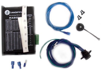
NOTE: For more information on axis drives, refer to Tormach technical document TD10173.
Overview
Performance Expectations
Rotary tables offer quick and accurate indexing or consistent rotary feed, and can be a cost effective way to turn a 3-axis mill into a 4-axis mill. They can be used for a wide variety of machining operations including drilling bolt patterns, milling angled slots, or making simple gears. Operating speed is 4 RPM, and the recommended backlash setting is 60-arc seconds. Avoid direct exposure to coolant.
Description | 8” Standard or Tilting | 6” Standard or Tilting | 8” Super Spacer | 6” Super Spacer |
Diameter of table | 200 mm (7.9”) | 160 mm (6.3”) | 200 mm (7.9”) | 160 mm (6.3”) |
Pilot Diameter | 1.18” | .985” | — | — |
Through Bore | MT-3 .850” (morse taper) | MT-2 .650” (morse taper) | 2.470” | 1.550” |
Width of T-slot | 12 mm (0.47”) | 10 mm (0.39”) | .425” | .465” |
Adjacent angle of T-slot | 90° | 90° | 60° | 60° |
Width of locating key | 15.875 mm (5/8”) | 15.875 mm (5/8”) | 15.875 mm (5/8”) | 15.875 mm (5/8”) |
Worm ratio | 1:90 | 1:90 | 1:90 | 1:90 |
Graduation of table | 360° (1° per graduation) | 360° (1° per graduation) | 360° (1° per graduation) | 360° (1° per graduation) |
Rotating angle per full axis motor step | 0.02° (1.2’) subdivide with microstepping | 0.02° (1.2’) subdivide with microstepping | 0.02° (1.2’) subdivide with microstepping | 0.02° (1.2’) subdivide with microstepping |
Motor steps | 200 steps/rev | 200 steps/rev | 200 steps/rev | 200 steps/rev |
Motor winding | 2 phase, 4 wire | 2 phase, 4 wire | 2 phase, 4 wire | 2 phase, 4 wire |
Motor induction | 3.5 mH | 5.73 mH | 3.5 mH | 3.5 mH |
Motor resistance | 0.42 Ω | 1.34 Ω | 0.42 Ω | 0.42 Ω |
Motor phase current | 5.5 A | 2.8 A | 5.5 A | 5.5 A |
Motor holding torque | 4.6 Nm (640 oz-inch) | 1.9 Nm (264 oz-inch) | 4.6 Nm (640 oz-inch) | 4.6 Nm (640 oz-inch) |
Motor mount | NEMA 34 | NEMA 23 | NEMA 34 | NEMA 34 |
Motor shaft | 1/2” | 1/4” | 1/2” | 1/2” |
Cable | 10 ft - 18 AWG shielded, twisted pair (Belden 1063a) | 10 ft - 18 AWG shielded, twisted pair (Belden 1063a) | 10 ft - 18 AWG shielded, twisted pair (Belden 1063a) | 10 ft - 18 AWG shielded, twisted pair (Belden 1063a) |
Product weight | Standard Table: 94 lbs (43 kg)1 Tilting Table:148 lbs (67 kg)2 | Standard Table: 76 lbs (31 kg)1 Tilting Table: 97 lbs (44 kg)2 | 141 lbs (64 kg)2 | 110 lbs (50 kg)2 |
1Can be shipped UPS 2Requires truck freight | ||||
Before You Begin
It’s important to note that, after you’ve installed the rotary table and 4th axis driver, you must complete the following procedures before initial use:
Fill the rotary table with oil. For information, see the Lubrication section later in this document.
IMPORTANT! Operating without lubrication voids warranty.
Adjust the backlash. For information, see the Adjusting Backlash section later in this document.
Uncrating and Inspection
Upon receipt, inspect all parts for damage and, if necessary, report issues to Tormach immediately. https://tormach.atlassian.net/servicedesk/customer/portals
Check to ensure all loose parts are removed from shipping container before discarding.
Installation
NOTE: Most photos shown in this document are of the PCNC 1100, but are applicable to the PCNC 770 as well.
Mounting Vertically (typical A-axis)
Position the 4th Axis on the left side of table (see Figure 1).
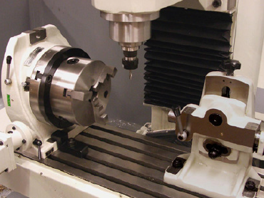
Figure 1
Use Toe Clamps to secure.
NOTE: The Tilting and Super Spacer tables are typically positioned on the right-hand side of table.
Mounting Horizontally (typical C-axis)
Position the 4th Axis on the right side of the table (see Figure 2).
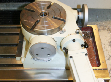
Figure 2
Use Toe Clamps (included) to secure.
Fitting Drive Module
Power off mill according to Power Off/On Procedure.
![]() WARNING! Electrical Shock Hazard: Be sure to power off machine before making any electrical modifications. Failure to do so could result in death and/or serious injury.
WARNING! Electrical Shock Hazard: Be sure to power off machine before making any electrical modifications. Failure to do so could result in death and/or serious injury.
Power Off/On Procedure | ||
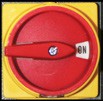
Power Off |
| 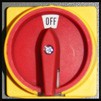 |
| ||
| ||
Power On |
|  |
| ||
| ||
| ||
Identify location D in electrical cabinet as shown in Figure 3 to install 4th axis drive.
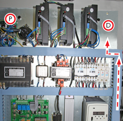
Figure 3
Loosely attach one M4 screw in the bottom of the two tapped holes; rest drive on screw.
Attach one M4 screw in the remaining tapped hole; tighten both M4 screws securely.
Mounting Interface Connector
Locate the blanking plate (if equipped) below the main disconnect switch, to the right of the electrical cabinet. Remove and set aside four screws.
NOTE: Use larger of two blanking plates for 4th Axis.
Thread the Interface Connector wires through the side of the electrical cabinet (see Figure 4 and inset); secure using four screws set aside in Step 1.
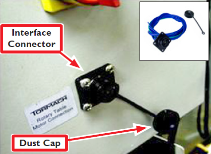
Figure 4
NOTE: Interface Connector’s Dust Cap is attached on bottom right screw (see Figure 4 and inset).
Ground Wire Connections
Remove wire trough covers in electrical cabinet; set aside.
Route wires 320-323 from Interface Connector through wire troughs and to location D as shown in Figure 3.
Older mills are equipped with a Ground Bar (see Figure 5), while newer mills have a green Ground Terminal Block (see Figure 6). Identify the ground connection specific to your mill and route green ground wire.
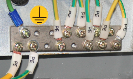
Figure 5: Ground Bar
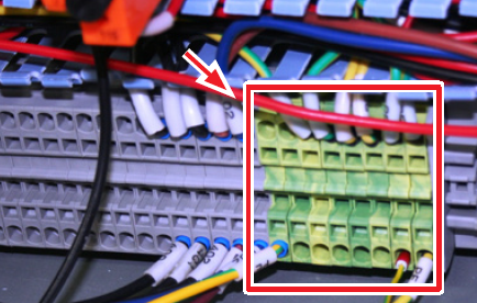
Figure 6: Ground Terminal Block
Based on ground connection identified in Step 3, either use pre-mounted ferrule for Ground Terminal Block connection (see Figure 6) or clip off Ferrule, strip wire back 1/4” and crimp on ring connector for Ground Bar connection (see Figure 5).
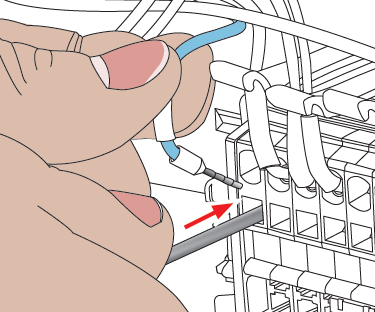
Figure 7
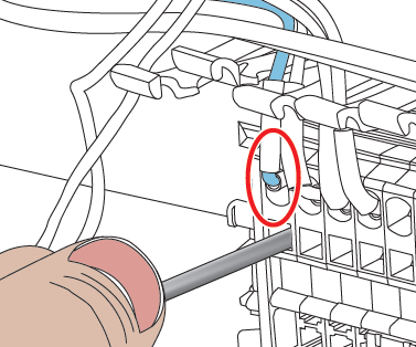
Figure 8
Make ground wire connection as detailed below:
Ground Bar |
|
|---|---|
Terminal Block |
|
Power Wire Connections
Identify the blue power wire (included) with two 1/4” crimp connector ends; cut it in half to make two power wires that are required for installation.
Using a wire stripper, strip off 1/4” of insulation on cut end of blue power wire to expose bare metal.
Add wire labels (included) to stripped ends of blue power wire. For more information, refer to PCNC 1100 Wiring Overview and PCNC 770 Wiring Overview sections later in this document.
NOTE: Wire connections for PCNC 1100 and PCNC 770 varies. See related section for information.
PCNC 1100
PCNC Mill | Serial Number |
1100 Series I | 1-1325 |
1100 Series II | 1326-1999 |
1100 Series 3 | 2000 and up |
Plug crimp connector end of wire 325 to connector marked –A on the DC Bus Board (at location P in Figure 3); plug crimp connector end of wire 324 to the connector marked +A (see Figure 9 and Figure 10). Refer to PCNC 1100 Wiring Overview section later in this document for wire labeling details.
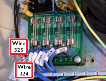
Figure 9: PCNC 1100 Series 1 & Series 2
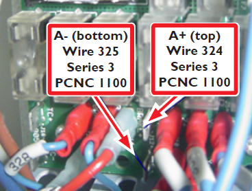
Figure 10: PCNC 1100 Series 3
IMPORTANT! Wire identification is critical; for more information, refer to PCNC 1100 Power Wiring Overview section later in this document.
Route loose end of power wire to drive (location D in Figure 3).
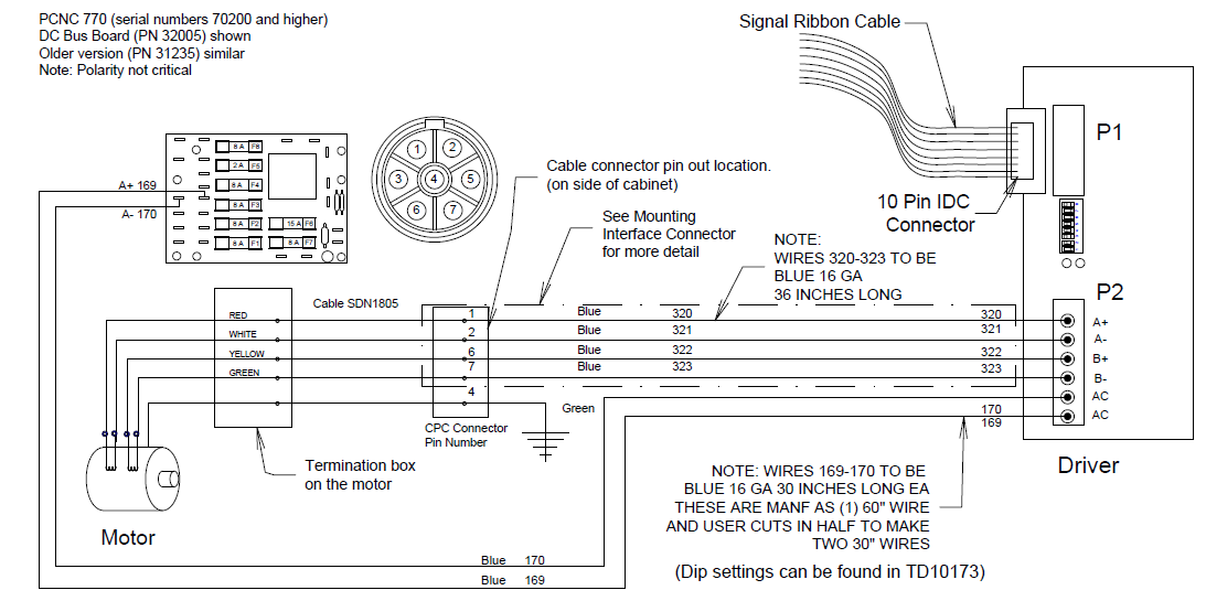
PCNC 770
PCNC Mill | Serial Number |
770 (early models) | 70000-70199 |
770 Series 3 | 70200 and up |
Plug crimp connector end of wire 170 to connector marked –A on the DC Bus Board (at location P in Figure 3); plug crimp connector end of wire 169 to the connector marked +A (see Figure 11 and Figure 12). Refer to PCNC 770 Wiring Overview section later in this document for wire labeling details.
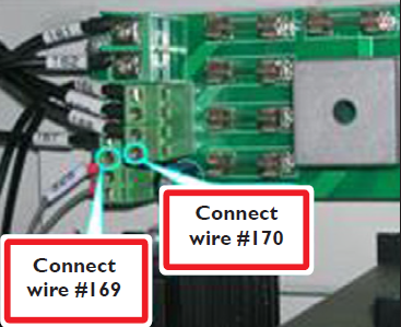
Figure 11: PCNC 770 Series 1 (early models)
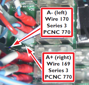
Figure 12: PCNC 770 Series 3
IMPORTANT! Wire identification is critical; for more information, refer to PCNC 770 Power Wiring Overview section later in this document.
Route loose end of power wire to drive (at location D in Figure 3).
PCNC 1100 Wiring Overview
PCNC 770 Wiring Overview
Drive Connections
In the electrical cabinet, locate the loose Ribbon Cable under the wire trough cover (in line with ribbon cables to existing drives).
Plug Ribbon Cable into IDC Connector on drive (see Figure 13).
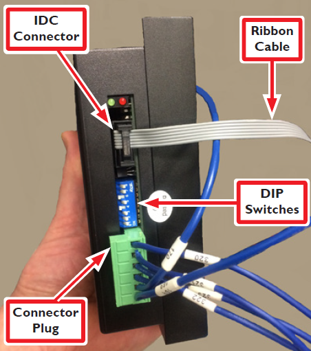
Figure 13
Locate Connector Plug on drive; this is for power (see Figure 13).
Install power and motor wires in Connector Plug with wire numbers visible; refer to Tormach technical document TD10173 (included) for wire connection details.
IMPORTANT! Wire identification is critical; for more information, refer to PCNC 1100 Power Wiring Overview and PCNC 770 Power Wiring Overview sections earlier in this document.
Match DIP switch (see Figure 13) settings on drive as detailed in technical document TD10173 (included).
Final Check Before Powering On
After assembly is complete, review wiring in detail:
Check closely to see that there are no individual strands of loose copper wire.
NOTE: A magnifying glass may help locate loose wires.
Refer to Electrical Connections PCNC 1100 and Electrical Connections PCNC 770 sections earlier in this document to confirm each of the wire numbers for the power wires.
Confirm the wire clamps in the Connector Plug (see Figure 13) are clamping on the copper wire and not on the plastic insulation around the copper wire.
Replace wire trough covers.
Plug in rotary table.
Power on mill according to Power Off/On Procedure detailed earlier in this document; the power LED on the newly installed driver module should light.
Run the control program. You should be able to jog the rotary table using the left and right arrow keys.
Basic Operation
Components of the Standard, Super Spacer, and Tilting tables are shown in Figure 14, Figure 15, and Figure 16.
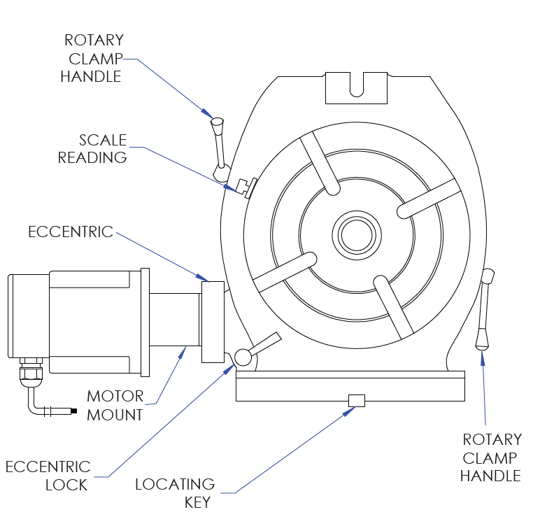
Figure 14: Standard Table
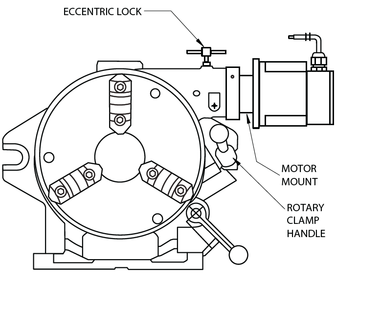
Figure 15: Super Spacer Table
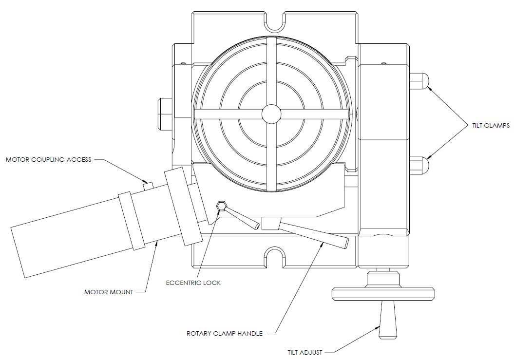
Figure 16: Tilting Table
IMPORTANT! Backlash should be adjusted prior to first use as detailed later in this document.
IMPORTANT! This product ships without oil and must be filled before being put into service. Operating this product without lubrication voids warranty. Refer to the Maintenance section for detailed instructions on how to lubricate Standard, Tilting, and Super Spacer rotary tables.
IMPORTANT! To avoid damage to the driver, power off the mill according to the Power Off/On Procedure detailed earlier in this document before connecting or disconnecting the rotary table.
Rotary Clamps: To keep the table from rotating during heavy milling operations, tighten the clamps with the clamp handles. The clamps should be loosened during motorized rotation to allow free rotation. If the clamps are locked during a move, correct position will likely be lost.
Tilt Clamps: The Tilting Table has two Tilt Clamps that are tightened to lock the tilt position; tighten prior to machining (see Figure 16).
Engaging and Disengaging Worm Drive: On Standard and Tilting tables, to disengage the worm gear so the table can be turned by hand, loosen the Eccentric Lock (see Figure 14), rotate the eccentric by turning the Motor Mount as far as it will rotate clockwise, and re-tighten the Eccentric Lock. To re-engage the worm, loosen the Eccentric Lock, rotate the motor mount as far as it will rotate counterclockwise, and tighten the Eccentric Lock.
Rotate the table slightly, if necessary, by hand so the worm gear can engage the ring gear. If the worm is not completely engaged, the table will exhibit excessive backlash.
On a Super Spacer Table, rotate the motor mount counterclockwise to disengage the ring gear and clockwise to engage it; tighten the Eccentric Lock.
Adjustable Reference Mark: (see Figure 17) Used to read angles directly off the table, the clamp holding it in place can be loosened to allow the pointer to be moved to an exact degree mark.
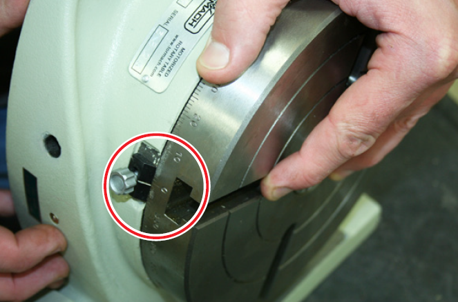
Figure 17
Vernier Scale
Used to align the angle of the Tilting Table from horizontal to vertical (see Figure 18).
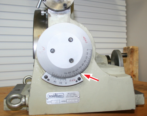
Figure 18
Use Vertical Setup: Chucks or fixtures to be used with the table in the vertical position are often easier to setup if the table is first horizontal and then moved to the vertical position.
Center Hole: The center hole (see Figure 19) is ground to an MT taper or a through bore to fit workholders. On tables with an MT taper, there also exists a shallow, concentric pilot hole which is used to locate a chuck or other tooling. See Workholding later in this document and refer to the Specifications table earlier in this document. Should coolant enter moving rotary table components, drain and flush with new oil.
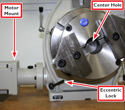
Figure 19
Wear: Try to distribute wear over the whole of the worm gear. When doing long runs of constant back and forth movement, occasionally reposition the table top and workholding fixture. Or if moves are close to 180°, continue rotating in the same direction to the start point rather than returning in the opposite direction. Or if the part permits, program the start point to change a few degrees each time.
Locking the Eccentric
Power is transmitted from the axis motor to the rotary table by worm gear at the end of the drive shaft. Use the Eccentric Lock (shown in Figure 14, Figure 15, and Figure 16) to stop the eccentric sleeve from rotating. This must be done before the worm drive is engaged to prevent the drive from disengaging during use.
Workholding
Direct Mount to Table
The 6” tables have 10 mm T-slots and the 8” tables have 12 mm T-slots. These can be used in combination with T-nuts and a clamp set to hold work directly to the table. Another option is to attach a vice or custom fixture plate to the table with bolts and T-nuts.
2-Jaw, 3-Jaw, and 4-Jaw Chuck
The 2-Jaw Chuck for a 6” Table (PN 32627) provides rapid prototype workholding. The set includes a self-centering 2-Jaw Chuck with an adapter plate and mounting hardware, including jaw plates. The 2-Jaw Chuck for an 8” Table (PN 32622) includes a MT3 adapter ring. The 3-Jaw Chuck is available in a 6” Table (PN 30292) and an 8” Table (PN 30291). The 4-Jaw Chuck is available in a 6” Table (PN 31721) and an 8” Table (PN 30293). Each chuck includes an adaptor plate and pin for mounting the chuck to the table and centering it to the rotational axis. Each chuck comes with both inside and outside interchangeable jaw sets.
5C Collet Adapter
A 5C Collet Adapter for 8” Table (PN 30294) includes an adaptor plate for mounting and centering the holder.
5C Collet Fixture
A 5C Collet Fixture for both 6” Table (PN 31414) and 8” Table (PN 31415). These mount directly to table T-slots.
MT2 Alignment Kit for ER32 Collet Fixture
This Morse Taper #2 Alignment kit for ER32 Collet Fixture (PN 34382) is available for use with 6” tables.
MT3 Alignment Kit for ER32 Collet Fixture
This Morse Taper #3 Alignment kit for ER32 Collet Fixture (PN 34383) is available for use with 8” tables.
MT3 Collet and Drawbolt
The 8” Table can accept an MT3 Collet, held in with a drawbolt. This can be used in combination with a Tormach Tooling System (TTS) tool holder as a low-cost method for holding slender bar stock. The 6” Table accepts an MT2 collet.
Maintenance
Lubrication
IMPORTANT! Rotary tables ship without oil and must be filled before initial use. Operating this product without lubrication voids warranty.
Lubrication-related locations for the Standard Rotary Table, Tilting Rotary Table, and Super Spacer Table are shown in Figure 20, Figure 21, and Figure 22. The standard rotary tables have an oil reservoir and Oil Points, better known as Ball Zerks (spring-loaded oil fittings), that must be filled with AGMA 2 gear oil or SAE 30 weight motor oil before first operation.
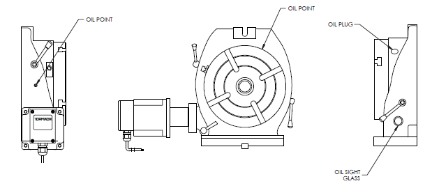
Figure 20: Standard Table
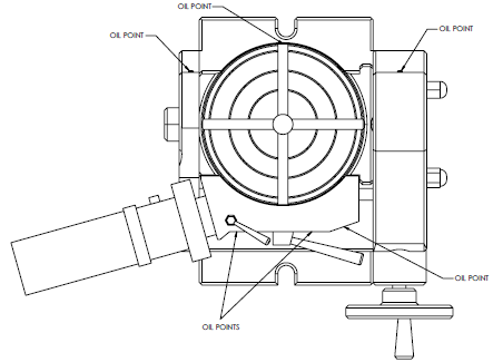
Figure 21: Tilting Table
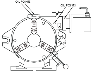
Figure 22: Super Spacer Table
NOTE: Do not use way oil on 4th Axis or any rotary products.
Ball Zerks (all tables)
Using a trigger-style oil can (included), fill the Ball Zerk oil fittings (see Figure 23 and inset). Depress the zerk’s spring-loaded ball with the tip of oil can and pump until there is back pressure.
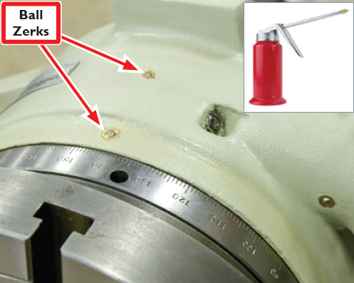
Figure 23
The oil reservoir (Standard table) is filled via the Oil Plug (see Figure 20 and Figure 24).
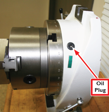
Figure 24
The oil reservoir should be filled with the table oriented (horizontal/ vertical) as it will be used. With the table in the horizontal position, fill the reservoir halfway up the Oil Sight Glass (see Figure 25). With the table in the vertical position fill the reservoir until oil just begins to leak out at the bottom of the table. If overfilled, the reservoir will slowly leak oil until it reaches the proper level.
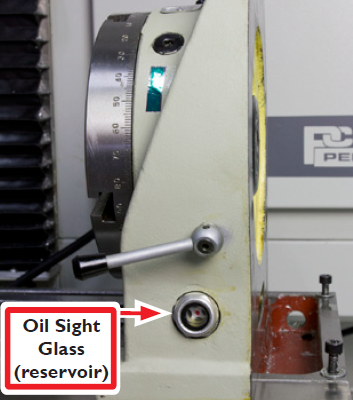
Figure 25
NOTE: When the oil reservoir is filled with the rotary table in the horizontal position, and then the rotary table is shifted to a vertical position, oil will leak out.
Place the rotary table in a pan or on a stack of newspaper until the excess oil has drained out (this many take a day or two). The rotary table can be used while oil is leaking out. Tilting Tables have six Oil Points, while Super Spacer tables have four. Neither table has an oil reservoir like the Standard Table.
IMPORTANT: Because Tilting and Super Spacer tables do not have an oil reservoir; frequent oiling is required.
Adjusting Backlash
CAUTION! Pre-mature Rotary Table Wear: Be sure to adhere to backlash adjustment procedures. Failure to do so could result in machine damage (pre-mature wear on rotary table’s ring and worm gear).
Backlash is an important element in managing overall accuracy. The rotary table has a number of internal sliding surfaces that depend on a hydrodynamic oil film for low friction and long life. Similar to the adjustments of the lead screw nut and gibs (on mill or lathe), adjustment of clearances between internal moving parts seeks common ground between extreme precision and long life.
If backlash is adjusted to zero, the worm screw and other parts are subject to excessive wear, friction, and consequently, table stalling. As the screw turns, the oil shears off at the gear interface – with no film to protect against metal-to-metal wear. Correctly adjusted backlash provides both long life and a minimum of backlash.
Backlash is adjusted by positioning of the Backlash Adjustment Screw. For the Standard Table, see Figure 26; for the Tilting Table, see Figure 27; and for the Super Spacer Table, see Figure 28.
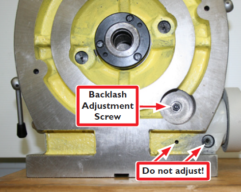
Figure 26: Standard Table
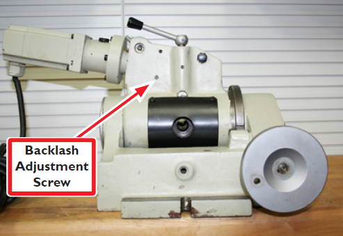
Figure 27: Tilting Table
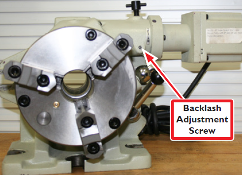
Figure 28: Super Spacer Table
The Backlash Adjustment Screw is accessed by removing the protective cover screw on top of it, or loosen a jam nut.
Loosen Backlash Adjustment Screw six turns counterclockwise.
Disengage Eccentric Lock and clamp handles.
Engage motor/worm gear by grasping it and rotating it fully (counterclockwise on Standard and Tilting tables; clockwise on Super Spacer Table). Verify the table does not turn; the table will not turn if the motor is engaged.
With counterclockwise pressure on the motor using one hand (clockwise on Super Spacer table), slowly tighten the set screw until resistance is felt to the pressure.
NOTE: Pay attention as this resistance is subtle.
At this point, the set screw is just against the worm drive. Tighten the set screw approximately 1/4 turn, which will rotate motor slightly. This step creates a gap between table and worm gear for an oil film.
Alternatively, to set backlash by the numbers, adjust for a minimum backlash of 30 arc-seconds. Measured at the outer circumference of an 8” diameter circle with a dial indicator, 30 arc-seconds will be 0.0006” of lost motion.
Setting backlash to 60 arc-seconds will sustain a thicker oil film, yielding lower friction and longer life. This would be 0.0012” on the outside of an 8” circle.
Setting backlash greater than 90 arc-seconds (1.5 arc-minutes) is not recommended; it will do nothing to improve the life of the mechanism and can result in chatter during machining operations.
Replace cover screws.
Inspect or Tighten Motor Coupling
In the rare instance where a motor coupling is loose or cracked, this will cause the table to slip relative to motor rotation and subsequently lose position.
Remove the set screw on the motor mount (see Figure 29).
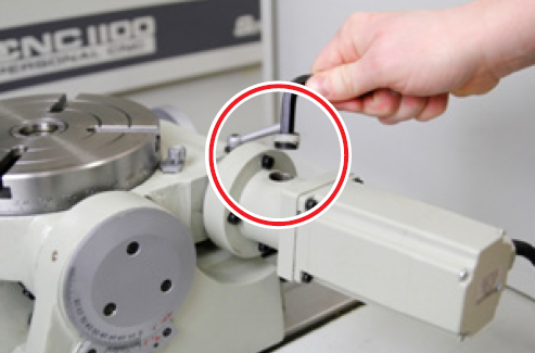
Figure 29
Jog the motor until the first of two coupling screws inside motor mount can be accessed.
Tighten screws on coupling.
Motor Coupling Removal
If removal is required, loosen the socket head cap screw and the set screw on the motor coupling; do not remove (see Figure 30).
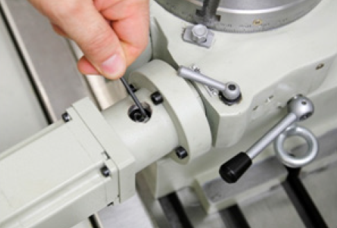
Figure 30
Detach the motor from the motor mount by removing four mounting screws (see Figure 31). Remove the motor with the coupling still attached (see Figure 32).
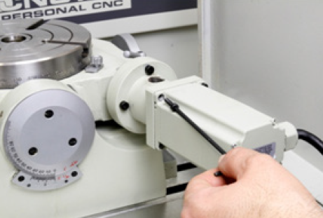
Figure 31
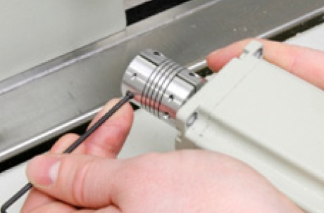
Figure 32
With motor out, inspect the coupling and tighten the remaining coupling screws on motor shaft.
If coupling is broken, remove motor coupling and replace with 6” rotary table coupling (PN 31840) or 8” rotary table coupling (PN 30715).
Ensuring Water/Coolant Resistance
The electric motor is sealed against cutting fluids. However, the motor, motor cable, and the seam between the rotating table and the base casting should not be subject to constant coolant flow, or exposed to high-pressure coolant jets. Keep the motor body painted, particularly the magnetic laminations in the center. To prevent rust from trapped, water-based coolants on the table base, apply a thin film of oil (WD-40® or similar) to surfaces before set up.
There are several steps that ensure the rotary table remains resistant to water/coolant. Use thread seal tape (PTFE) to seal the set screw on the motor mount (see Figure 29). Position the motor so its cord points downward when the motor is engaged. Depending on the operational position
(horizontal or vertical), this may require repositioning of the motor with respect to the motor mount. The rotary table is designed to operate in the presence of coolant, but not when submersed in coolant. If coolant is dripping over the edge, this is rarely a problem. If there is a serious external coolant flow, and the joint between the rotating table and the stationary body is submersed, this is a problem.
There is an oil distribution system internal to the rotary table. As the table turns it carries oil over the worm gear. This distribution system does not cover the sliding joint between the rotating table and the body. That joint is similar to the slideways of a mill and has a large, flat surface supported by an oil film. The oil port on the edge of the rotary table (and on the body itself) provides oil to these sliding surfaces. Oiling at those ports on occasion is analogous to pulling the pump handle for oil distribution on the mill. It is important because this film of oil is essential to keep water/coolant away from the sliding joint. If running coolant, then it becomes even more important to occasionally pump some oil in at the oil ports. A combination of heavy flood coolant and never oiling the sliding joints, will result in coolant entering the table. If this happens, simply drain it out and refill it with one of the following: AGMA 2 gear oil, or SAE 30 weight motor oil.
Coolant contains anti-corrosion agents which protect the table surfaces. A small amount of coolant and oil generally forms an emulsion, with the oil view port showing a milky fluid inside. If the oil gets milky, or if you can see raw coolant inside, drain it and refill with new oil.
Worm Axial Adjustment
To adjust for wear in the worm gear, the lock nut must be adjusted. Location of the lock nut is shown in the exploded views later in this document.
Follow the steps in the Inspecting/Removing Motor Mount and Coupling section earlier in this document to remove motor and coupling.
Apply a dab of grease to the back side of the spacer. Location of the spacer is shown in the exploded views later in this document.
Using two spanner wrenches (PN 30485), tighten (or loosen) the lock nuts (see Figure 33). Adjust the spacer nut (PN 35557) so there is no axial play when turned by hand (see Figure 34) in the worm shaft and the shaft moves freely; Do not overtighten the locknut.
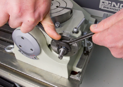
Figure 33
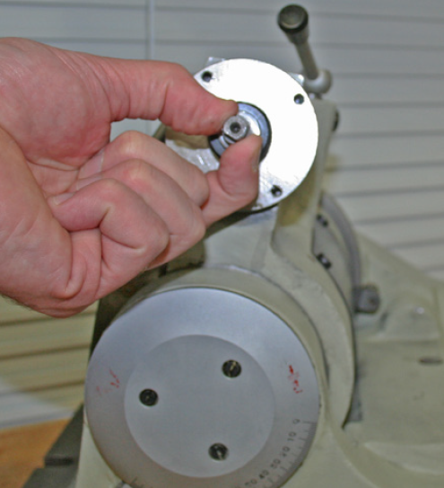
Figure 34
Table Adjustment
On the Standard, Tilting, and Super Spacer tables, test for correct axial adjustment by disengaging the worm and rotating the table by hand; slight drag should be felt. If not, loosen the three screws in the Retaining Plate (see Figure 35) two turns with a flathead screwdriver. Next, tighten or loosen Retaining Plate with an Adjustable Pin Spanner Wrench (PN 31118). Rotate the plate clockwise to increase drag and counterclockwise to decrease drag. Location of the aforementioned parts are shown in exploded views later in this document.
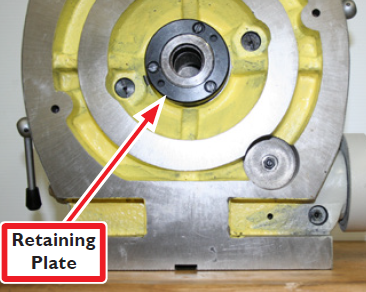
Figure 35
Engaging Locking Lugs on Tilting Table
The Tilting Table has two locking lugs. When intentionally or inadvertently moved out of position, the table will not tilt within the full range of motion.
In particular, the more interior locking lug is difficult to realign/fit with the recessed grove. To manually align this lug, manually crank the handle and move the table to a position that allows access to the displaced part.
Using fingers or a small tool, move the locking lug back into place. In its correct orientation, only the cap of the lug will be visible (see Figure 36 and Figure 37).
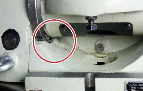
Figure 36: Lug In
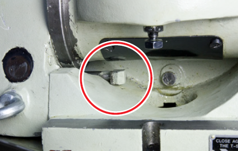
Figure 37: Lug Out
Troubleshooting
Problem: 4th Axis will not move, but other axes operate properly
Possible Cause | Probability | Action to Identify Cause of Problem | Discussion |
No power to the table | High | Inspect cord | Ensure motor cord is plugged in to 4th Axis socket. |
Loose wires or ribbon cables | Medium | Remove and inspect power and ribbon cable connectors and wires entering and exiting the A-axis drive at both ends. | Tighten loose wires |
Table lock(s) engaged | High | Release lock(s) | Standard Table has two locks, Tilting Table has one. |
Motor coupling loose or cracked | Low | Inspect and tighten coupling bolts or replace coupling if necessary. | Refer to Inspecting/Removing Motor Coupling section |
Worm gear not engaged | High | Engage gear | The gear operates on an eccentric pivot. To engage gear manually, twist motor and motor coupling housing counterclockwise and lock into place with lever (Standard and Tilting tables), and or locking bolt (Super Spacer Table). |
Worm gear out of adjustment | Medium | Inspect worm gear adjustment screw and worm gear shaft locknut | Refer to Adjusting Backlash and Worm Axial Adjustment |
A blown fuse on the DC bus board | Low | Inspect fuse | A blown fuse is usually the result of a bad drive. If a fuse is replaced and it immediately blows, suspect a bad drive or bad wiring to the drive. |
Problem: 4th Axis will not move, but other axes operate properly
Possible Cause | Probability | Action to Identify Cause of Problem | Discussion | ||||||||||||
Defective motor or motor connection | Low | Inspect motor and leads | Remove the motor leads from the connector plug on the drive. Measure the resistance of motor windings and compare to values in the table below. If the resistance is out of range, check wiring carefully. If the wiring is good and the resistance readings are out of range, the motor is defective. A-axis
| ||||||||||||
Exact stop mode used in program, G-code G61 | Low | Examine G-code | Use of Exact Stop Mode has been shown to cause a loss of steps on older mill versions. Avoid using this mode if at all possible. Try slowing down the rates of acceleration and deceleration by a factor of 10 to start and stop more smoothly. |
Problem: Table Losing Position
Possible Cause | Probability | Action to Identify Cause of Problem | Discussion |
Backlash out of adjustment | Medium | Inspect backlash | Refer to Adjusting Backlash section |
Coupling screws not tight | Medium | Inspect motor coupling | Follow steps 1-6 in Inspecting/ Removing Motor Coupling section. Completely remove motor coupling from motor. The coupling must be removed from motor in order to inspect all four set screws. |
Coupling access plug in too far. | Low | Inspect plug | There is an access port used to tighten the worm-motor coupling. If the plug in the access hole is in too far, it binds on the coupling. |
Problem: Table Rotation Direction Incorrect
Possible Cause | Probability | Action to Identify Cause of Problem | Discussion |
Motor Wiring | Medium | Check motor wiring | Set motor wiring per Electrical Installation section. Reversing the leads on either coil will change motor direction. |
Problem: Table Rotates Correctly in One Direction and Shutters in the Other Direction
Possible Cause | Probability | Action to Identify Cause of Problem | Discussion |
Incorrect DIP switch settings | High | Check the DIP switch settings | Check to make sure that the DIP switch settings are sect correctly for your motor. Refer to TD10173 for information (provided). |
Parts List
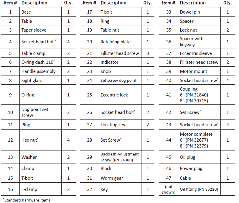
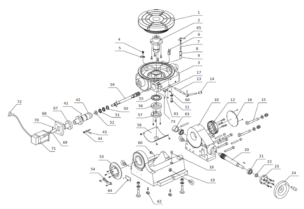
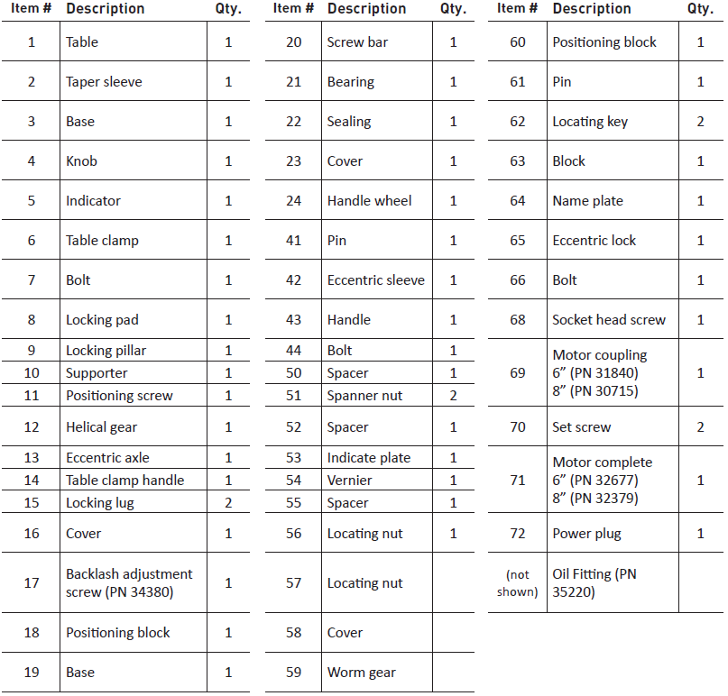
Standard Rotary Table (exploded view)
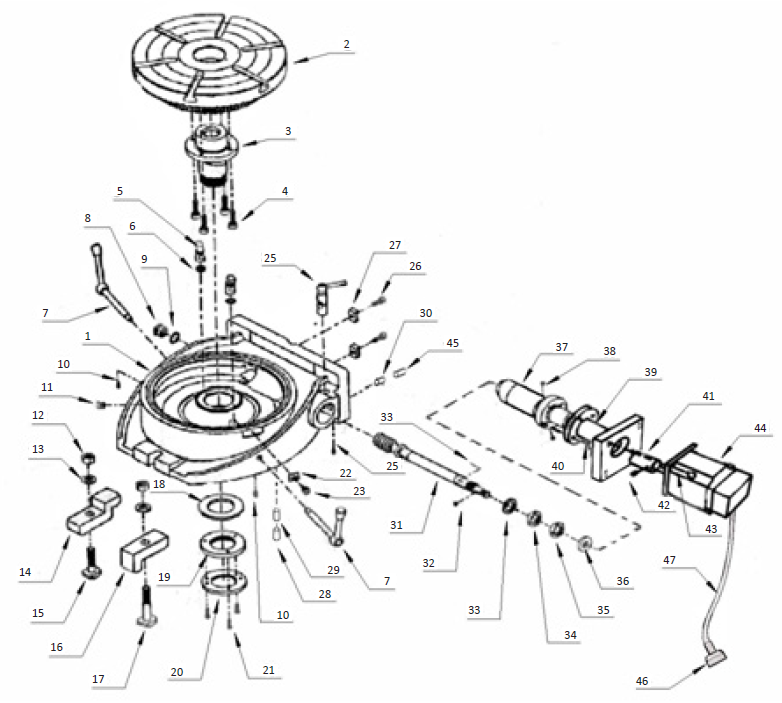
Standard Rotary Table Parts List
Tilting Rotary Table (exploded view)
Tilting Rotary Table Parts List
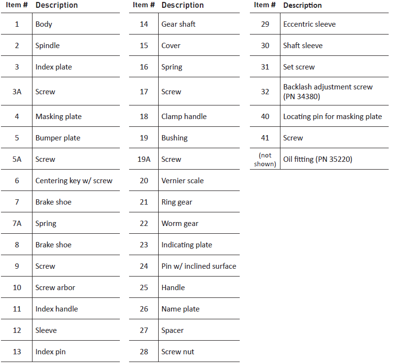
Super Spacer Rotary Table (exploded view)
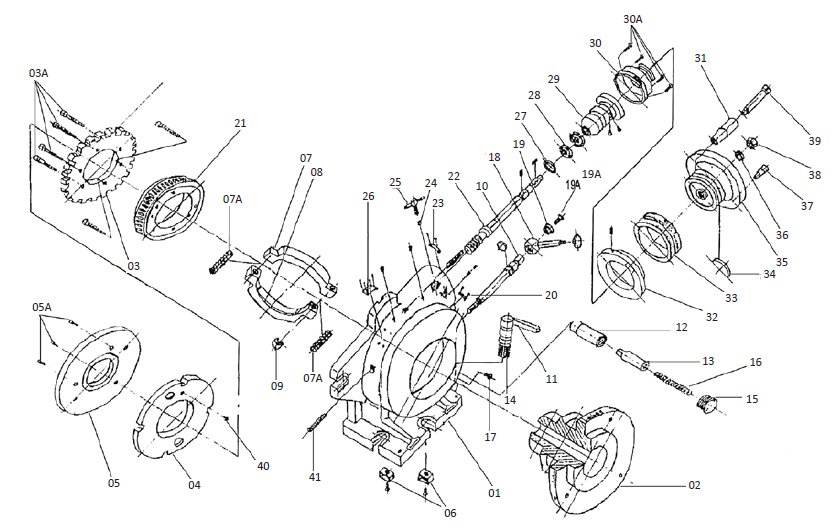
Super Spacer Rotary Table Parts List
Integrating with Custom System
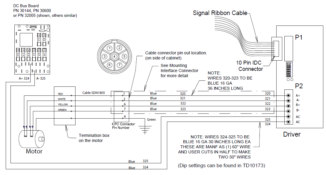
The Motor, Cable, Plug, and Pinout are shown in Figure 38. Motor wiring is shown in the corresponding Motor Wiring Chart below.
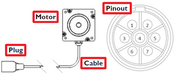
Figure 38
The cable plug is: AMP CPC series 211400-1
The mating receptacle is: AMP CPC series 211398-1
Motor Wiring Chart
Plug Pin | Cable | Motor Connection | Motor Function |
1 | White 1 | Red | Phase A+ |
2 | Black 1 | White | Phase A- |
3 | NC | — | NC |
4 | Shield | Case | Case ground |
5 | NC | — | NC |
6 | White 2 | Yellow | Phase B+ |
7 | Black 2 | Green | Phase B- |
To view a PDF version of your manual, go to Tormach document TD10374.
If you have additional questions, we can help. Create a support ticket with Tormach Technical Support at tormach.com/how-to-submit-a-support-ticket for guidance on how to proceed.