Overview of Work Offsets on a CNC machine
A work offset is a location in 3D-space on a CNC machine that relates the CNC program to a machine tool location. On a 3-axis machine, a work offset locates the X0Y0Z0 coordinate of the program. You can place a work offset anywhere in 3D-space; however, it is almost always a located inside the work envelope of the machine.
Many CNC machines can store more that one work offset at a time. Each work offset is assigned to a G code; machine coordinates displayed are relative to the active work offset. The active work offset can be determined by looking at the status line of the PathPilot display:

PathPilot can store up to 500 work offsets:
|
G54 |
Primary work offset (1) |
|
G55-G59 |
Secondary work offsets (2-6) |
|
G59.1 - G59.3 |
Additional work offsets (7-10) |
|
G54.1 P10 - G54.1 P500 |
Additional work offsets (11-500) |
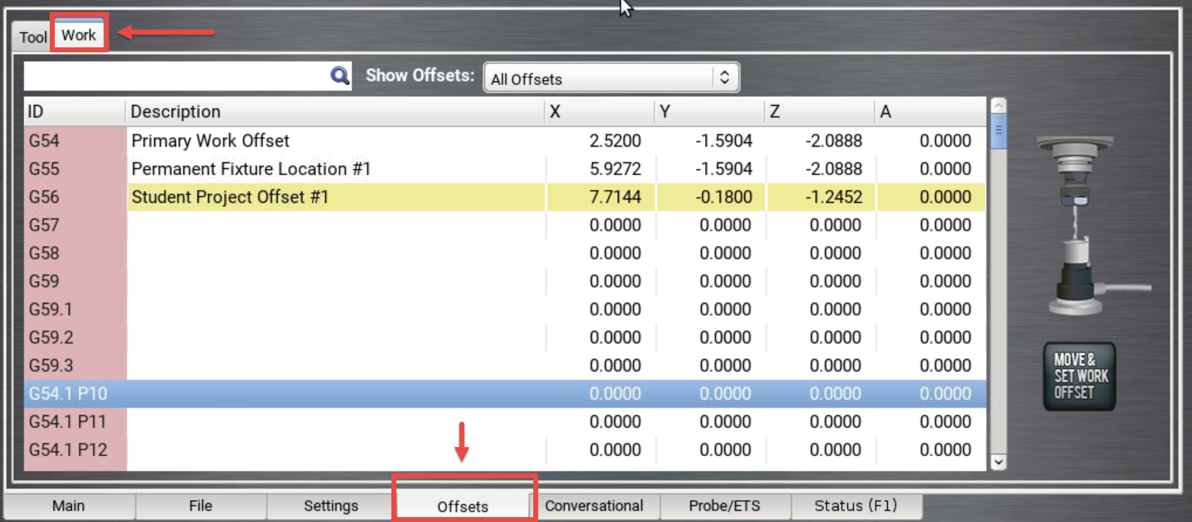
The actual Work Offsets coordinates are stored in the work offset table, which is found in the Offsets tab:

The X, Y, and Z coordinates associated with each offset are the distance of the offset from the reference location of the machine. While it is possible to edit the coordinates in the work offset menu, it is not part of a common workflow.
In practice, the majority of common programming is done using the only the primary work offset, G54. Secondary work offsets are typically used when machining multiple sides on a part in the single program, or when machining multiple parts. Additional work offsets are available for complex projects and workflows.
How to Set a work offset in PathPilot
To set the location of a work offset in PathPilot, use the following procedure:
-
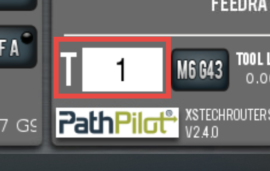
Make sure the machine is referenced, and the active tool (the T field) in PathPilot is the same as the tool in the spindle:

-
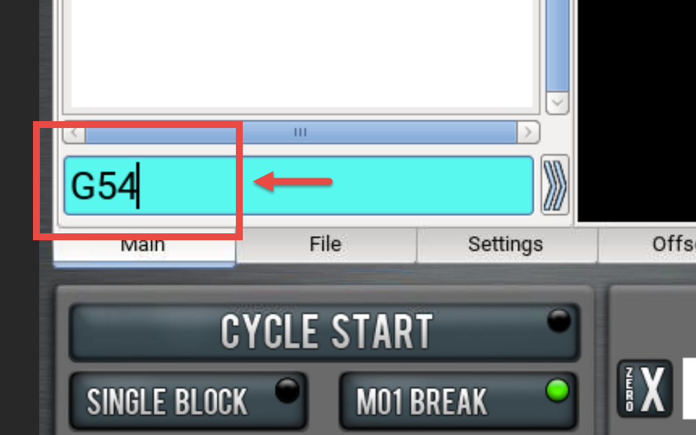
Activate the desired work offset by typing it into the MDI field and pressing Enter.

-
Move X-, Y-, and Z-axes to position the center of the tool tip at the intended work offset location.
-
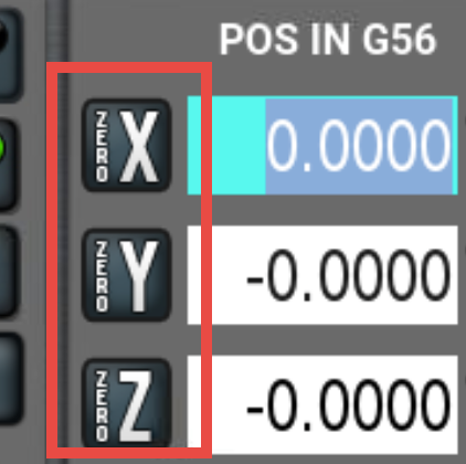
Press Zero X, Zero Y, and Zero Z Buttons. The work offset is now set.

How to Find a Work Offset in a CNC Machine
There are a number of techniques that can me used to set work offsets on a CNC machine. When selecting a method, you must consider several factors:
-
Accuracy - does the method let you
-
Precision - does the method give the same result when repeated? If not, what is the expected error in measurement.
-
Ease of locating- is the method easy to use, or does it require complex or specialized tool?
-
Re-findability - can the work offset be found accurately during or after the part has be cut?
Method 1: Eyeball
Simply position the tip of the tool as close to the intended work offset location as you can discern by sight and zero each axis to set the work offset.
Method 2: Paper
Position the tool so it is close to the intended work offset location. Place a thin strip of paper between the tool and the work surface and slowly move the tool towards the surface while gently wiggling the paper. When the paper starts to drag as it catches between the tool and the work surface, stop movement and zero the axis. The method works best for setting the Z-axis work offset.
Method 3: Dust Off
Turn the spindle on to desired speed (i.e.; 10,000 RPM). Slowly move the tool towards the work surface and observe until you notice the smallest amount of machining dust (generally also accompanied by a change in machining noise). Stop movement and zero the relevant axis.
