Purpose
This document gives instructions on installing the 1100M+ Servo Upgrade Kit on a mill.
Product Information
Product: 1100M+ Servo Upgrade Kit (PN 39274)
|
Quantity |
Description |
|
1 |
1100M+ Enclosure Decal (PN 39393) |
|
1 |
1100M+ Electrical Cabinet Decal (PN 39392) |
|
3 |
8-Position Terminal Block (PN 32877) |
|
1 |
Sikaflex (PN 51481) |
|
1 |
Cord Grip (PN 38758) |
|
1 |
Cord Grip Nut (PN 30806) |
|
4 |
Cable Gland (PN 35974) |
|
1 |
Dielectric Grease (PN 38268) |
|
3 |
Flex Conduit Fitting (PN 30628) |
|
4 |
M5 × 0.8 - 20 mm Socket Cap Screw (PN 30357) |
|
4 |
M5 Flat Washer (39305) |
|
4 |
M5 Lock Washer (PN 30534) |
|
1 |
M5 Tap (PN 33420) |
|
1 |
M5 Tap Drill (PN 33641) |
|
1 |
X-Axis Servo Control Cable (PN 39398) |
|
1 |
Y-Axis Servo Control Cable (PN 39399) |
|
1 |
Z-Axis Servo Control Cable (PN 39400) |
|
1 |
X-Axis Servo Power Cable (PN 39402) |
|
1 |
Y-Axis Servo Power Cable (PN 39403) |
|
1 |
Z-Axis Servo Power Cable (PN 39404) |
|
7 |
Spade Electrical Connector (PN 30610) |
|
1 |
X-Axis Flex Conduit (PN 30627) |
|
1 |
X-Axis Motor Cover Assembly (PN 39283) |
|
1 |
X-Axis Servo Motor (PN 38404) |
|
1 |
Y-Axis Servo Motor (PN 38701) |
|
1 |
Z-Axis Brake (PN 38399) |
|
1 |
Z-Axis Servo Motor (PN 38405) |
NOTE: If any items are missing, we can help. Create a support ticket with Tormach Technical Support at tormach.com/how-to-submit-a-support-ticket for guidance on how to proceed.
Required Tools
This procedure requires the following tools. Collect them before you begin.
-
1-2-3 block (or similar)
-
Adhesive tape
-
Ammonia-free window cleaner (or similar)
-
Bar clamp
-
Center punch
-
Channellock pliers
-
Electric drill
-
Electrical tape (or similar)
-
Flat-blade screwdriver
-
Flat-blade screwdriver, small
-
Ladder (about 3 ft)
-
Marker
-
Metric hex wrench set
-
Mild degreaser (like Simple Green®)
-
Needle-nose pliers
-
Paper towels
-
Phillips screwdriver
-
Plastic squeegee (or similar)
-
Tap handle
-
Two-by-four, two (or similar 3-in. block of wood)
-
Wire crimper
-
Wire stripper
Before You Begin
-
Automatic Oiler Required You must confirm that the mill is regularly oiled. If you don't, there's a risk of motor faults. Use an Automatic Oiler Kit: 230 Vac (PN 38255).
-
Clean Machine Clean all chips and swarf from the machine with a bench brush and a dustpan.
NOTE: If you start with a clean machine, it's easier and safer to find and pick up any parts or fasteners that might drop during the procedure.
-
ECMv1.5 Update Kit Required If you don't have an ECMv1.5 or later control board, you must first install the ECM1v1.5 Replacement Kit for 1100M and 770M (PN 39718). For information, see the product's documentation.
-
Keep All Hardware To install the servo motors, you'll reuse many items currently used on the machine. Keep all hardware unless you're specifically instructed to discard it. If you don't, there's a risk that you won't have the hardware you need to complete the installation.
-
PathPilot v2.2.X or Later Required Only PathPilot v2.2.X and later has settings required to use a servo motor mill configuration. For information, go to "Update PathPilot".
Update PathPilot
Before you begin to install this kit, you must verify that the PathPilot controller is updated to the latest version of PathPilot. This is because only PathPilot v2.2.X and later has settings required to use a servo motor mill configuration.
To update PathPilot, do one of the following:
Download and Install an Update File from the Controller
-
Confirm that the PathPilot controller is powered on and out of Reset mode.
-
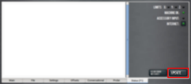
Downloading and installing an update file requires an Internet connection. From the Status tab, confirm that the Internet button LED light is on. (To configure the network, select the LED light.) Then, select Update.

-
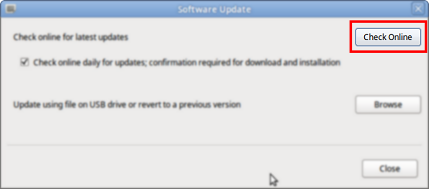
From the Software Update dialog box, select Check Online.
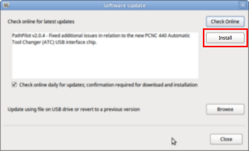
-
Select Install.
-
The update file is downloaded, and a notification dialog box displays.
-
From the dialog box, select OK.
The update file is installed on the PathPilot controller. -
Follow the on-screen instructions to restart the PathPilot controller.
Install an Update File from a USB Drive
-
From the PathPilot support center, download the most recent PathPilot update file.
-
Transfer the PathPilot update file to a USB drive.
-
Put the USB drive into the PathPilot controller.
-
Confirm that the PathPilot controller is powered on and out of Reset mode.
-
From the Status tab, select Update.
-
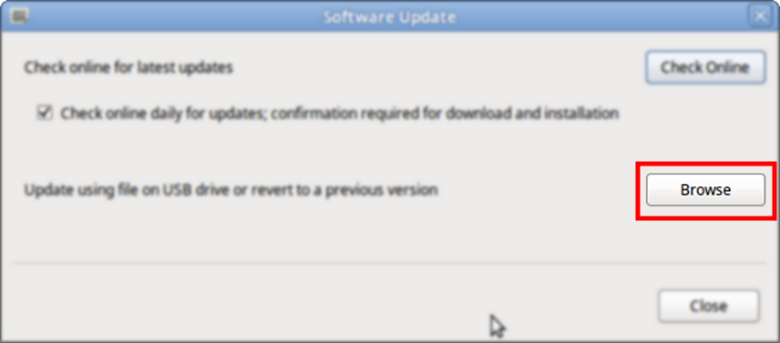
From the Software Update dialog box, select Browse.
-
From the Browse dialog box, select USB.
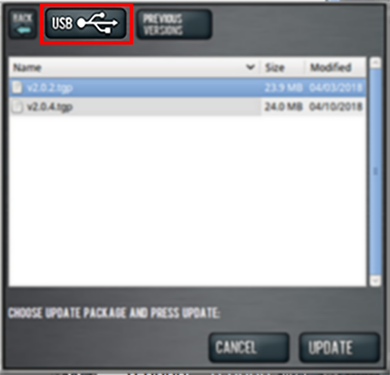
-
Select the desired update file, and then select Update.
The update file is installed on the PathPilot controller. -
Follow the on-screen instructions to restart the PathPilot controller.
Removal
Complete the following steps in the order listed:
Prepare the Machine
-
If you have any tooling in the spindle, remove it.
-
Remove any workholding from the machine table.
-
Loosen the four screws securing the drip guard to the front of the machine table with a 4 mm hex wrench. Then, remove the drip guard and set it aside.
-
Remove the tool tray from the machine table with a 4 mm hex wrench. Set aside the screws and the tool tray.
-
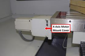
Identify the X-axis motor below the left side of the machine table.
-
Identify the Y-axis motor on the rear of the machine.
-
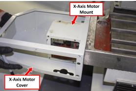
Remove the motor mount cover from the X- and Y-axis motor with a 3 mm hex wrench. Set aside the screws and the motor mount cover.
-
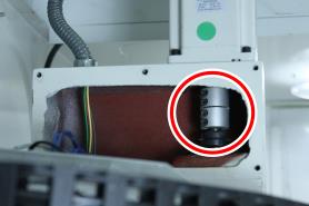
Identify the four set screws on both motor couplers, and examine the direction to which they point. To easily access the set screws, they must point toward you.
-
Depending on the direction in which the set screws are pointing, do one of the following:
-
Set Screws Pointing Toward You Go to Step 10.
-
Set Screws Pointing Away from You This indicates that the machine table is positioned incorrectly. Move the machine table until the set screws on both the X- and Y-axis motor coupler are pointing toward you.
-
WARNING! Crash Hazard: You must support the spindle head as described in this document before you make any mechanical or electrical adjustments to the spindle head. (For example, loosening the set screws on the Z-axis motor coupler.) If you make adjustments without first supporting the spindle head, it could result in the spindle head crashing on the machine table.
-
To prevent the spindle head from dropping onto the machine table, put a set of two-by-fours (or similar 3-in. block of wood) on the machine table so that it's:
-
Below the spindle flange
-
Clear of the (optional) coolant nozzles
-
11. Slowly jog the Z-axis down (-Z) until the spindle flange is on the set of two-by-fours.
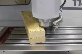
NOTICE! Don’t put the spindle nose on the set of two-by-fours. If you do, it could add unnecessary force to the spindle bearings, and damage the machine components.
-
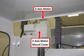
Identify the Z-axis motor mount cover plate below the Z-axis motor on the machine column.
-
Remove the motor cover from the machine column with a 3 mm hex wrench. Set aside the screws and the motor cover.
-
Identify the four set screws on the Z-axis motor coupler inside the Z-axis motor mount, and examine the direction to which they point. To easily access the set screws, they must point toward the left side of the machine once the Z-axis is lowered.
-
Depending on the direction in which the set screws are pointing, do one of the following:
-
Set Screws Pointing Left Go to Step 16.
-
Set Screws Not Pointing Left This indicates that the set of two-by-fours is too short for your machine. Repeat Steps 10 through 15 with a different block of wood.
-
WARNING! Electrical Shock Hazard: You must power off the machine before making any electrical connections. If you don't, there's a risk of electrocution or shock.
-
Power off the machine and the PathPilot controller.
-
Push in the machine's red Emergency Stop button, which removes power to motion control.
-
From the PathPilot interface, select Exit.
-
Turn the Main Disconnect switch to OFF on the side of the electrical cabinet.
-
Remove the power plug(s) from the wall outlet. If your system is hardwired, isolate the machine by opening its circuit breaker(s).
-
Follow correct lockout/tagout procedures.
-
Remove the Stepper Motor Drivers
NOTICE! Only remove wires as instructed in this procedure. If you don't, there's a risk that you could remove wires required for future accessories (like a 4th axis).
-
Open the electrical cabinet door.
NOTE: Depending on the location of your machine and the amount of space you have to work in, you may it easier to first remove the electrical cabinet door and the ground screw.
-
From inside the electrical cabinet, remove all of the wire troughs and set them aside.
-
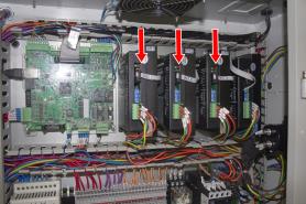
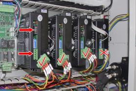
Identify the stepper motor drivers.
-
Remove the green connectors and the ribbon cable connectors from the X, Y, and Z stepper motor drivers.
NOTE: If you have an (optional) 4th axis, don’t remove any wires from its driver (in the electrical cabinet, it’s furthest to the right).
-
Remove the X, Y, and Z stepper motor drivers with a Phillips head screwdriver. Discard all three drivers and their six screws.
-
Find the three ribbon cables that you removed in Step 4, and then put them into the wire trough.
-
Find the three green connectors that you disconnected in Step 4, and remove all of the wires from each connector with a small, flat-blade screwdriver. Discard all three connectors.
-
Identify the DC-BUS board.
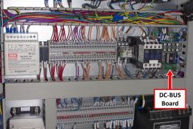
9. Remove wires 210, 211, 220, 221, 230, and 231 from the DC-BUS board with a needle-nose pliers.
NOTE: Pull the blue spade connector, not the wire itself.
-
Remove all of the stepper motors’ wires from the wire troughs. There are 15 in total:
-
210 through 214
-
220 through 224
-
230 through 234
-
-
Wires 210, 211, 220, 221, 230, and 231 are now completely disconnected from the electrical cabinet; discard them.
-
Identify the Z-axis brake wires: follow wire 400 and wire 435 (both black) from the Z-axis brake into the electrical cabinet.
-
When you install the new Z-axis brake that's provided with this kit, you must make its wire connections in place of the original Z-axis brake wires. Record the current location for both wire 400 and wire 435 in the electrical cabinet.
-
Remove wire 400 and wire 435 from the electrical cabinet with a small, flat-blade screwdriver. Then, remove both wires from the wire troughs.
-
Remove the Z column panel with a 3 mm hex wrench. Set aside the screws and the column panel.
-
Carefully move the following wires out of the electrical cabinet, through the Z column opening, and then discard them:
-
212 through 214
-
222 through 224
-
232 through 234
-
400
-
435
-
-
Remove the sleeves from each of the three groups of wires, and set them aside.
Remove the Stepper Motors
Remove the X-Axis Stepper Motor
-
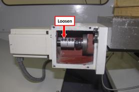
On the motor coupler, loosen the two set screws that are closest to the motor with a 3 mm hex wrench.
NOTE: If you loosen all four set screws at the same time, the coupler could disconnect from the ball screw shaft.
-
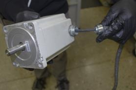
On the motor, identify the flex conduit. Then, follow it to the machine column, and remove it from the machine column with Channellock pliers.
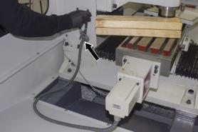
-
Pull the wires from the motor out of the machine column.
-
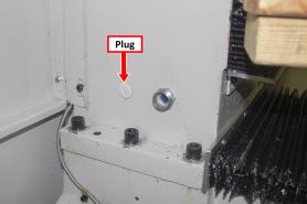
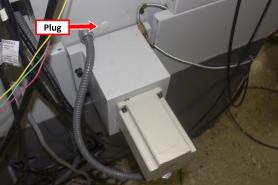
Remove the plug (by the flex conduit fitting) from the machine column with a flat-blade screwdriver. Discard the plug.
-
Remove the motor from the machine with a 4 mm hex wrench.
-
Remove the flex conduit from the X-axis motor, and then pull the wires through the flex conduit.
-
Set aside the mounting screws, washers, and flex conduit for the installation of the servo motors. Then, discard the motor and its wiring.
NOTE: Separate the X-axis flex conduit from the other motors' flex conduits. It's easy to confuse them, and you only need the X-axis' flex conduit for the installation of the servo motors.
Remove the Z-Axis Stepper Motor
WARNING! Crash Hazard: You must support the spindle head as described in this document before you make any mechanical or electrical adjustments to the spindle head. (For example, loosening the set screws on the Z-axis motor coupler.) If you make adjustments without first supporting the spindle head, it could result in the spindle head crashing on the machine table.
-
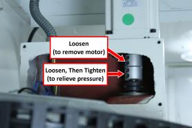
To relieve tension from the ballscrew, loosen the two bottom set screws on the motor coupler with a 3 mm hex wrench, and then re-tighten them.
-
On the motor coupler, loosen the two top set screws with a 3 mm hex wrench.
NOTE: If you loosen all four set screws at the same time, the coupler could disconnect from the ball screw shaft.
-
On the motor, identify the flex conduits. Then, follow them to the machine column, and remove them from the machine column with Channellock pliers.
-
Pull the wires from the motor out of the machine column.
-
Remove the flex conduit fittings from the machine column with Channellock pliers. Discard the fittings.
-
Remove the motor from the machine with a 4 mm hex wrench.
-
Set aside the mounting screws and washers for the installation of the servo motors. Then, discard the motor and its wiring.
Remove the Y-Axis Stepper Motor
-
On the motor coupler, loosen the two set screws that are closest to the motor with a 3 mm hex wrench.
NOTE: If you loosen all four set screws at the same time, the coupler could disconnect from the ball screw shaft.
-
On the motor, identify the flex conduit. Then, follow it to the machine column, and remove it from the machine column with Channellock pliers.
-
Pull the wires from the motor out of the machine column.
-
Early 1100M mills require different routing for the Y-axis motor. Depending on your machine's serial number, do one of the following:
MA10267 and Above Do the following:
a. Remove the plug (by the flex conduit fitting) from the machine column with a flat-blade screwdriver. Discard the plug.
b. Remove the flex conduit fitting from the machine column with Channellock pliers. Discard the fitting.
c. Remove the motor from the machine with a 4 mm hex wrench.
d. Set aside the mounting screws and washers for the installation of the servo motors. Then, discard the motor and its wiring.
MA10266 and Below Do the following:
a. Remove the flex conduit fitting from the machine column with Channellock pliers. Discard the fitting.
b. Remove the motor from the machine with a 4 mm hex wrench.
c. Set aside the mounting screws and washers for the installation of the servo motors. Then, discard the motor and its wiring.
Installation
Complete the following steps in the order listed:
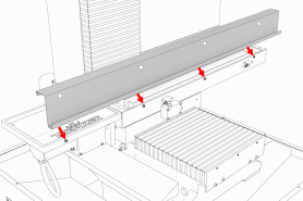
Prepare the Machine for the X-Axis Motor Cover
On the X-axis motor mount, you must drill and tap four holes that you'll use to secure the X-axis motor cover. Use the template (provided in this document) to drill and tap the holes in the correct location.
To prepare the machine for the X-axis motor cover:
-
Clean the surface of the X-axis motor mount with a mild degreaser (like Simple Green®).
-
Find the X-axis motor cover provided with this kit.
-
Remove the six screws securing the plate to the motor cover with a 3 mm hex wrench, and set all aside.
-
Find the X-axis motor mount template provided in this document.
-
Align the template on the motor mount as shown in the following image. Then, secure the template to the motor mount with adhesive tape.
-
Repeat Step 4 to secure the second template to the back of the motor mount.
-
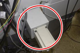
To confirm that the template is correctly positioned, temporarily align the X-axis motor cover on the motor mount. The X-axis motor cover must be against the machine table (as shown in the image), and the surface between the motor mount and the X-axis motor cover must be flush.
-
Set aside the X-axis motor cover.
-
Put a mark in each of the template's four holes on the motor mount with a center punch.
-
Remove the templates from the motor mount.
-
Drill each hole that you marked in Step 9 with the drill bit provided with this kit. Each hole should be approximately 3/4-in. deep.
-
Tap each hole that you drilled in Step 11 with the tap provided with this kit.
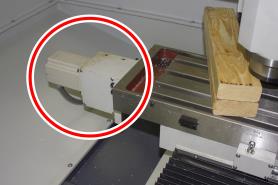
Install the Servo Motors
Install the X-Axis Servo Motor
-
Find one of the flex conduit fittings provided with this kit.
-
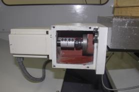
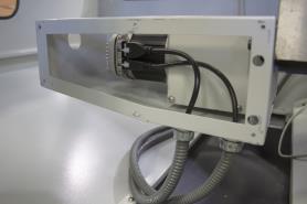
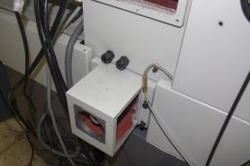
Install the flex conduit fitting in place of the plug that you removed in "Remove the Stepper Motors", as shown in the following image.
-
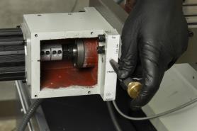
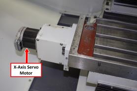
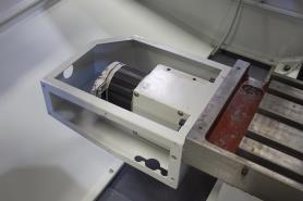
Find the X-Axis Servo Motor, 1100 (PN 38404). Then, install it in place of the motor that you removed in "Remove the Stepper Motors" with the screws and washers that you set aside. Verify that the motor is oriented so that the plug end is toward the front of the machine, as shown in the following image.
NOTE: If the motor isn't installed with the plug end toward the front of the machine, there could be interference between the motor's wires and the motor's cover.
-
Tighten the two set screws on the coupler closest to the motor with a 4 mm hex wrench.
-
Put back the X-axis motor mount cover with the screws that you set aside in "Remove the Stepper Motors".
-
Install the X-axis motor cover to the motor mount using the four screws provided with this kit and a 4 mm hex wrench.
-
You'll use two flex conduits to install the X-axis motor: one that you set aside in "Remove the Stepper Motors", and one that you must assemble. To assemble the flex conduit:
-
Find the flex conduit and two flex conduit fittings provided with this kit.
-
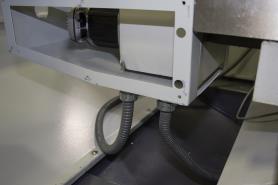
Put one flex conduit fitting on either end of the flex conduit as shown in the following image.
-
-
Connect one end of each flex conduit to the motor cover.
-
Find the servo power wires labeled 210 and 211 and the servo control wire labeled 424.
Tip! It may help to tape the ends of the cables together with electrical tape (or similar) before putting them through the flex conduit.
-
Route the wires through each flex conduit fitting on the motor cover. Verify that the Molex connectors are on the servo side of the flex conduit fittings.
-
Move the wires through the flex conduit fitting on the machine column and into the rear access compartment.
-
Tighten both flex conduits to their fittings on the machine column with Channellock pliers.
-
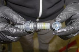
Find the dielectric grease provided with this kit. Then, put it on the Molex connectors of the servo power and control wires as shown in the following image.
-
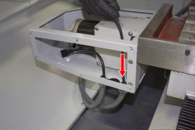
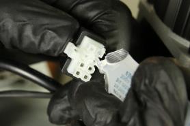
Make the servo wire connections at the motor as shown in the following image.
-
Put back the X-axis motor cover's plate with the six screws that you set aside in "Prepare the Machine for the X-Axis Motor Cover".
-
Find the three plastic plugs provided with this kit, and put them on the motor cover as shown in the following images.
NOTE: There may be extra plastic plugs provided with this kit.
-
To prevent coolant from entering the X-axis motor cover, you must first apply a layer of Sikaflex before putting back the tool tray. Clean the surfaces of the X-axis motor cover and the tool tray with a mild degreaser (like Simple Green®) to make sure that the Sikaflex bonds.
-
Find the tube of Sikaflex provided with this kit, and the tool tray that you set aside in "Prepare the Machine".
-
Put a bead of Sikaflex along the top edges of the X-axis motor cover.
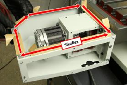
-
Put a bead of Sikaflex around the screw holes on the bottom of the tool tray.
-
Attach the tool tray to the X-axis motor mount with the screws that you set aside in "Prepare the Machine".
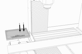
-
Verify that the tool tray is flush with the machine table: move a 1-2-3 block (or similar) across the two surfaces. Depending on the result, do one of the following:
-
Tool Tray is Flush with the Machine Table Go to Step 23.
-
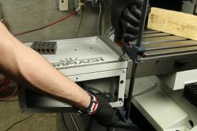
Tool Tray isn't Flush with the Machine Table Squeeze the tool tray down with a bar clamp until it's flush with the machine table, as shown in the following image. Then, tighten the screws.
-
-
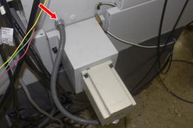
Find the two wires that you put into the machine column in the rear access compartment of the machine. Then, put the sleeves that you set aside in "Remove the Stepper Motor Drivers" (page 13) over them, and put the wires into the electrical cabinet.
Install the Z-Axis Servo Motor
-
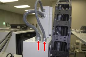
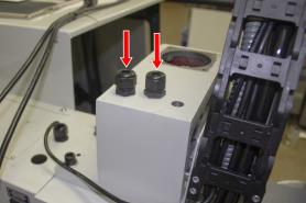
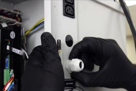
Find two cable glands provided with this kit.
-
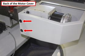
Install the two cable glands as shown in the following image.
-
Find the Z-axis brake. Then, install it on the machine column with the screws and washers that you set aside in "Remove the Stepper Motors".
-
Put the Z-axis brake’s wires through one of the cable glands on the machine column.
-
So that you can access it, align the Z-axis brake’s coupler and the hole on the brake with a 4 mm hex wrench.
-
Find the Z-Axis Servo Motor, 1100 (PN 38405). Then, install it in place of the motor that you removed in "Remove the Stepper Motors" with four M5 flat washers, M5 lock washers, and M5 × 0.8 - 20 mm screws provided with this kit.
-
Tighten the Z-axis brake coupler with a 4 mm hex wrench.
-
On the Z-axis motor coupler, tighten the two set screws closest to the motor with a 4 mm hex wrench.
-
Put back the Z-axis motor mount cover plate with the screws that you set aside in "Prepare the Machine".
-
Find the servo power wires labeled 230 and 231 and the servo control wire with label 426.
-
Put one wire through each of the cable glands. Verify that the Molex connectors are on the servo side of the cable glands.
Tip! It may help to tape the ends of the cables together with electrical tape (or similar) before putting them through the flex conduit.
-
Tighten the cable glands around the wires with Channellock pliers.
-
Find the dielectric grease provided with this kit. Then, put it on the Molex connectors of the servo power and control wires.
-
Make the servo wire connections at the motor.
-
Find the servo power wires, servo control wires, and Z-axis brake wires that you put into the machine column in the rear access compartment of the machine. Then, put the sleeves that you set aside in "Remove the Stepper Motor Drivers" over them, and put the wires into the electrical cabinet.
Install the Y-Axis Servo Motor
-
Find the Y-Axis Servo Motor, 1100 (PN 38701). Then, install it in place of the motor that you removed in "Remove the Stepper Motors" with the screws and washers that you set aside.
-
Tighten the two set screws on the coupler closest to the motor with a 4 mm hex wrench.
-
Put back the Y-axis motor mount cover with the screws that you set aside in "Prepare the Machine".
-
Early 1100M mills require different routing for the Y-axis motor. Depending on your machine's serial number, do one of the following:
MA10267 and Above Do the following:
a. Find two cable glands provided with this kit.
b. Install two cable glands in place of the Y-axis motor’s flex conduit fitting and the plug next to it, as shown in the following image.
c. Find the servo power wires labeled 220 and 221 and the servo control wire labeled 425.
d. Put one wire through each of the cable glands. Verify that the Molex connectors are on the servo side of the cable glands.
Tip! It may help to tape the ends of the cables together with electrical tape (or similar) before putting them through the flex conduit.
e. Tighten the cable glands around the wires with Channellock pliers.
f. Find the dielectric grease provided with this kit. Then, put it on the Molex connectors of the servo power and control wires.
g. Make the servo wire connections at the motor.
h. Find the two wires that you put into the machine column in the rear access compartment of the machine. Then, put them into the electrical cabinet.
MA10266 and Below Do the following:
a. Find one cable gland, one cord grip, and one cord grip nut.
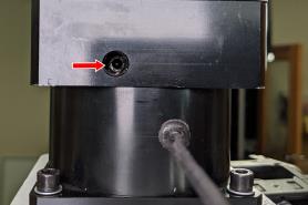
b. Install the cable gland in place of the Y-axis motor's flex conduit fitting.
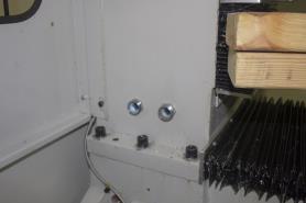
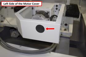
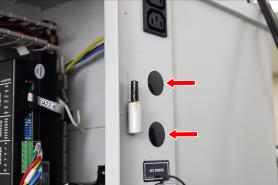
c. Identify the knockout holes on the machine column as shown in the following image. You'll use one of them to route the servo wires into the electrical cabinet.
d. From inside the electrical cabinet, push out the plug on either of the knockout holes. Discard the plug.
e. Secure the cord grip to the knockout hole on the machine column with the cord grip nut.
f. Find the servo power wires labeled 220 and 221 and the servo control wire labeled 425.
g. Put the wires into the electrical cabinet:
i. Put the servo control wire (425) through the cord grip.
ii. Put the servo power wires (220 and 221) through the cable gland.
Tip! It may help to tape the ends of the cables together with electrical tape (or similar) before putting them through the flex conduit.
Verify that the Molex connectors are on the servo side of the cable gland and cord grip.
h. Tighten the cable gland and the cord grip with Channellock pliers.
i. Find the dielectric grease provided with this kit. Then, put it on the Molex connectors of the servo power and control wires. Make the servo wire connections at the motor. Find the servo power wire that you put into the machine column in the rear access compartment of the machine. Then, put the sleeve that you set aside in "Remove the Stepper Motor Drivers" over it, and put the wire into the electrical cabinet.
Make Electrical Connections
-
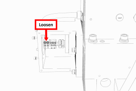
Remove the four Phillips head screws securing the protective cover to the machine control board with a Phillips screwdriver. Then, set aside the screws and the cover.
-
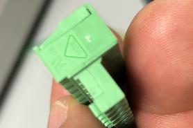
Find the three green connectors provided with this kit.
-
Identify the pin connection locations on the green connectors. Pin 1 is closest to the small triangle on the outside edge of the connector, as shown in the following image. Pins 2 through 8 follow in sequential order.
-
Find the three servo control cables that you put into the electrical cabinet in "Install the Servo Motors".
-
Connect each wire on the control cable to one of the green connectors as detailed in the following table.
|
Wire Number |
Wire Color |
Pin Connection |
|
X-Axis |
||
|
J13.1 |
Green |
1 |
|
J13.2 |
Black |
2 |
|
J13.3 |
White |
3 |
|
J13.4 |
Blue |
4 |
|
J13.5 |
Red |
5 |
|
J13.6 |
Yellow |
6 |
|
J13.7 |
Brown |
7 |
|
J13.8 |
Orange |
8 |
|
Y-Axis |
||
|
J14.1 |
Green |
1 |
|
J14.2 |
Black |
2 |
|
J14.3 |
White |
3 |
|
J14.4 |
Blue |
4 |
|
J14.5 |
Red |
5 |
|
J14.6 |
Yellow |
6 |
|
J14.7 |
Brown |
7 |
|
J14.8 |
Orange |
8 |
|
Z-Axis |
||
|
J15.1 |
Green |
1 |
|
J15.2 |
Black |
2 |
|
J15.3 |
White |
3 |
|
J15.4 |
Blue |
4 |
|
J15.5 |
Red |
5 |
|
J15.6 |
Yellow |
6 |
|
J15.7 |
Brown |
7 |
|
J15.8 |
Orange |
8 |
-
Route the control cables through the wire troughs and toward the machine control board.
-
Connect the green connectors to the machine control board as detailed in the following table.
|
Wire Number |
Connection |
|
424 |
J13 |
|
425 |
J14 |
|
426 |
J15 |
NOTE: The connection numbers are printed on the machine control board.
-
Route the Z-axis brake wires through the wire troughs, and then connect them in place of the original Z-axis brake wires.
NOTE: You recorded the locations of the original Z-axis brake wires in "Remove the Stepper Motor Drivers".
-
Find the three servo power cables that you put into the electrical cabinet in "Install the Servo Motors".
-
Find the six spade electrical connectors provided with this kit.
-
Remove 1/4 in. of insulation from each of the wires on the power cables. Then, crimp one spade electrical connector to each of the wires with a wire crimper.
-
Route the power cables through the wire troughs and toward the DC-BUS board.
-
Connect the spade connectors on the power wires to the DC-BUS board as detailed in the following table.
|
Wire Number |
Connection |
|
X-Axis |
|
|
210 |
X- |
|
211 |
X+ |
|
Y-Axis |
|
|
220 |
Y- |
|
221 |
Y+ |
|
Z-Axis |
|
|
230 |
Z- |
|
231 |
Z+ |
-
Organize the wires into the wire troughs, and then put any excess wire into the machine column.
-
Put back the wire trough covers.
-
Put the protective cover back on the machine control board using the screws that you set aside earlier.
-
Close the electrical cabinet door.
Verify the Installation
-
Put back the Z column cover that you set aside in "Prepare the Machine".
-
Power on the machine and the PathPilot controller.
-
Insert the power plug(s) into the wall outlet. If your system is hardwired, restore power to the circuit breaker(s).
-
Turn the Main Disconnect switch to ON on the side of the electrical cabinet.
-
Twist out the machine's red Emergency Stop button, which enables movement to the machine axes and the spindle.
-
Press the Reset button.
-
-
If you haven't yet done so, configure the PathPilot operating system for an servo motor mill configuration:
-
From the Main tab, in the MDI Line DRO field, type ADMIN CONFIG. Then select the Enter key.
-
From the Tormach Machine Controller Configuration screen, select the new machine configuration. Then select Save and Exit.
The PathPilot interface displays.
-
-
From the PathPilot interface, select Reset.
-
Confirm that the machine can freely move to the reference position:
-
Reference the Z-axis before referencing the other axes so that the spindle is clear of any possible obstructions: from the PathPilot interface, select Ref Z.
-
Once the spindle is clear of any possible obstructions, select Ref X and Ref Y.
-
-
Depending on the result of Step 5, do one of the following:
-
Correct Movement Remove the set of two-by-fours on the machine table, and put back the drip tray that you set aside in "Prepare the Machine".
-
Incorrect Movement We can help. Create a support ticket with Tormach Technical Support at tormach.com/how-to-submit-a-support-ticket for guidance on how to proceed.
-
Apply the 1100M+ Decals
We recommend using a wet application procedure to put the decals on your machine. It's easier to do (you can adjust as you work) and it creates a more professional appearance (you can easily push out air bubbles) – but it takes time to dry. Wait to use the machine until the decals dry completely so that you don't risk swarf (or other debris) moving the decals out of position.
To apply the 1100M+ decals:
-
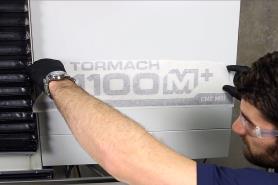
Remove the original 1100M decals on your machine. There's one on the front of the electrical cabinet, and one on the front left panel of the enclosure.
-
Find the enclosure and electrical cabinet decals provided with this kit.
-
Clean the surface of the removed decals with a mild degreaser (like Simple Green®). Then, let the surface dry.
-
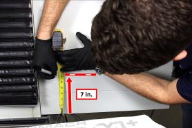
Identify the location for the new electrical cabinet decal: measure 7 in. from the bottom of the electrical cabinet, and make a mark. This indicates the correct location for the bottom of the new electrical cabinet decal. Repeat this step several times to help you align the new decal.
-
Identify the location for the new enclosure decal: measure 5.79 in. from both sides of the electrical cabinet, and make a mark on either side. This indicates the correct location for the sides of the new enclosure decal. Repeat this step several times to help you align the new decal.
-
Spray the application area with an ammonia-free window cleaner (or similar). The amount of window cleaner that you use determines how much flexibility you'll have to position the decal. If you use more window cleaner, it'll take longer to dry.
NOTE: You must use ammonia-free window cleaner to prevent air bubbles from forming.
-
Remove the protective backing from the decal.
-
Position the decals on the marks that you made in Step 4 and Step 5.
-
Push out all the air bubbles with a plastic squeegee (or similar).
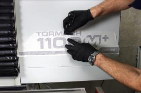
-
Carefully wipe the excess window cleaner off of the decal.
-
Allow up to a day for the decal to dry completely.
NOTE: Wait to use the machine until the decals dry completely so that you don't risk swarf (or other debris) moving the decals out of position.
-
Carefully remove the transfer paper from the decal.
To view a PDF version of your manual, go to Tormach document TD10580.
If you have additional questions, we can help. Create a support ticket with Tormach Technical Support at tormach.com/how-to-submit-a-support-ticket for guidance on how to proceed.