IMPORTANT! Please read this section before you begin installing your Automatic Tool Changer (ATC).
PathPilot You must update your controller to the latest version of PathPilot before installing and operating the ATC. If you don't, there's a risk that the ATC could become inoperable.
Purpose
This document gives instructions on installing and using an Automatic Tool Changer (ATC) for 1100M.
Product Information
Product: Automatic Tool Changer (ATC) for 1100M (PN 38400)
The Automatic Tool Changer (ATC) holds up to 12 tools in a single tray. If your program requires more tools, the ATC changes tools automatically for all tools assigned to the tray, and pauses for a manual tool change for all tools not assigned to the tray.
|
Quantity |
Description |
|
1 |
ATC Assembly |
|
3 |
ATC Fixed Standoff Assembly (PN 38492) |
|
10 |
Plastic Screw (PN 32173) |
|
1 |
ATC Tilt Adjust Eccentric Standoff Assembly (PN 38493) |
NOTE: If any items are missing, we can help. Create a support ticket with Tormach Technical Support at tormach.com/how-to-submit-a-support-ticket for guidance on how to proceed.
Before You Begin
-
If there's a tool holder in the spindle, remove it.
-
Remove any accessories or fixtures from the machine table.
-
Center the machine table: from the PathPilot interface, in the MDI Line DRO field, type G20 G53 G1 X9 Y-5.5 Z0 F20. Then select the Enter key.
IMPORTANT! You must update your controller to the latest version of PathPilot before installing and operating the Automatic Tool Changer. If you don't, there's a risk that the ATC could become inoperable. -
Update your controller: From the Status tab, select Update. Then, follow the on-screen instructions. Once the controller is updated to the latest version of PathPilot, go to Step 5.
WARNING! Electrical Shock Hazard: You must power off the machine before making any electrical connections. If you don't, there's a risk of electrocution or shock. -
Power off the machine and the PathPilot controller.
-
Push in the machine's red Emergency Stop button, which removes power to motion control.
-
From the PathPilot interface, select Exit.
-
Turn the Main Disconnect switch to OFF on the side of the electrical cabinet.
-
Setup
Required Tools
This procedure requires the following tools. Collect them before you begin.
Required Tools for Installation
-
1-1/2 in. adjustable wrench
-
Marker
-
Metric hex wrench set
-
Phillips screwdriver
-
Small, flat-head screwdriver
-
Snips
Required Tools for Verification
-
Machinist's square, between 6 in. and 9 in. (152 mm and 229 mm)
-
Straight rod (for tool holder), between 8 in. and 12 in. (203 mm and 305 mm)
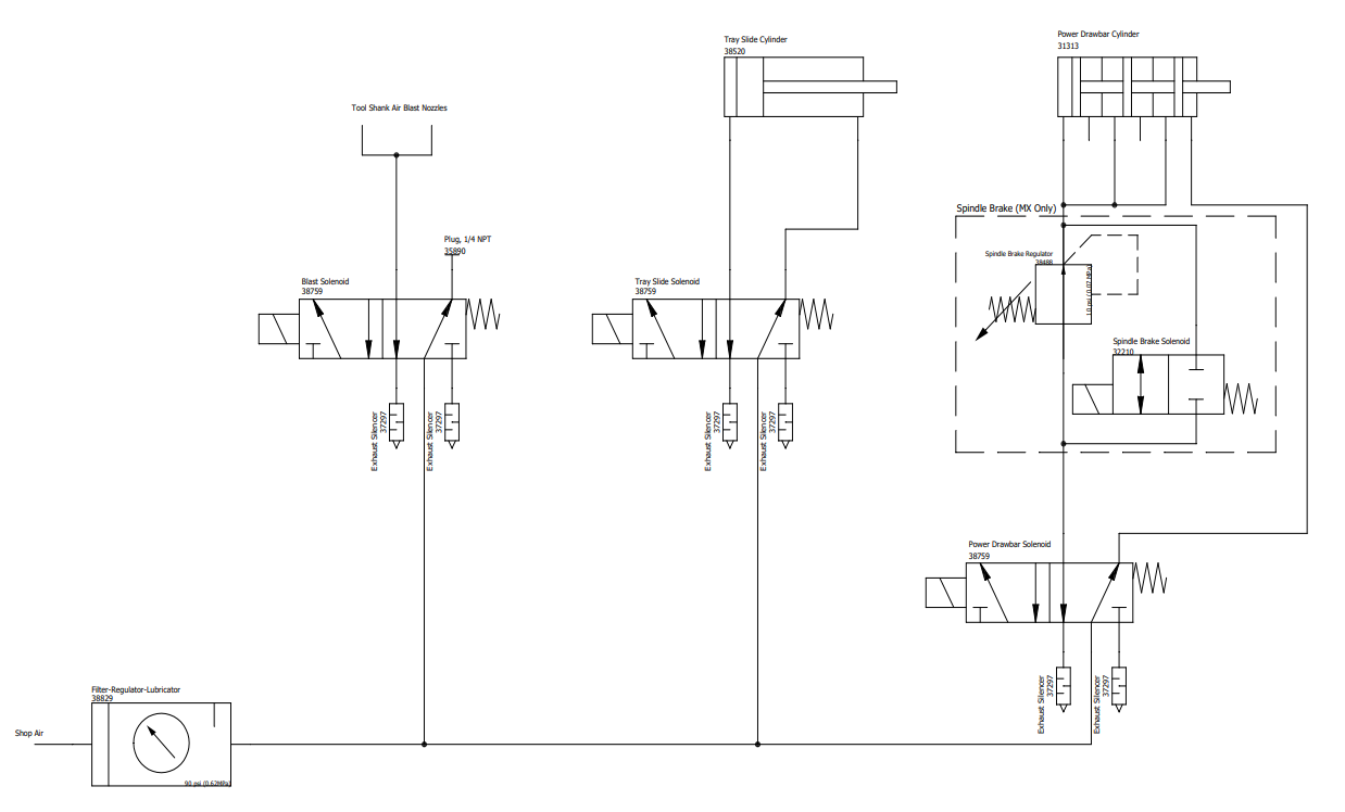
Air Requirements
You must verify that the site conforms to the following air supply requirements.
-
Air Pressure Between 90 psi and 120 psi (620 kPa to 825 kPa).
-
If the air supply is more than 120 psi (825 kPa), you must use a regulator.
-
Air Volume For successive back-to-back tool changes, at least 2 cfm at 90 psi is required.
-
Exact air volume depends on the frequency of tool changes.
-
Dry Air We recommend using a compressed air dryer, desiccator, or filter between the air compressor and the machine.
-
Lubricated Air You must lubricate the air with air tool oil.
Use the FRL Filter-Regulator-Lubricator (PN 32457) (included with the power drawbar kit) for this purpose.
Install the Automatic Tool Changer (ATC)
Complete the following steps in the order listed:
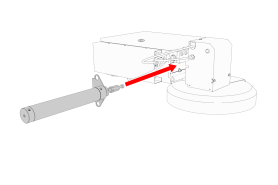
Disassemble the Power Drawbar Button
-
Disconnect the shop air supply from the machine.
-
Disconnect all air lines from the Power Drawbar button.
-
Remove four M5 × 0.8 - 10 mm button head cap screws that secure the Power Drawbar button cover.
-
Remove two M4 × 0.7 - 50 mm socket head cap screws that secure the Power Drawbar button to the spindle head.
-
Remove the Power Drawbar button from the spindle head.
Install the Air Cylinder
-
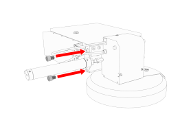
Attach the air cylinder on to the ATC main assembly.
-
Secure the air cylinder to the ATC main assembly with a 12 mm hex wrench (provided) and two M14 × 20 mm socket head cap screws.
-
Connect the air lines from the ATC main assembly to the air cylinder as follows:
-
Connect the short air line to the front of the cylinder.
-
Connect the long air line to the back of the cylinder.
-
Mount the Automatic Tool Changer (ATC) Bracket
-
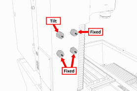
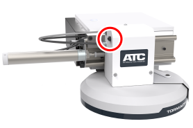
Identify the four provided standoffs that are used to mount the ATC to the Z-column:
-
Three fixed standoffs
-
One tilt standoff
-
-
Remove the flange nuts and the washers from the standoffs, and then set them aside.
-
Identify and remove the four set screws on the Z-column with a flat-blade screwdriver.
-
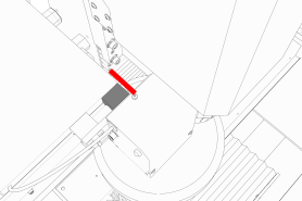
Install the four standoffs on the Z-column as shown in the following image.
-
Securely tighten the standoffs on the Z-column with a 1-1/2 in. adjustable wrench.
-
Put the ATC mounting bracket on the standoff's threaded studs as shown in the following image.
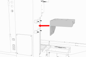
NOTE: Verify that the tilt standoff's eccentric cam fits into the large slot on the ATC mounting bracket.
-
Secure the bracket by reinstalling the washers and flange nuts that you removed in Step 2 with a 13 mm socket.
-
Pull the bracket toward the front of the machine. You'll make adjustments to the location of the bracket later in this procedure, but we recommend starting with it moved forward.
Install the Main Assembly
-
Remove the four preinstalled M8 × 1.25 - 16 mm socket head cap screws and washers from the bottom of the ATC electrical cabinet. Then, set all aside for later use.
CAUTION! Team Lift Required: You must have the aid of more than one person to lift and move the object. The object is heavy, and lifting it by yourself can cause serious injury. -
Lift the ATC main assembly on to the mounting bracket.
-
Align the locating pin on the ATC main assembly with the matching hole in the mounting bracket.
-
Secure the ATC main assembly to the mounting bracket with the four M8 × 1.25 - 16 mm socket head cap screws and washers that you set aside in Step 1.
Level the Automatic Tool Changer (ATC)
This section gives instructions to roughly level the ATC on the machine by using a long, straight rod. More adjustments are made later in the installation procedure.
NOTICE! After the initial installation, you must level the ATC. If you don't, there's a risk of machine damage.
Complete the following steps in the order listed:
Prepare the Machine
-
Push the tool tray toward the spindle.
-
Verify that the linear bearing on the ATC is flush with the ATC main assembly.
-
Find a straight rod between 8 in. and 12 in. (203 mm and 305 mm) long. Verify that it's straight: roll it on a known flat surface (like a granite surface plate).
NOTE: You'll use the rod to verify that the ATC is correctly installed on the mill, so it must be straight. -
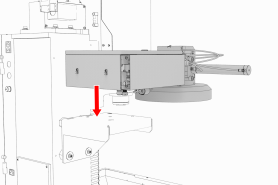
Put the alignment rod into a tool holder.
-
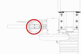
Put the tool holder into the fork so that the groove in the tool holder slides into the fork. Don't rest the tool holder on top of the fork.
-
Put a machinist's square on the machine table.
Examine Perpendicularity in the Y Direction
-
Verify that the rod is perpendicular to the machine table in the Y direction: compare the rod's position to the vertical edge of the machinist's square.
-
If the rod is perpendicular to the vertical edge of the machinist's square, go to "Examine Perpendicularity in the X Direction".
-
If the rod must be adjusted, go to Step 2.
-
-
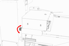
Loosen the flange nuts on the standoffs.
-
Turn the tilt standoff with an adjustable wrench, and slowly pivot the ATC until the rod is perpendicular to the vertical edge of the machinist's square.
-
Tighten the flange nuts with a 13 mm socket.
-
Reexamine the alignment of the ATC in the Y direction. If the rod isn't perpendicular to the vertical edge of the machinist's square, repeat Steps 2 through 5.
Examine Perpendicularity in the X Direction
-
Verify that the rod is perpendicular to the machine table in the X direction: compare the rod's position to the vertical edge of the machinist's square.
-
If the rod is perpendicular to the vertical edge of the machinist's square, go to "Examine the Alignment of the Carousel Door Opening".
-
If the rod must be adjusted, go to Step 2.
-
-
Loosen the two socket head cap screws on the linear rails.
-
Slowly pivot the linear rails up or down until the rod is perpendicular to the vertical edge of the machinist's square.
-
Tighten the socket head cap screws.
-
Reexamine the alignment of the ATC in the X direction. If the rod isn't perpendicular to the vertical edge of the machinist's square, repeat Steps 2 through 5.
Examine the Alignment of the Carousel Door Opening
-
Remove the tool holder from the fork, and set it aside.
NOTE: You'll need this tool later in the installation procedure to make further alignments. -
Power on the machine and the PathPilot controller.
-
Turn the Main Disconnect switch to ON on the side of the electrical cabinet.
-
Twist out the machine's red Emergency Stop button, which enables movement to the machine axes and the spindle.
-
Press the Reset button.
-
Bring the machine out of reset and reference it.
-
-
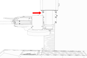
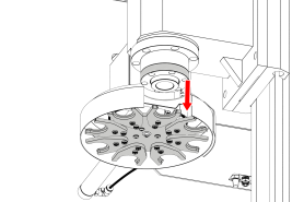
Verify that the ATC is all the way forward (toward the spindle), and then slowly move the Z-axis down (-Z) to examine the clearance of the carousel door opening.
-
Verify that the carousel door opening is approximately equal to the front back and left of the spindle mounting flange:
-
If the carousel door opening is approximately equal, go to Step 8.
-
b. If the carousel door opening must be adjusted, go to Step 5.
-
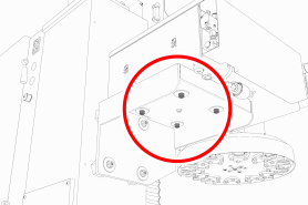
Loosen the four socket head cap screws that secure the ATC main assembly to the mounting bracket with a 6 mm hex wrench.
-
Adjust the carousel door opening as required:
-
If the Carousel Door Opening is Contacting the Front Pivot the ATC around the locating pin on the bottom of the mounting bracket toward the front of the machine (closer to you).
-
If the Carousel Door Opening is Contacting the Back Pivot the ATC around the locating pin on the bottom of the mounting bracket toward the back of the machine (closer to the machine column).
-
If the Carousel Door Opening is Contacting the Left Loosen the four flange nuts that attach the mounting bracket to the column to move the bracket forward or backward.
NOTE: Moving the ATC mounting bracket could change the position of the tilt standoff (on the Z-column). If you move it, you must verify that the ATC is still correctly installed; go to "Examine Perpendicularity in the Y Direction".
Repeat this step as needed.
-
-
Tighten the socket head cap screws and the flange nuts (if you loosened them in Step 5).
-
Move the tool tray to its retracted position.
-
Center the machine table: from the PathPilot interface, in the MDI Line DRO field, type G20 G53 G1 X9 Y-5.5 Z0 F20. Then select the Enter key.
-
Power off the machine and the PathPilot controller.
-
Push in the machine's red Emergency Stop button, which removes power to motion control.
-
From the PathPilot interface, select Exit.
-
Turn the Main Disconnect switch to OFF on the side of the electrical cabinet.
-
Make Air Connections
-
Cut the cable tie that secures the ATC cables and plastic tubes together with snips.
-
Route the loose ends of the two 1/4 in. plastic tubes connected to the ATC main assembly through the enclosure knockout, up the energy chain, and toward the Power Drawbar.
WARNING! Crush Hazard: If the ATC isn't completely retracted, it could move once the air is reconnected. When you reconnect the air, you must keep your hands away from the ATC. -
Trim and connect the loose ends of the 1/4 in. plastic tubes in the following order:
-
Connect the Retract (PDB Bottom) airline to the bottom push-to-connect elbow on the Power Drawbar.
-
Connect the Advance (PDB Top) airline to the top push-to-connect elbow on the Power Drawbar
-
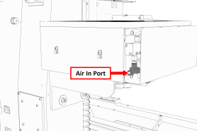
Connect the air supply line from the FRL to the air in port in the ATC main assembly, as shown in the following image.
-
d. If you haven't already done so, connect your shop's air supply to the FRL.
Make Electrical Connections
-
Route the ATC power cable and the USB cable toward the rear of the machine and out of one of the enclosure knockouts.
-
Put the USB cable in the access hole in the rear of the stand toward the controller.
-
Put the USB cable into an open USB port on the PathPilot controller.
IMPORTANT! Do not connect the ATC USB cable to a USB hub. Make the connection directly to the PathPilot controller itself. If you don't have any free USB ports on the controller, connect a different accessory to a USB hub. -
Connect the ATC power cable to the ATC Power connector on the side of the electrical cabinet (below the Enclosure Lights Power connectors).
Verify the Installation
-
Power on the machine and the PathPilot controller.
-
Turn the Main Disconnect switch to ON on the side of the electrical cabinet.
-
Twist out the machine's red Emergency Stop button, which enables movement to the machine axes and the spindle.
-
Press the Reset button.
-
Bring the machine out of reset and reference it.
IMPORTANT! You must update your controller to the latest version of PathPilot before operating the Automatic Tool Changer. If you don't, there's a risk that the ATC could become inoperable.
-
-
If you have not yet done so, you must make sure that the PathPilot controller is updated to the latest version of PathPilot: From the Status tab, select Update. Then, follow the on-screen instructions.
-
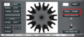
From the PathPilot interface, on the Settings tab, select the ATC radio button.
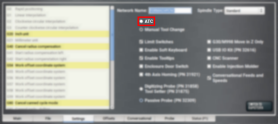
The ATC tab appears in the PathPilot interface.
NOTE: If prompted, you may need to update the firmware for the ATC. Follow the on-screen instructions.
-
Load a tool into the spindle:
-
Push and hold the collet open button on the side of the ATC.
-

The collet opens.
b. Load a tool into the spindle.
c. Release the button.
The collet closes.
-
From the PathPilot interface, on the Main tab, in the RPM DRO field, type 1000. Then select the Enter key.
-
Select FWD.
The spindle starts. -
From the Status tab, make sure that the VFD Running green light comes on.
NOTE: If the VFD Running light did not come on in the previous step, we can help. Create a support ticket with Tormach Technical Support at tormach.com/how-to-submit-a-support-ticket for guidance on how to proceed.
-
Select Stop.
The spindle stops.
Adjust the Power Drawbar
If you have not yet done so, you must adjust the Power Drawbar. Complete the following steps in the order listed:
Adjust the Drawbar Tension
This adjustment sets the highest possible drawbar tension while still allowing the Power Drawbar cylinder to release the tool.
NOTICE! After the initial installation, you must examine the drawbar tension weekly. During periods of heavy use, examine the drawbar tension more frequently. If you don't, there's a risk of tool pull-out.
To adjust the drawbar tension:
-
Put an empty Tormach Tooling System (TTS) tool holder into the collet.
-
While using one hand to support the tool holder, use the other to push the Release Tool button.
-
Depending on whether the tool holder releases or not, do one of the following:
-
If the Tool Holder Releases Tighten the Power Drawbar in quarter-turn increments with two adjustable wrenches. After each turn, push the Release Tool button. Stop when the tool holder does not release. Then, loosen the Power Drawbar one quarter-turn with two adjustable wrenches.
-
If the Tool Holder Doesn't Release Loosen the Power Drawbar in quarter-turn increments with two adjustable wrenches while pushing the Release Tool button. Stop when the tool holder releases.
-
Make a visual reference to help you set or adjust the drawbar tension in the future: use a paint pen to make a witness mark on both the head of the drawbar and the end of the spindle.
About Drawbar Tension
While machining, the Tormach Tooling System (TTS) collet holds a Tormach Tooling System (TTS) tool holder in the spindle by applying a clamping force to both the shank and the shoulder of the tool. The tension force that is applied to the drawbar pulls the Tormach Tooling System (TTS) collet into the spindle taper, which then applies the clamping force to the Tormach Tooling System (TTS) tool.
The force on the drawbar — known as drawbar tension — is applied differently depending on the tool changing method:
-
Automatic (using the Power Drawbar) Tension is applied by the compressed spring washers.
-
Manual Tension is applied when you tighten the drawbar into the collet using a wrench.
Adjust the Initial Setup
In this adjustment, you'll verify that there's enough clearance between the end of the drawbar and the Power Drawbar cylinder.
NOTICE! If you don't do this adjustment, there's a risk that the drawbar can loosen, or that operations can be louder than normal.
-
Examine the space between the hex head screw on the Power Drawbar cylinder's rod and the top of the drawbar.
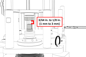
-
Verify that the gap is between 3/64 in. and 1/8 in. (1 mm and 3 mm). Depending on the size of the gap, do one of the following:
-
Between 3/64 in. and 1/8 in. (1 mm and 3 mm) You have completed adjusting the initial setup. Go to Operation.
-
Less Than 3/64 in. (1 mm) Go to Step 3.
-
-
Disconnect the shop's air supply from the Power Drawbar button.
-
Pull out the quick-release pin.
-
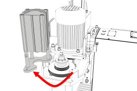
Pivot the Power Drawbar cylinder assembly to the left so that you can access the Power Drawbar cylinder's rod.
-
Remove the hex head screw on the Power Drawbar cylinder’s rod with an adjustable wrench, and set it aside.
-
Remove the M16 washer from the Power Drawbar cylinder’s rod, and set it aside.
-
Put the hex head screw back in, and then tighten it completely with an adjustable wrench.
-
Pivot the Power Drawbar cylinder to the original location.
-
Push in the quick-release pin.
-
Reconnect the shop's air supply to the Power Drawbar button.
-
Examine the space between the hex head screw on the Power Drawbar cylinder’s rod and the top of the drawbar.
-
Verify that the gap is between 3/64 in. and 1/8 in. (1 mm and 3 mm). Depending on the size of the gap, do one of the following:
-
Between 3/64 in. and 1/8 in. (1 mm and 3 mm) You have completed adjusting the initial setup.
-
Less Than 1/8 in. (1 mm) Go to Step 14.
-
-
Find the three provided M14 flat washers.
-
Put one M14 flat washer under each mounting post on the Power Drawbar cylinder.
Make Final Alignments to the Automatic Tool Changer (ATC)
Complete the following steps in the order listed:
Adjust the Tool Tray Load Position
-
Verify that there’s no tool in the spindle.
-
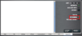
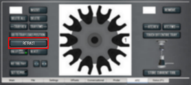
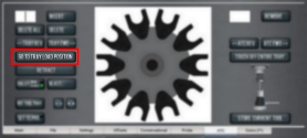
From the PathPilot interface, on the ATC tab, select Ref Tool Tray.
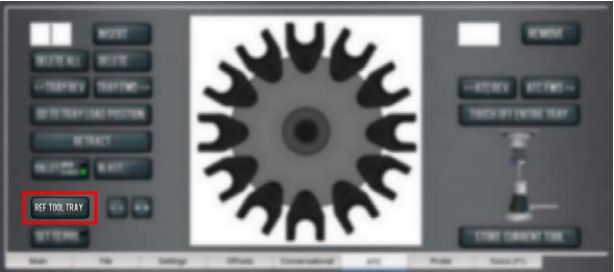
The tool tray spins.
NOTE: You’re only required to reference the tool tray once, unlike the mill axes' referencing procedure.
-
Select Go to Tray Load Position.
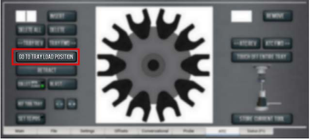
-
When prompted, select OK.
The tool tray moves forward. -
Put the tool holder with the rod into the fork.
-
From the PathPilot interface, slowly jog the Z-axis down (-Z) to bring the spindle nose toward the tool in the tool tray.
-
Make sure that the tool’s shank is aligned concentrically with the collet in the spindle.
-
If the tool's shank isn't aligned, do the following:
-
Adjust the Alignment of the Tool in the Y Direction (toward or away from the Z column) Determine if the tray must move clockwise or counterclockwise. From the PathPilot interface, in the ATC tab, either select -- to step the tool tray counterclockwise or ++ to step the tool tray clockwise.
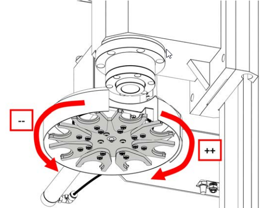
-
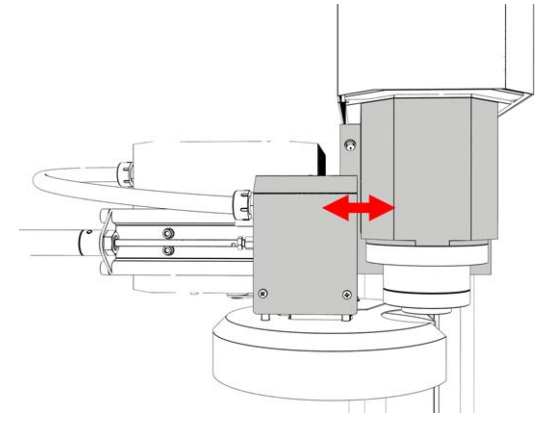
Adjust the Alignment of the Tool in the X Direction (left or right) Determine if the tray must move left or right. Use two wrenches to loosen the jam nut on the end of the cylinder rod, making sure that you don't spin the rod end when adjusting the jam nut. Then, either turn the rod end one-half turn further on to the cylinder rod to move the tool tray to the left, or turn it one-half turn off of the cylinder rod to move the tool tray to the right. Once finished, tighten the jam nut.
Repeat adjustments until the tool's shank is concentric with the collet in the spindle.
-
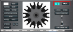
From the PathPilot interface, on the ATC tab, select Retract.
Verify the Alignment
-
From the PathPilot interface, select Go to Tray Load Position.
-
Slowly jog the Z-axis down (-Z) over the tool’s shank.
-
Verify that the tool’s shank moves freely into the collet.
-
Depending on the tool's shank movement, do one of the following:
-
Moves Freely Go to "Set the Tool Change Height".
-
Doesn't Move Freely This indicates that the ATC is misaligned and you must realign it. Go to "Adjust the Tool Tray Load Position".
Set the Tool Change Height
-
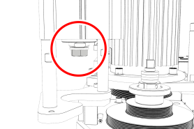
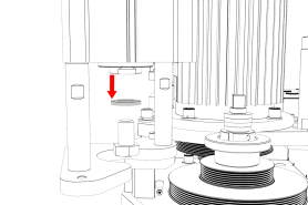
From the PathPilot interface, slowly jog the Z-axis down (-Z) over the tool. Stop jogging when the spindle nose just makes contact with the shoulder of the tool holder.
-
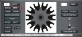
On the ATC tab, select Set TC POS.
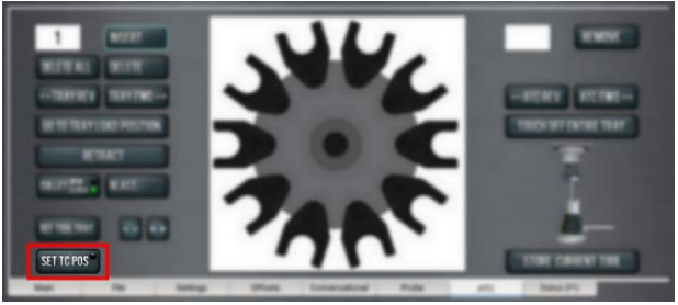
The tool change position is set.
Adjust for Rotational Play
There's a small amount of rotational play built into the Automatic Tool Changer (ATC) carousel. This play allows for some misalignment during tool changes, and you must adjust for it in both directions. The taper on the tool shank also helps align the tool during a tool change.
To adjust for rotational play:
-
From the PathPilot interface, on the ATC tab, select Tray Fwd to rotate the tray clockwise (forward) one full tool slot.
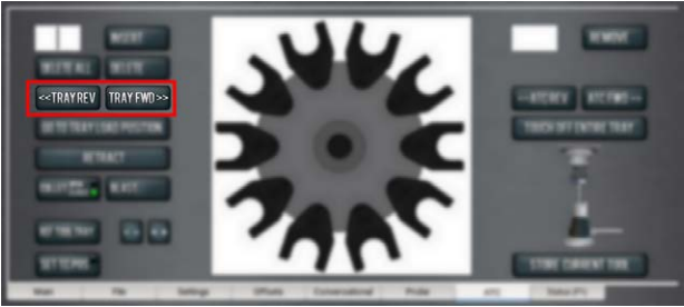
-
Select Tray Rev to rotate the tray counterclockwise (backward) one full tool slot.
-
Verify that the tool’s shank is aligned with the collet in the spindle.
-
Depending on the alignment, do one of the following:
-
Aligned You have completed aligning the ATC. Remove the tool from the fork. Go to Step 5.
-
Not Aligned You must readjust the tool tray rotation. Go to "Adjust the Tool Tray Load Position".
-
From the PathPilot interface, on the Main tab, drag the Maxvel Override slider to the left. This reduces the maximum velocity by the percentage shown.
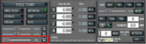
-
Do a test tool change. Because the maximum velocity is reduced, it's easier to verify the alignment of the ATC and stop the machine if further adjustment is required.
Tip! Use the Spacebar key to pause the tool change, if needed.
Operation
NOTE: You must always have a tool holder in the collet while the machine is not in use. Retracting the Power Drawbar to the clamped position with no tool holder in the collet will eventually fatigue the collet, and may shorten its service life. For more information, refer to the Power Drawbar documentation.
Read the following sections to understand how to operate the ATC:
Assign Tool Numbers
Use any tool number, from 1-1000, to assign a position in the tool tray.
Automatically Load a Tool into the Tool Tray
-
Load a tool into the spindle.
-
From the PathPilot interface, on the ATC tab, type the tool number in the Tool DRO field. Then select the Enter key.
-
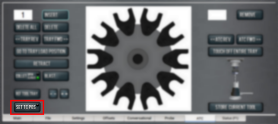
Select Store Current Tool.
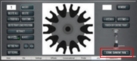
The tool is assigned to the nearest open slot. The ATC fetches the tool from the spindle and stores the tool in the tray. When stored, the tool number displays on the tray image in the center of the screen.
-
Click Retract.
The tray returns to the machining position.
Automatically Unload a Tool From the Tool Tray
NOTE: Typing a new tool number in the Tool DRO field doesn't remove the tool from its tray assignment.
-
From the PathPilot interface, on the ATC tab, type the tool number in the Remove DRO field. Then select the Enter key.
-
Select Remove.
The ATC fetches the tool from the tray. -
Unload the tool from the spindle.
-
From the ATC tab, select ATC FWD or ATC REV.
The tray moves to the next location and fetches another tool.
-
Select Retract.
The tray returns to the machining position.
Load a Tool into the Spindle
Load a tool into the spindle:
-
Push and hold the collet open button on the side of the ATC.
The collet opens.
-
Load a tool into the spindle.
-
Release the button.
The collet closes.
Manually Load a Tool Into the Tool Tray
-
From the PathPilot interface, on the ATC tab, select Go To Tray Load Position.
The spindle head moves up and the ATC moves into the door open position.
-
Load a tool into an open fork on the tray.
-
From the ATC tab, type the tool number into the Insert DRO field. Then select the Enter key.
-
Select Insert.
The tool is assigned to the exposed tray slot. -
Select Tray FWD or Tray REV.
The tray moves to the next slot location. -
Select Retract.
The tray returns to the machining position.
Manually Unload a Tool From the Tool Tray
-
From the PathPilot interface, on the ATC tab, in the Insert DRO field, type the tool number. Then select the Enter key.
-
Select Go To Tray Load Position.
The spindle head moves up and the ATC moves into the door open position. -
Select Delete.
The tool is unassigned from the tray and the tray moves to that tool.
-
Select Tray FWD or Tray REV.
The tray moves to the next slot location. -
Select Retract.
The tray returns to the machining position.
Retrieve a Tool From the Tool Tray
-
Depending on your workflow, do one of the following from the PathPilot interface:
-
Type the command directly into the MDI Line DRO field using the following format: T[TOOL NUMBER] M06
For example, T1 M06
-
-
Type the tool number in the Tool DRO field. Then select the Enter key.
Set the Tool Change Height
-
From the PathPilot interface, slowly jog the Z-axis down (-Z) over the tool. Stop jogging when the spindle nose just makes contact with the shoulder of the tool holder.
-
On the ATC tab, select Set TC POS.
The tool change position is set.
Switch to Manual Tool Changes
From the PathPilot interface, on the Settings tab, select the Manual Tool Change radio button.
The Automatic Tool Changer (ATC) is prevented from making tool changes.
Troubleshooting
If you're having issues with the ATC, read the following sections:
Lubricate the Linear Rails
The linear rails are self-lubricating, so you don't need to lubricate them. If, after initial installation, you hear chatter from the linear rails, apply a thin layer of way oil to the linear rails.
Replace the Plastic Screws on a Fork
The plastic screws that hold the fork to the tool tray are designed to fail under greater-than-normal loads: when a tool crashes, the plastic screws snap to prevent damage to the Automatic Tool Changer (ATC). If the plastic screws that hold the fork to the tool tray break, you can replace them.
To replace the plastic screws on a fork:
-
Remove the broken screws from the fork.
-
Secure the fork to the tool tray with two of the included plastic screws. Make sure that the groove on the fork faces the machine table.
NOTICE! Don't use metal screws to replace broken screws on an ATC fork. If you do, it could cause machine damage.
You must adjust the tool tray rotation again: go to Adjust the Tool Tray Load Position.
Schematics
To view a PDF version of your manual, go to Tormach document TD10426.
If you have additional questions, we can help. Create a support ticket with Tormach Technical Support at tormach.com/how-to-submit-a-support-ticket for guidance on how to proceed.