Purpose
This document gives instructions on installing the BT30 Spindle Upgrade Kit for 1100M+.
Product Information
Product: BT30 Spindle Upgrade Kit for 1100M+ (PN 50472)
|
Quantity |
Description |
|
1 |
9-Position Terminal Block (PN 32634) |
|
1 |
1100MX Spindle Belt (PN 50402) |
|
1 |
BT30 Spindle Cartridge Assembly, 1100MX (PN 39590) |
|
1 |
BT30 Clamping Unit Installation Tool (PN 50385)NOTE: Keep this item to use in the future if you need to replace the pull stud clamping unit. This item isn't used in this installation procedure. |
|
1 |
Cord Grip (PN 38758) |
|
3 |
Cable Tie (PN 32791) |
|
3 |
Cable Tie Holder (PN 33193) |
|
1 |
Magnetic Encoder, Readhead (PN 38299) |
|
1 |
Motor Pulley Spacer, 1100 (PN 30347) |
|
2 |
Screw, Button Head Cap (Flanged), M5 × 0.8 - 10, Stainless Steel (PN 38205) |
|
1 |
Spanner Wrench (38-42 mm) (PN 31038) |
NOTE: If any items are missing, we can help. Create a support ticket with Tormach Technical Support at tormach.com/how-to-submit-a-support-ticket for guidance on how to proceed.
Required Tools
This procedure requires the following tools. Collect them before you begin.
-
3 in. (7.6 cm) wooden block, 2
-
6 in. Gear puller
-
Flat-blade screwdriver
-
Metric hex wrench set
-
Open-ended wrenches:
-
13 mm
-
19 mm
-
25 mm
-
-
Phillips screwdriver
-
Safety eyewear
-
Simple Green (or similar mild degreaser)
-
Torque wrench
-
WD-40® (or similar water displacement oil)
Before You Begin
-
M+ Upgrade Required You must use servo motors with the BT30 spindle. If you haven't yet done so, install the 1100M+ Servo Upgrade Kit (PN 39274).
-
Power Drawbar Required You must have a power drawbar to use with the BT30 spindle. Depending on what's installed on your machine, do one of the following:
-
TTS Power Drawbar Installed Use the TTS to BT30 Power Drawbar Conversion Kit (PN 50474) to upgrade your existing power drawbar.
-
No Power Drawbar Installed Install the 1100MX/770MX Power Drawbar Kit (PN 50433).
-
-
Keep All Hardware To install the BT30 spindle, you'll reuse many items currently used on the machine. Keep all hardware unless you're specifically instructed to discard it. If you don't, there's a risk that you won't have the hardware you need to complete the installation.
-
PathPilot v2.4.2 or Later Required Only PathPilot v2.4.2 and later has settings required to use an MX mill configuration. For information, go to "Update PathPilot".
-
VFD Required Only for Machines MA10629 and Below Early M machines required a new VFD to complete the upgrade to an MX machine. All current machines (serial number MA10630 and above) do not require a new VFD.
Update PathPilot
Before you begin to install this kit, you must verify that the PathPilot controller is updated to the latest version of PathPilot. This is because only PathPilot v2.4.2 and later has settings required to use a BT30 spindle mill configuration.
To update PathPilot, do one of the following:
Download and Install an Update File from the Controller
-
Confirm that the PathPilot controller is powered on and out of Reset mode.
-
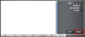
Downloading and installing an update file requires an Internet connection. From the Status tab, confirm that the Internet button LED light is on. (To configure the network, select the LED light.) Then, select Update.

-
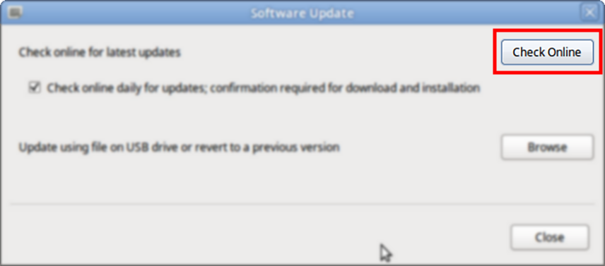
From the Software Update dialog box, select Check Online.
-
Select Install.
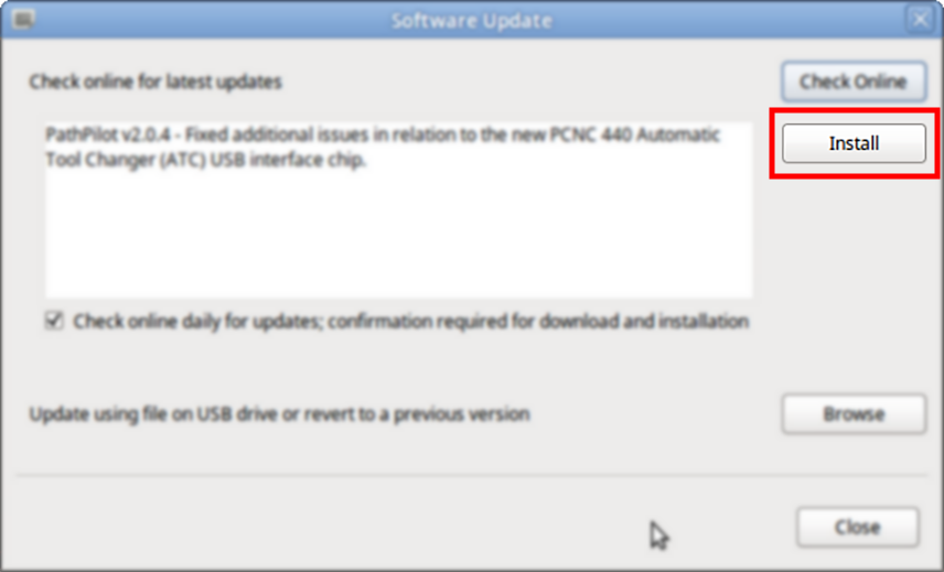
The update file is downloaded, and a notification dialog box displays.
-
From the dialog box, select OK.
The update file is installed on the PathPilot controller. -
Follow the on-screen instructions to restart the PathPilot controller.
Install an Update File from a USB Drive
-
From the PathPilot support center, download the most recent PathPilot update file.
-
Transfer the PathPilot update file to a USB drive.
-
Put the USB drive into the PathPilot controller.
-
Confirm that the PathPilot controller is powered on and out of Reset mode.
-
From the Status tab, select Update.
-
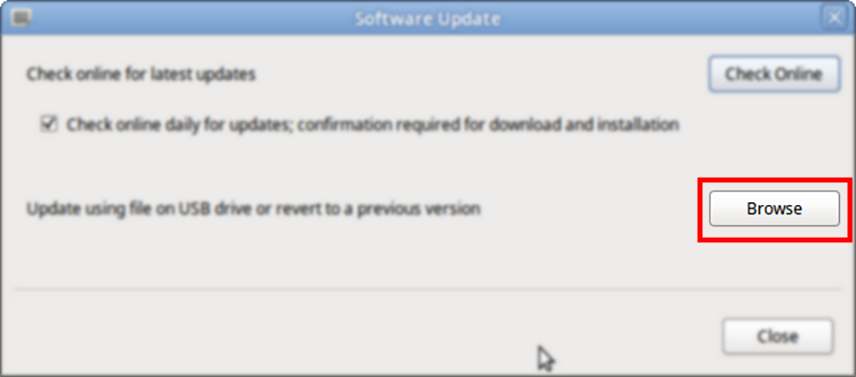
From the Software Update dialog box, select Browse.
-
From the Browse dialog box, select USB.
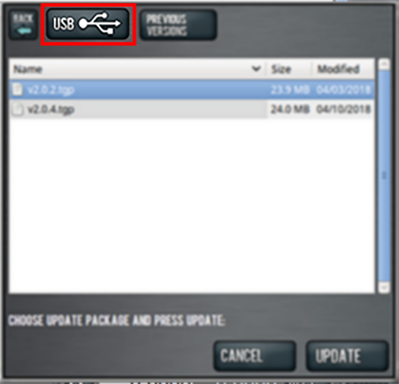
-
Select the desired update file, and then select Update.
The update file is installed on the PathPilot controller. -
Follow the on-screen instructions to restart the PathPilot controller.
Installation
Complete the following steps in the order listed:
Remove the R8 Spindle
Tip! For more information while removing original components of the machine, it may help to refer to the "Spindle Head" exploded view (in the Resources section of this document).
Prepare the Machine
-
Remove any tooling, fixtures, workpieces, or parts from the machine.
-
Jog the spindle nose until it's approximately 6 in. (15.2 cm) above the machine table.
-
Power off the machine and the PathPilot controller.
-
Push in the machine's red Emergency Stop button, which removes power to motion control.
-
From the PathPilot interface, select Exit.
-
Turn the Main Disconnect switch to OFF on the side of the electrical cabinet.
-
-
Disconnect any pneumatic air lines on the machine, and verify that the lines are empty.
-
Open the spindle cover and lock it in the up position.
-
Disconnect the spindle motor quick-connect fitting.
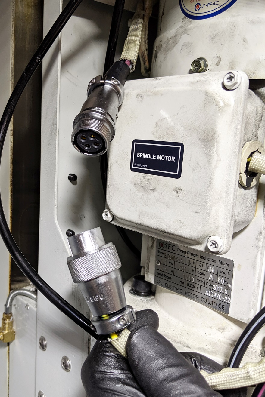
The procedure varies based on your tool changing method. Depending on what's installed on your machine, do one of the following:
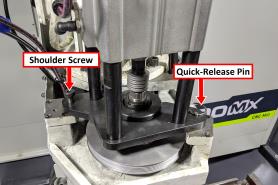
Remove the Power Drawbar
-
Confirm that the top air line is labeled Top, and the bottom air line is labeled Bottom. If the air lines aren't labeled, label them.
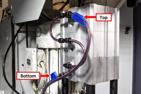
-
Disconnect the 1/4 in. air lines from the top and bottom push-to-connect fittings on the power drawbar cylinder.
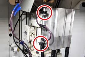
-
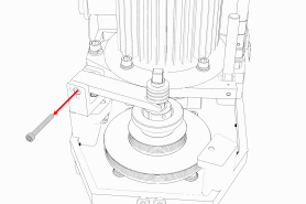
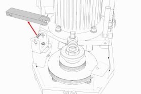
Use a 5 mm hex wrench to remove the shoulder screw from the base plate. Then, pull out the quick-release pin.
-
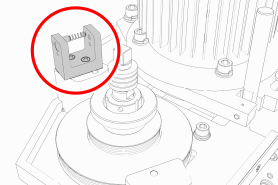
Remove the power drawbar cylinder.
-
Go to "Remove the R8 Spindle"
Disassemble the Original Drawbar
CAUTION! Loose Objects Hazard: The original drawbar contains spring-loaded hardware, which could quickly become loose, causing serious injury. Before disassembling the original drawbar, you must put on safety eyewear that meets ANSI Z87+.
-
Put on safety eyewear.
-
While using one hand to hold the spindle lock arm, use the other to remove the spindle lock arm pivot screw with a 5 mm hex wrench.
NOTE: The spindle lock arm assembly contains spring-loaded hardware, which could quickly become loose.
-
Carefully remove the spindle lock arm.
-
Remove the spindle lock base with a 5 mm hex wrench.
-
From the spindle door, remove the spindle lock arm with a 4 mm hex wrench.
-
Go to "Remove the R8 Spindle".
Remove the R8 Spindle
-
Remove the existing drawbar assembly (including its spring washers) and the R8 collet with a 13 mm and 19 mm open-ended wrench.
-
Release the tension from the spindle belt, and then remove it from the machine.
-
Loosen the three set screws on the pulley retention nut with a 3 mm hex wrench.
-
Remove the pulley retention nut from the machine with the spanner wrench (provided). The pulley retention nut secures the power drawbar flange, pulley, and pulley spacer, which are keyed to the spindle shaft.
Remove the power drawbar flange.
NOTE: You'll remove the spindle pulley later in this procedure.
-
Power on the machine and the PathPilot controller.
-
Turn the Main Disconnect switch to ON on the side of the electrical cabinet.
-
Twist out the machine's red Emergency Stop button, which enables movement to the machine axes and the spindle.
-
Press the Reset button.
-
Bring the machine out of reset and reference it.
-
-
Remove five of the socket head cap screws that secure the spindle flange to the head casting with a 6 mm hex wrench. Set them aside.
-
Loosen the remaining socket head cap screw.
CAUTION! The spindle secures to the head casting with six socket head cap screws on the bottom face of the spindle nose. Once you remove them, the spindle will begin to fall out of the casting. You must rest the spindle on a block of wood before removing the final socket head cap screw. If you don't, there's a risk of injury or machine damage.
-
Center the machine table: from the PathPilot interface, in the MDI Line DRO field, type G20 G53 G1 X9 Y-5.5 Z0 F20. Then select the Enter key.
The machine table moves to the center position. -
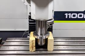
Put a 3 in. (7.6 cm) wooden block on the machine table below the spindle nose.
-
Slowly lower the spindle until the spindle nose is on the wooden block.
-
Remove the remaining socket head cap screw with a 6 mm hex wrench. Set it aside.
-
Slowly jog the Z-axis up (+Z) to raise the head casting until you have enough clearance to remove the spindle pulley.
NOTE: You may need to move the spindle pulley back-and-forth as the Z-axis moves up in order to remove it.
-
Continue to jog the Z-axis up (+Z) to raise the head casting until you can remove the spindle.
-
Discard the following items:
-
Drawbar
-
Power drawbar flange
-
R8 collet
-
Retention nut
-
Spindle
-
Spindle pulley
-
Install the BT30 Encoder
-
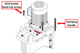
Remove the spindle motor's pivot plate clamping handle.
-
Remove the M10 socket head cap screw from the pivot bushing.
-
Remove the spindle motor and its pivot plate assembly from the spindle head.
Set the assembly aside. -
Slowly jog the Z-axis down (-Z) until the spindle motor housing is in a convenient location to work in.
-
Power off the machine and the PathPilot controller.
-
Push in the machine's red Emergency Stop button, which removes power to motion control.
-
From the PathPilot interface, select Exit.
-
Turn the Main Disconnect switch to OFF on the side of the electrical cabinet.
-
-
Clean the inside of the spindle motor housing with Simple Green (or similar mild degreaser).
-
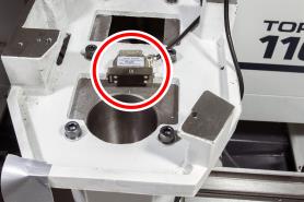
Find the encoder read head and its two button head cap screws provided in this kit.
-
Install the encoder read head on the head casting with the button head cap screws using a 3 mm hex wrench. Leave the encoder just loose enough to make final adjustments later in this procedure.
-
Route the wire from the encoder along the floor of the casting, up behind the spindle door switch, and up through the energy chain.
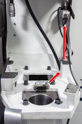
Tip! We recommend using a piece of heavy-gauge wire as a pull to route the encoder wire through the energy chain.
-
Identify surfaces on which to secure the encoder wire to the machine with the provided cable ties and cable tie holders. Then, clean the surfaces where you'll put the cable tie holders.
-
Put all three cable tie holders in the locations that you just cleaned.
-
While holding one of the cable tie mounts, secure the encoder wire with one cable tie. Repeat for all cable tie holders. Once finished, verify that the encoder wire won't become entangled or damaged.
-
Identify the knockout holes on the top of the electrical cabinet. Remove one, and put one provided cord grip in its place.
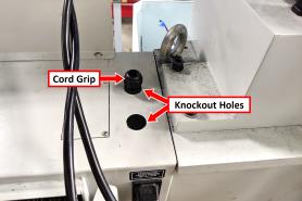
-
Find the encoder wire that you routed through the energy chain. Then, route the wire through the cord grip and into the electrical cabinet.
-
Open the electrical cabinet door.
-
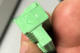
Find the 9-position terminal block provided in this kit.
-
Identify the pin connection locations on the terminal block. Pin 1 is closest to the small triangle on the outside edge of the connector, as shown in the following image. Pins 2 through 8 follow in sequential order.
-
Find the encoder wire that you routed through the cord grip into the electrical cabinet. Then, connect each encoder wire to the terminal block as detailed in the following table.
|
Connector Terminal Number |
Encoder Wire Color |
|
J9.1 |
Red |
|
J9.2 |
Green |
|
J9.3 |
Brown |
|
J9.4 |
White |
|
J9.5 |
Gray |
|
J9.6 |
Yellow |
|
J9.7 |
Orange |
|
J9.8 |
Black |
|
J9.9 |
No Connection |
-
Inside the electrical cabinet, remove the top wire trough cover and set it aside.
-
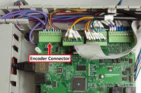
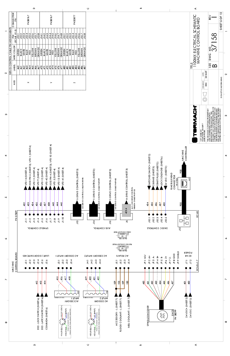
On the ECM v1.5 board, identify the J9 connector. For information, see "Machine Control Board”.
-
If necessary, remove any tabs from the wire troughs surrounding the connector so that you can easily make wire connections.
-
Connect the terminal block with the encoder wires to J9 on the ECM v1.5 board.
-
Organize the wires into the wire troughs.
-
Put back the top wire trough cover.
-
Install the motor and its pivot plate assembly back onto the machine.
Replace the Spindle Motor Pulley Spacer
-
Find the motor pulley spacer provided with this kit.
-
Replace the original spindle motor pulley with the two-stage pulley:
-
Use a 6 mm wrench to remove the M8 socket head cap screw and washer securing the motor pulley to the motor shaft.
-
Remove the spindle motor pulley from the motor shaft with a gear puller.
-
Tip! If you find it difficult to remove the spindle motor pulley with a gear puller, we recommend carefully using two thin pry bars.
c. Remove the shaft key and set it aside.
d. Remove the motor pulley spacer from the motor shaft. Discard the motor pulley spacer.
e. Put the motor pulley spacer (provided) into the motor shaft.
NOTE: The provided motor pulley spacer is thicker than the original.
f. Replace the shaft key that you set aside in Step C.
g. Secure the motor pulley with the socket head cap screw and washer that you removed in Step A.
-
Install the motor and its pivot plate assembly back onto the machine.
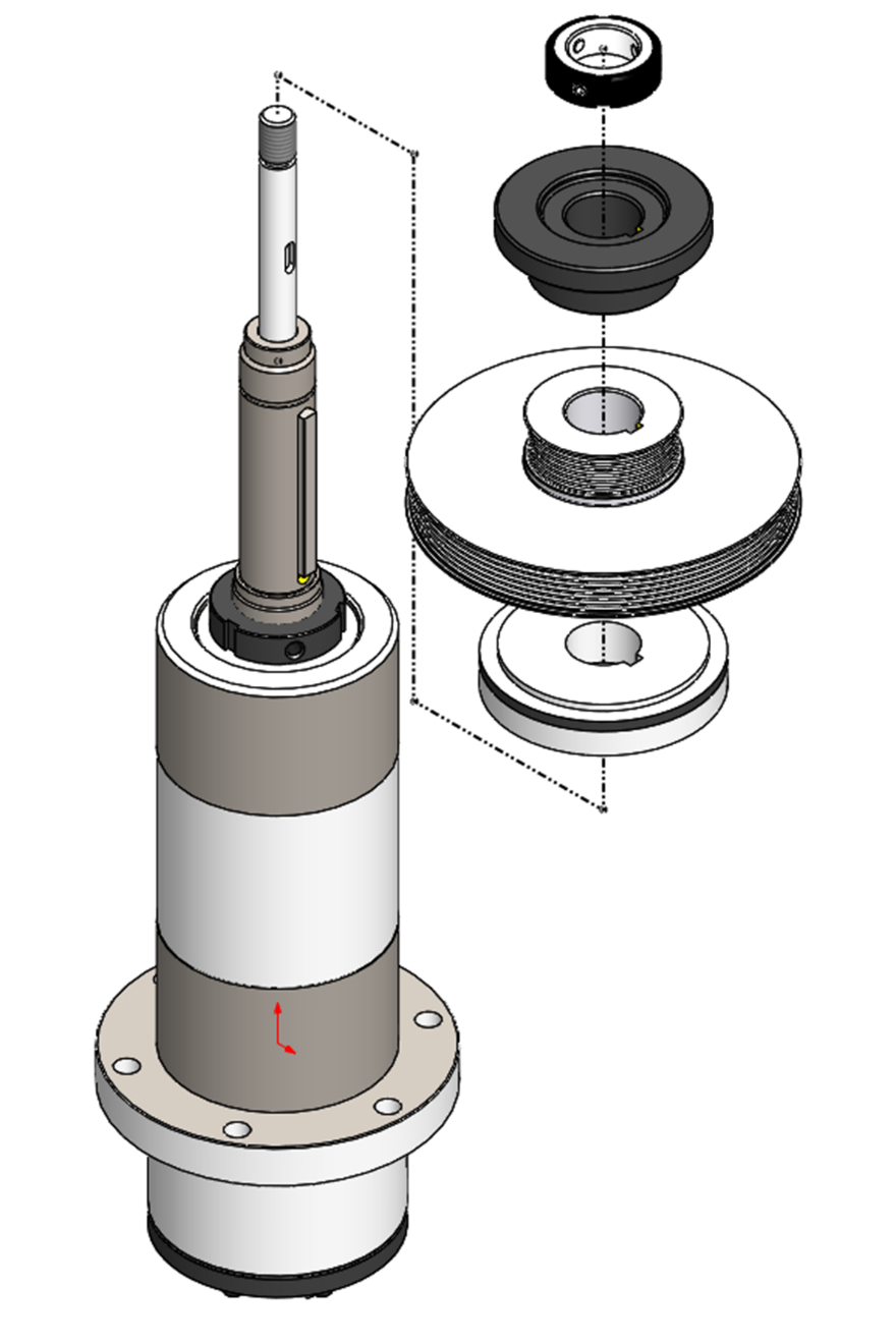
Install the BT30 Spindle and Align the Encoder
Tip! For more information while installing BT30 components on the machine, it may help to refer to the "Spindle Cartridge".
-
Power on the machine and the PathPilot controller.
-
Turn the Main Disconnect switch to ON on the side of the electrical cabinet.
-
Twist out the machine's red Emergency Stop button, which enables movement to the machine axes and the spindle.
-
Press the Reset button.
-
Bring the machine out of reset and reference it.
-
-
Find the BT30 spindle provided in this kit.
-
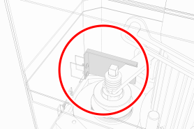
Disassemble the BT30 spindle:
-
Use a 4 mm hex wrench to prevent rotation of the drawbar shaft.
-
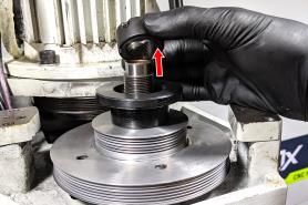
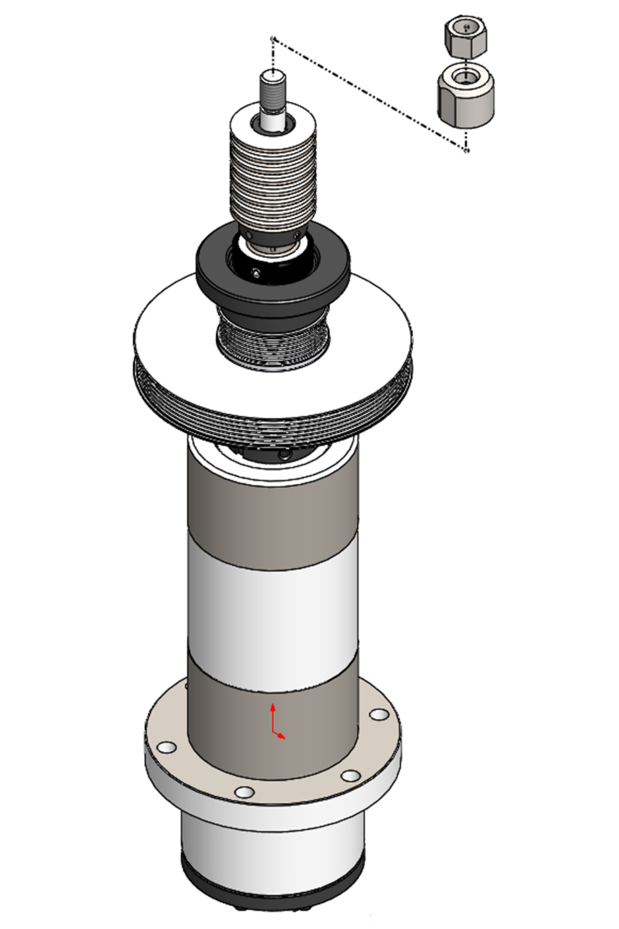
b. From the top of the drawbar, remove the jam nut with a 19 mm open-ended wrench and remove the disc spring compression nut with a 25 mm open-ended wrench. Some drawbar assemblies also include a number of shim washers beneath the disc spring compression nut. If your spindle includes these, save them and reinstall them in the same location in Step 22.
c. Loosen the two set screws on the disc spring guide with a 2 mm hex wrench, and then remove the following items from the drawbar stack assembly:
-
Disc springs, 16
-
Disc spring guide
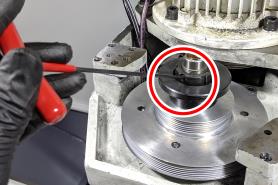
d. Loosen the three set screws that secure the retention nut with a 3 mm hex wrench.
e. Remove the retention nut with the provided spanner wrench. Set the retention nut aside.
Tip! For a better grip on the pulley, we recommend using the old 260 Poly-V belt to hold it in place.
f. Remove the following items from the BT30 spindle:
-
Encoder ring
-
Power drawbar flange
-
Pulley
Then, set all items aside.
-
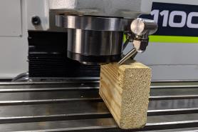
Put two 3 in. (7.6 cm) blocks of wood on the machine table on either side of the spindle hole.
-
Put a thin coating of WD-40® (or similar water displacement oil) on the outside of the spindle.
-
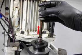
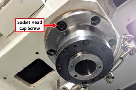
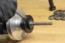
Identify the hole on the spindle flange as shown in the following image.
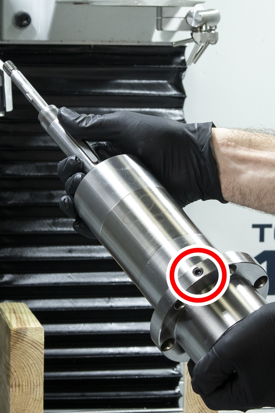
-
Turn the spindle so that the hole is pointing toward the machine column. Then, put the spindle between the two blocks of wood on the machine table.
-
Slowly jog the Z-axis down (-Z) until the head casting is flush with the spindle flange.
-
Find the six socket head cap screws that you set aside in "Remove the R8 Spindle" (page 9). Secure the spindle flange to the head casting with one of the socket head cap screws.
-
Slowly jog the Z-axis up (+Z) until you can remove the two blocks of wood from the machine table.
-
Install the five remaining socket head cap screws into the spindle flange.
-
Working in a star pattern, tighten all six socket head cap screws to 20 ft lbs.
-
Install the encoder ring with the magnetic ring pointing up (away from the machine table). Then, remove any stickers from the encoder ring.
-
Position the encoder tangent to the encoder ring, setting the distance using a piece of paper (approximately 0.003 in.).
-
Tighten the two flange screws to secure the encoder in place. Remove the shim.
-
Rotate the spindle by hand to confirm that there's no risk of entanglement.
-
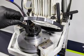
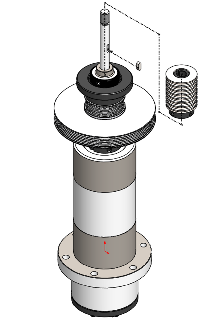
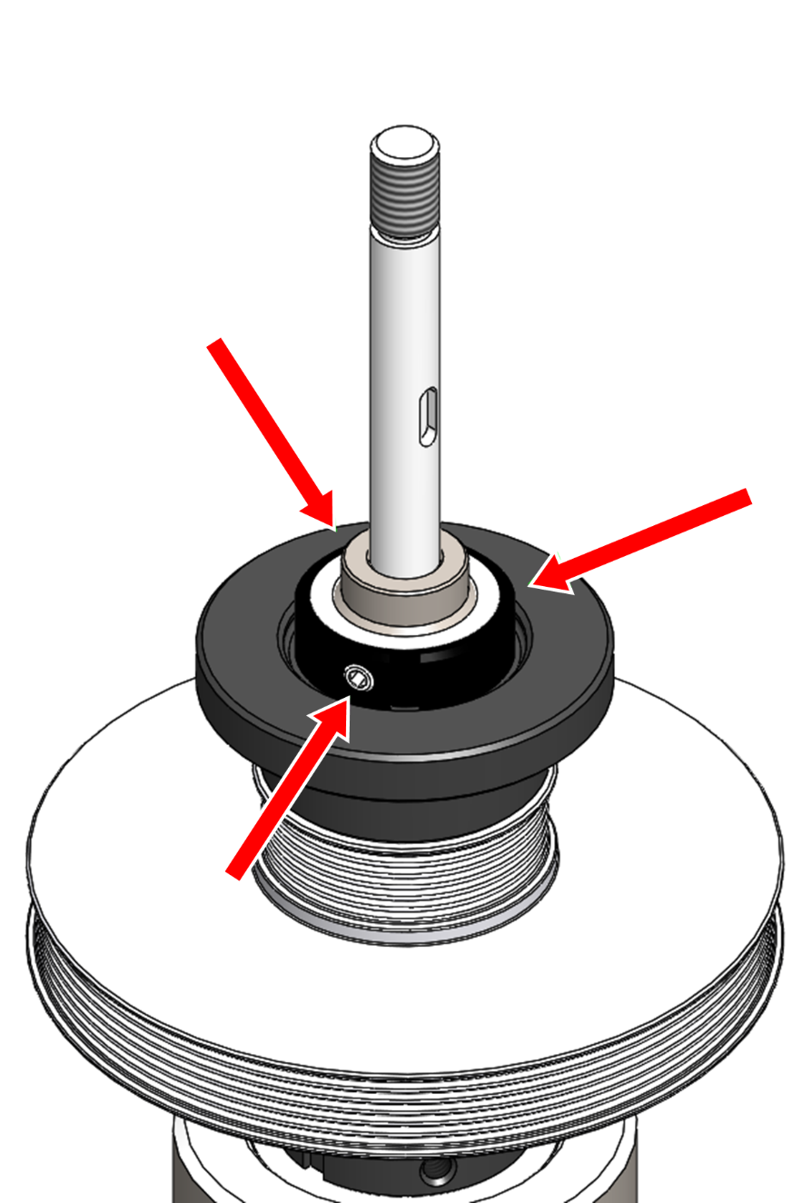
Install the pulley and power drawbar flange over the top of the spindle as shown in the following image.
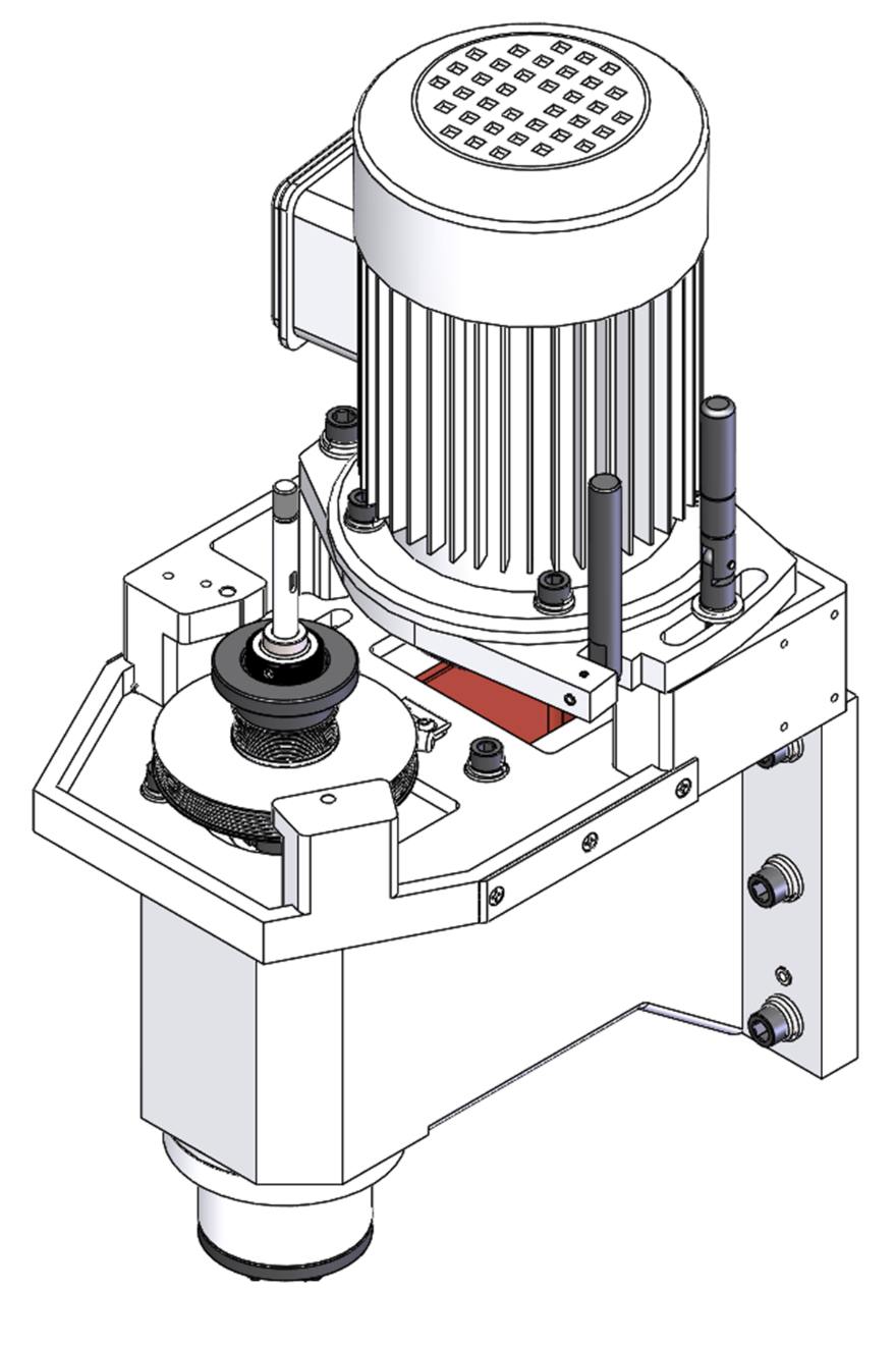
-
Reinstall the retention nut with the provided spanner wrench. Secure it by tightening its three set screws with a 3 mm hex wrench.
-
Install the disc spring guide and disc springs. Install disc spring compression nut, jam nut, and any shim washers. Verify that the drawbar preload witness marks are aligned.
NOTE: If the witness marks rubbed off during the installation, tighten the disc spring compression nut until it's snug, secure it with the jam nut, and make further adjustments after completing the Power Drawbar upgrade and/or installation. For information, see (refer to the section regarding insufficient preload of drawbar springs).
-
Install the provided 250 Poly-V belt in high belt position, and then apply tension with the belt tensioner.
-
Reconnect the motor quick-connect fitting.
Install the VFD (Serial Number MA10629 and Below Only)
WARNING! Electrical Shock Hazard: You must power off the machine before making any electrical connections. If you don't, there's a risk of electrocution or shock.
-
Power off the machine and the PathPilot controller.
-
Push in the machine's red Emergency Stop button, which removes power to motion control.
-
From the PathPilot interface, select Exit.
-
Turn the Main Disconnect switch to OFF on the side of the electrical cabinet.
-
-
Open the electrical cabinet door and identify the variable frequency drive (VFD).
-
Remove the lower wire trough cover from the electrical cabinet and set it aside.
-
Remove the access panel from the VFD with a flat-blade screwdriver and set it aside.
-
Remove all of the wires connected to the VFD with a flat-blade screwdriver, Phillips screwdriver, or torque driver as necessary.
-
Loosen the four mounting screws that secure the VFD to the electrical cabinet with a Phillips screwdriver. Set the mounting screws aside, and remove the VFD from the electrical cabinet.
-
Find the new VFD provided in this kit. Then, remove its access panel with a flat-blade screwdriver, and install it in the electrical cabinet with the four mounting screws that you set aside in Step 6.
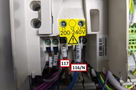
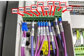
-
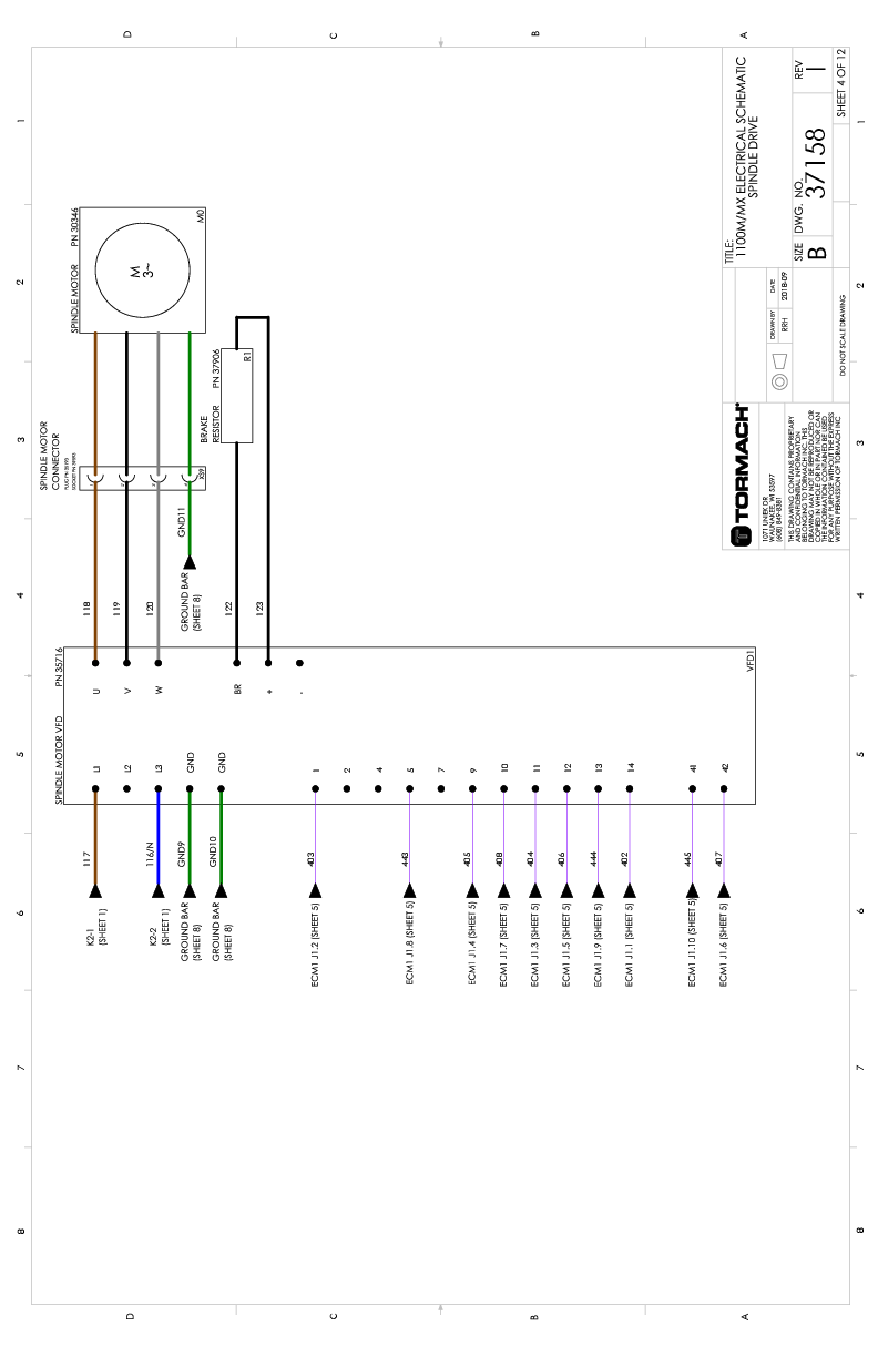
Install the wires that you removed from the old VFD in Step 5 into the new VFD. Use the following images (and the "Spindle Drive" wire schematic) to verify all connections.
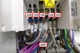
-
After double-checking and confirming wire connections, replace the access panel on the VFD.
-
Organize the wires from the VFD into the lower wire trough, and then replace its cover that you set aside in Step 8.
-
Close the electrical cabinet door.
Verify the Installation
-
Power on the machine and the PathPilot controller.
-
Turn the Main Disconnect switch to ON on the side of the electrical cabinet.
-
Twist out the machine's red Emergency Stop button, which enables movement to the machine axes and the spindle.
-
Press the Reset button.
-
Bring the machine out of reset and reference it.
-
-
From the PathPilot interface, on the Main tab, in the MDI Line DRO field, type Admin Config. Then select the Enter key.
In the dialog box, select OK. -
From the Tormach Machine Configuration screen, select 1100MX. Then, select Save and Start.
The PathPilot interface loads. -
Bring the machine out of reset and reference it.
-
On the Main tab, in the MDI Line DRO field, type Admin Encoder Test. Then select the Enter key.
Follow the on-screen instructions.
Resources
Spindle Drive
Machine Control Board (Sheet 5)
Spindle Head
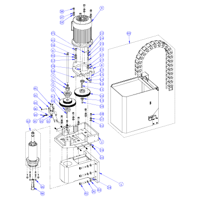
1100M
|
ID |
Description |
Quantity |
|
1 |
1100 Head Casting (PN 30323) |
1 |
|
2 |
1100 Spindle Motor Mount (PN 30324) |
1 |
|
3 |
Spindle Pulley1 |
1 |
|
4 |
Power Drawbar Flange1 |
1 |
|
5 |
Bearing Nut, M25 × 1.5, Set Screw (Angled)1 |
1 |
|
6 |
Drawbar, R8 (7/16-20), 305 mm (PN 38793) |
1 |
|
7 |
1 |
|
|
8 |
1100 Spindle Motor Pivot Plate (PN 30341) |
1 |
|
9 |
Spindle Motor, 1100 (PN 30346)Spindle Motor, 1100 |
1 |
|
10 |
Motor Pulley Spacer, 1100 (PN 30347) |
1 |
|
11 |
Key, 8 mm × 7 mm - 40 mm (PN 30348) |
1 |
|
12 |
Pivot Bushing (PN 30350)Pivot Bushing |
1 |
|
13 |
Pulley Washer (PN 30351) |
1 |
|
14 |
Tensioning Handle Detent Pin (PN 30336) |
1 |
|
15 |
Spring, 1 × 4.8 × 20 (PN 30338) |
1 |
|
16 |
Pivot Plate Pin (PN 30340) |
1 |
|
17 |
Spindle Motor Handle (PN 30339) |
1 |
|
18 |
Screw, Cone Point Set, M5 x 0.8 - 8 (PN 30337) |
1 |
|
19 |
Washer, Flat, M10 (PN 30325) |
4 |
|
20 |
1100 Motor Pulley (PN 37733) |
1 |
|
21 |
Pivot Plate Clamp Bolt (PN 30342) |
1 |
|
22 |
Pivot Plate Clamp Handle (PN 30345) |
1 |
|
23 |
Clamp Handle Detent Pin (PN 30343) |
1 |
|
24 |
Spring, 1 × 4.8 × 20 (PN 30344) |
1 |
|
25 |
Pin, 4 mm - 16 mm (PN 30395) |
1 |
|
26 |
Washer, Split Lock, M12 (PN 30321) |
7 |
|
27 |
Washer, Flat, M12 (PN 30322) |
1 |
|
28 |
Pin, Taper, 8 mm - 40 mm (PN 30320) |
2 |
|
29 |
Wear Strip, Spindle Door (PN 38451) |
2 |
|
30 |
Screw, M5 × 0.8 -14 (PN 37901) |
6 |
|
31 |
Spindle Lock Base (PN 38716) |
1 |
|
32 |
1100M Spindle Lock Bar (PN 38717) |
1 |
|
33 |
Washer, M6, Nylon (PN 38714) |
2 |
|
34 |
Screw, M8 × 1.25 - 10 mm (PN 31682) |
1 |
|
35 |
Spring, 6 mm × 20 mm (PN 31559) |
1 |
|
36 |
Ball, 6 mm, Steel (PN 38225) |
1 |
|
37 |
Washer, Split Lock, M10 (PN 31684) |
11 |
|
38 |
Screw, Socket Head Cap, M10 × 1.5 - 30 (PN 31894) |
10 |
|
39 |
Screw, Socket Head Cap, M8 × 1.25 - 20 (PN 31895) |
1 |
|
40 |
Washer, Flat, M12 (PN 32473) |
7 |
|
41 |
Screw, Socket Head Cap, M12 × 1.75 - 45 (PN 30349) |
1 |
|
42 |
Washer, Flat, M10 (PN 30919) |
6 |
|
43 |
Screw, Socket Head Cap, M12 × 1.75 - 50 (PN 32476) |
6 |
|
44 |
Screw, Socket Head Cap, M6 × 1 - 45 (PN 38715) |
1 |
|
45 |
Screw, Socket Head Cap, M6 × 1 - 20 (PN 30832) |
2 |
|
46 |
Key, 6 mm × 6 mm - 55 mm1 |
1 |
|
47 |
Spindle Pulley Spacer1 |
1 |
|
48 |
1 |
|
|
49 |
Screw, Socket Head Cap, M8 × 1.25 - 30 (PN 30544) |
6 |
|
50 |
Spindle Housing, 80 mm (PN 37701) |
1 |
|
53 |
Spindle Shaft, R8 (PN 37702) |
1 |
|
54 |
Spindle Nose Closure, 80 mm (PN 37703) |
1 |
|
55 |
1100 Bearing Spacing Sleeve (PN 37704) |
1 |
|
56 |
1100 Upper Bearing Shield (PN 37705) |
1 |
|
57 |
Nut, Bearing, M35 × 1.5, Set Screw (PN 37567) |
1 |
|
58 |
Pin, 3.5 mm × 9 mm (PN 38353) |
1 |
|
59 |
8 |
|
|
60 |
Screw, Socket Head Cap, M4 × 0.7 - 16 (PN 37751) |
8 |
|
62 |
R8-TTS Spindle Cartridge Assembly, 1100M (PN 37269)1 |
1 |
|
63 |
Spindle Cover Exploded View |
1 |
|
|
1R8-TTS Spindle Cartridge Assembly, 1100M (PN 37269) includes the following balanced and matched parts: #3, #4, #5, #46, and #47. |
|
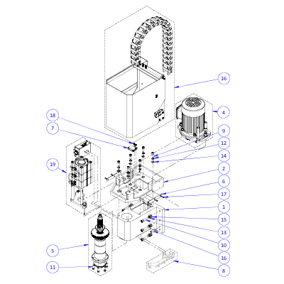
1100MX
|
ID |
Description |
Quantity |
|
1 |
1100 Head Casting (PN 30323) |
1 |
|
2 |
1100 Spindle Motor Mount (PN 30324) |
1 |
|
3 |
Spindle Cover, 1100 (37690) |
1 |
|
4 |
1100 Spindle Motor Pivot Plate Assembly (37714) |
1 |
|
5 |
BT30 Spindle Cartridge Assembly, 1100MX (PN 39590) |
1 |
|
6 |
Wear Strip, Spindle Door (PN 38451) |
2 |
|
7 |
Magnetic Encoder, Readhead (PN 38299) |
1 |
|
8 |
Mill Coolant Manifold Assembly (PN 38346) (Optional) |
1 |
|
9 |
Screw, Socket Head Cap, M10 × 1.5 - 30 (PN 31894) |
6 |
|
10 |
Screw, Socket Head Cap, M12 × 1.75 - 50 (PN 32476) |
6 |
|
11 |
Screw, Socket Head Cap, M8 × 1.25 - 30 (PN 30544) |
6 |
|
12 |
Washer, Split Lock, M10 (PN 31684) |
6 |
|
13 |
Washer, Split Lock, M12 (PN 30321) |
6 |
|
14 |
Washer, Flat, M10 (PN 30919) |
6 |
|
15 |
Washer, Flat, M12 (PN 32473) |
6 |
|
16 |
Pin, Taper, 8 mm - 40 mm (PN 30320) |
2 |
|
17 |
Screw, M5 × 0.8 -14 (PN 37901) |
6 |
|
18 |
Screw, Button Head Cap (Flanged), M5 × 0.8 - 10, Stainless Steel (PN 38205) |
2 |
|
19 |
1100MX/770MX Power Drawbar Kit (PN 50433) |
1 |
|
20 |
1100MX Spindle Belt (PN 50402) |
1 |
Spindle Cartridge
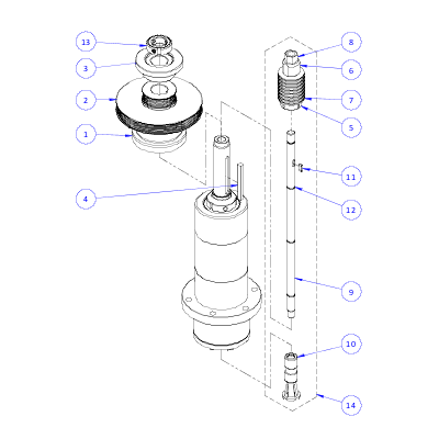
|
ID |
Description |
Quantity |
|
1 |
Magnetic Encoder, Spindle Ring (PN 38298) |
1 |
|
2 |
Spindle Pulley, 1100MX (PN 39576) |
1 |
|
3 |
Flange, BT30 Power Drawbar (PN 39577) |
1 |
|
4 |
Key, Straight, 6 mm × 6 mm - 64 mm (PN 39579) |
1 |
|
5 |
Disc Spring Guide, MX BT30 Spindle (PN 39597) |
1 |
|
6 |
Disc Spring Compression Nut, MX BT30 Spindle (PN 39598) |
1 |
|
7 |
Disc Spring, 40 mm × 20.4 mm × 2.0 mm × 3.10 mm (PN 39689) |
16 |
|
8 |
Nut, Jam, M12 × 1.75 (PN 39602) |
1 |
|
9 |
Drawbar, BT30 Spindle (PN 39574) |
1 |
|
10 |
Clamping Unit, BT30 (PN 39690) |
1 |
|
11 |
Key, Straight, 4 mm × 4 mm - 12 mm (PN 39601) |
1 |
|
12 |
O-Ring, 9 mm × 12 mm × 1.5 mm, Buna-N (PN 39584) |
3 |
|
13 |
Nut, Bearing, M25 × 1.5 (PN 39589) |
1 |
|
14 |
Drawbar Core Assembly, MX BT30 Spindle (PN 39599) |
— |
Troubleshooting
If you're having troubles with your BT30 spindle, read the following troubleshooting procedures:
Machining Operations are Loud ("Chattery")
|
Cause: Inappropriate cutting parameters or CAM settings. |
|
|
Probability |
How-To Steps |
|
High |
Verify that you're using the correct cutting parameters: use the feed rate and spindle overrides to adjust cutting parameters during operation. Confirm that tool offsets are correct. |
|
Cause: Worn or broken cutting tools. |
|
|
Probability |
How-To Steps |
|
High |
Inspect for worn or broken cutting tools, and replace as necessary. |
|
Cause: Swarf in the spindle or on the tool holder's shank. |
|
|
Probability |
How-To Steps |
|
Medium |
Inspect inside the spindle and on the tool holder's shank for swarf. If necessary, clean the components. Verify that the spindle and tool holder's contact surfaces are clean, dry, and free of grease or oil. |
|
Cause: Insufficient preload of drawbar springs. |
|
|
Probability |
How-To Steps |
|
Medium |
Verify that there's sufficient preload of the drawbar disc springs: Examine the shop air pressure, and verify that there's a minimum of 90 psi compressed air at the machine's FRL Filter-Regulator-Lubricator. If the machine's inlet air pressure is too low, it limits the machine's maximum tool clamping force. Tighten the drawbarspring stack compression nut and jam nut to increase the tool's clamping force. Adjust the power drawbar cylinder's piston bolt to maintain a 0.5 mm (0.20 in.) gap with the spindle's spring stack when there's no tool loaded in the spindle. Secure the piston bolt jam nut. Verify that the clamping force is increased as high as possible while still smoothly and reliably clamping and unclamping tool holders. |
|
Cause: Under- or over-tightened pull stud. |
|
|
Probability |
How-To Steps |
|
Medium |
Use the following items to tighten the pull studs to 40 Nm (30 ft lb) of torque: Socket, BT30 Pull Stud (PN 39420) Tool Tightening Fixture, BT30 (PN 39681) Torque wrench Under- or over-tightening the pull studs can cause poor contact between the tool holder and the spindle taper. |
|
Cause: Cracked or broken disc springs. |
|
|
Probability |
How-To Steps |
|
Low |
Remove the disc springs from the drawbar assembly and inspect them for damage. If you find any cracked or fractured springs, replace all eight16 disc springs in the stack with Power Drawbar Spring Washer (PN 31319)Disc Spring, 40 mm × 20.4 mm × 2.0 mm × 3.10 mm (PN 39689). |
|
Cause: Incorrect pull stud used for the machine. |
|
|
Probability |
How-To Steps |
|
Low |
Verify that all pull studs used in the machine are of the appropriate type. NOTICE! You must only use BT30-45° (ISO7388-3-JF30-45) type pull studs with this machine (Pull Stud, BT30-45° (PN 37553)). Other pull stud types or angles can cause damage to the pull stud clamping mechanism. If you find incorrect pull studs used in the machine, inspect the clamping mechanism for damage. If you find any damage, replace it with Clamping Unit, BT30 (PN 39690). |
Can't Load or Unload a Tool, or the Spindle's Drawbar Drags Against the Power Drawbar Cylinder's Piston Bolt
|
Cause: Insufficient shop air pressure. |
|
|
Probability |
How-To Steps |
|
High |
Examine the shop air pressure, and verify that there's a minimum of 90 psi compressed air at the machine's FRL Filter-Regulator-Lubricator. |
|
Cause: Insufficient or excessive preload of drawbar springs. |
|
|
Probability |
How-To Steps |
|
Medium |
Verify that there's sufficient preload of the drawbar disc springs: Examine the shop air pressure, and verify that there's a minimum of 90 psi compressed air at the machine's FRL Filter-Regulator-Lubricator. If the machine's inlet air pressure is too low, it limits the machine's ability to unclamp tools. If the spring stack drags against the power drawbar cylinder bolt, tighten the spring stack compression nut and jam nut to increase the tool's clamping force. If you cant' load or unload the tool, loosen the spring stack compression nut and jam nut to increase clamping mechanism travel. (Serial numbers ME10048/MF10028 and earlier, three-stack power drawbar only) Adjust the power drawbar cylinder's piston bolt to maintain a 0.5 mm (0.20 in.) gap with the spindle's spring stack when there's no tool loaded in the spindle. Secure the piston bolt jam nut. Verify that the clamping force is increased as high as possible while still smoothly and reliably clamping and unclamping tool holders. Repeat Steps 2-3 as necessary. |
|
Cause: Power drawbar cylinder piston is out of adjustment range. (For three-stack power drawbar cylinders only.) |
|
|
Probability |
How-To Steps |
|
Low |
Loosen the power drawbar cylinder's jam nut and adjust the piston bolt. Verify that the piston bolt sits within 0.5 mm (0.020 in.) of the spindle's spring stack when there's no tool loaded in the spindle. Secure the jam nut. |
|
Cause: The pull stud clamp has loosened from the end of the spindle's drawbar shaft. |
|
|
Probability |
How-To Steps |
|
Very Low |
Use the BT30 Clamping Unit Installation Tool (PN 50385) that was provided either with your machine or with your upgrade kit to verify that the clamping unit is securely tightened onto the drawbar shaft. If the clamping unit is loose: Uninstall the clamping unit and inspect it for wear or damage. If you find any damage, replace it with Clamping Unit, BT30 (PN 39690). Reinstall the clamping unit: apply medium-strength (blue) thread-locking compound to the threads, and tighten the clamping unit onto the drawbar shaft with the installation tool. |
To view a PDF version of your manual, go to Tormach document TD10705.
If you have additional questions, we can help. Create a support ticket with Tormach Technical Support at tormach.com/how-to-submit-a-support-ticket for guidance on how to proceed.