Operator Console Won't Work
Background
The console is an all-in-on controller with computer, touch screen, and some additional knobs. Its job is to run PathPilot and control your CNC machine. While its appearance is different from our other controllers, it functions the same: it controls your machine and provides you with a friendly user interface.
Tools
Digital multimeter
Small flat-bladed screwdriver
Metric hex wench set
Phillips screwdriver
Adjust the Touch Screen Sensitivity
Reason: The touch screen doesn’t respond to touch inputs on all or part of the screen’s surface.
Before you begin, make sure the plastic protective sheet is removed from your screen.
The touch screen is a resistive type to prevent accidental triggering from drops of coolant on the screen. The resistive touch screen may need its sensitivity adjusted when used in a shop space with very high or low humidity.
Verify that you have PathPilot v2.4.4 or higher installed on your controller.
From the PathPilot interface, in the MDI Line DRO field, type
Admin Touchscreen Sensitivity 1000and press Enter. You can use a value between 1 and 2047, but 1000 is generally sufficient for most shop spaces.
Console isn’t Receiving Power
Test the Power Button Functionality
Reason: The console doesn’t respond to the power button.
Examine the green ring around the power button. It should light up when you press the power button.
Examine Power Input to the Console
Reason: The console screen doesn’t display an image.
Examine the green LED on the power brick for the console. If it's not lit, examine and reseat the power cords to the power brick.
If further action is needed, inspect your machine's Accessory circuit breaker.
If the monitor and the controller both don't have power, examine the power cords for damage or exposed wires, and then reset the CB3 circuit breaker.
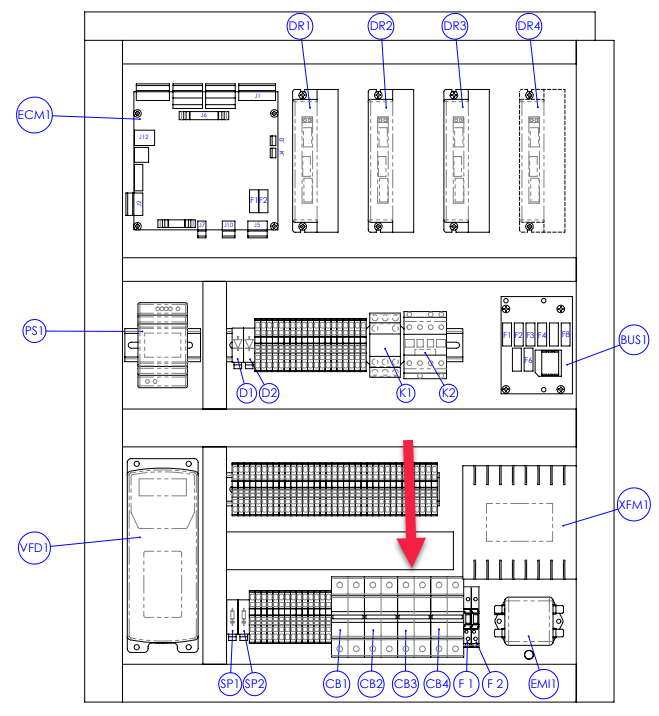
M/MX Electrical Cabinet
Configure the Display Output Settings in BIOS
Reason: The console screen turns on, but it’s scrambled or illegible.
Temporarily connect a separate VGA monitor to the console.
Power on the console, and, during the boot sequence, press the Delete key during to enter the BIOS menu.
From the Advanced tab, select Display Configuration.
Configure the display as follows:
Primary IGFX Boot Display: Auto
LCD Panel Type: 1280x1024 LVDS
Panel Channel: Dual Channel
Panel Color Depth: 24 Bit
Select the Esc key, go to Save and Exit, and select Save Changes and Reset.
This configuration problem can occur if your console has a CMOS battery failure. Replace the battery if it reoccurs.
RPM, Feed Override, or Max Velocity knobs don’t Work
Examine the Connectors on the Ribbon Cable
Reason: The ribbon cable connecting the knobs is disconnected.
Shipping can sometime cause connectors to become loose. Reseating the connectors will usually fix non-responsive override knobs.
Remove the rear panel of the console.
Examine the connectors on both ends of the cable going from J4 on the control board to the potentiometer board.
Examine the USB Connection to the Control Board
Reason: The circuit board is damaged.
Remove the rear panel of the console.
Examine the USB cable going from the header on the computer motherboard to connector J12 on the control board.
If you are able to move the RPM, Feed Override, and Max Velocity sliders with your finger or mouse, the USB daughter board will need to be replaced. (PN 39146)
Internal Operator Console Layout
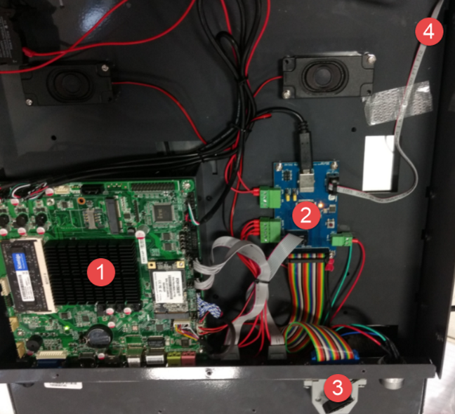
Inside Rear of Operator Console
Computer
VMC Console Controller (for all inputs and pendant control)
DB25 Connector for Pendant
LED light ribbon cable from control board to front panel of console
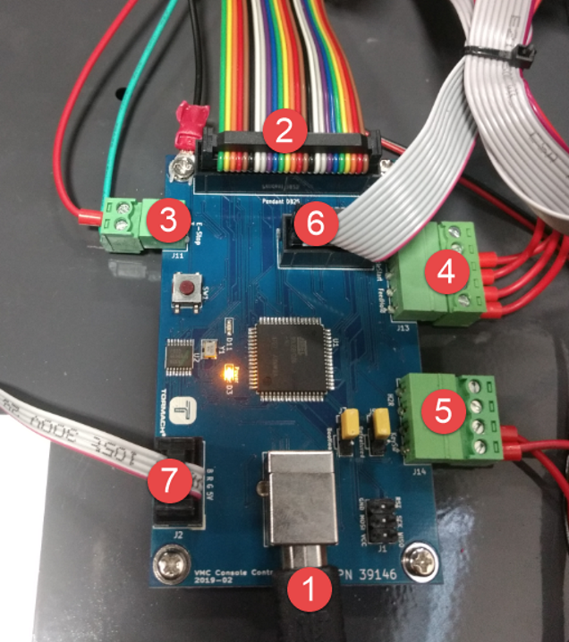
Daughter Board
USB connection from motherboard to control board
26 pin ribbon cable from DB25 connector for pendant
E-Stop circuit connection
Cycle Start and Feedhold button inputs
Key switch input
Potentiometer board ribbon cable
Front panel LED connector
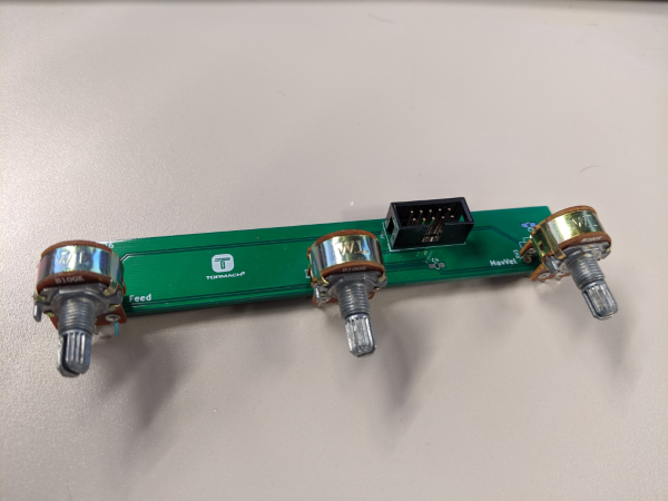
Potentiometer Board (39376)
The Potentiometer Board is accessed under the bottom angled sheet metal, on the rear of console.
Buttons Don’t Respond (Cycle Start, Feed Hold, LEDs, MPG)
Examine Wiring to Buttons
Reason: The Cycle Start or Feed Hold buttons don't are disconnected.
Shipping can sometime cause wire terminals to become loose. Reseating the wires will usually fix non-responsive buttons.
Remove the rear panel of the console.
Examine the wire inputs to connector J13 on the control board. If any wires are loose, tighten the screw terminals.
Using a continuity tester, measure the resistance between terminals 1 and 2 when Feed Hold is pressed and terminals 3 and 4 when Cycle Start is pressed.
If there's continuity at the terminals on the control board and the buttons still don't work, examine the USB cable to the control board.
If there's not continuity at the terminals when the buttons are pressed, remove the lower rear panel of the console and examine the screw terminals on the rear of the buttons themselves.
If you have tested all terminals and the buttons still don't have continuity when pressed, replace the buttons:
Feed Hold Button (PN 37363)
Cycle Start Button (PN 37362)
Examine the USB Connection to the Control Board
Reason: The control board is disconnected.
Remove the rear panel of the console.
Examine the USB cable going from the header on the computer motherboard to connector J12 on the control board.
Verify that the power LED on the console control board lights up when the console is turned on. If it doesn't light up, and you have confirmed the USB connection, replace the control board (PN 39146).