Purpose
This document gives instructions on installing and using the USB M-Code I/O Interface Kit to integrate external devices with the PathPilot controller.
Product Information
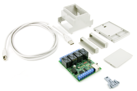
Product: USB M-Code I/O Interface Kit (PN 32616)
|
Quantity |
Description |
|
1 |
Enclosure |
|
1 |
Cover Plate |
|
1 |
Base |
|
1 |
DIN Rail Latch |
|
2 |
Terminal Block Cover |
|
1 |
USB Cable (PN 32370) |
|
1 |
Control Board (PN 32359) |
NOTE: If any items are missing, we can help. Create a support ticket with Tormach Technical Support at tormach.com/how-to-submit-a-support-ticket for guidance on how to proceed.
Before You Begin
The USB I/O module extends the inputs and outputs controlled by G- and M-code inside programs: once plugged into a PathPilot controller USB port, a USB I/O Module can expand the functionality of your machine.
WARNING! Operator Education: Before using this product, you must have adequate knowledge of electrical circuits, machine wiring, and proper safety procedures associated with a component-level product. Failure to do so could result in serious injury and/or machine damage.
Required Tools
This procedure requires the following tools. Collect them before you begin.
-
Razor blade
Assembly
-
Using a razor blade, trim the enclosure 1/16 inch at the locations indicated in the following image.
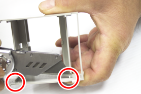
NOTE: The enclosure is symmetrical — you can trim either side.
-
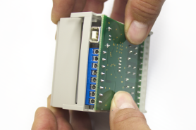
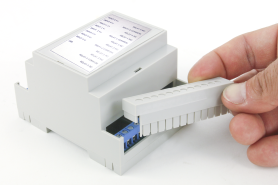
Place the control board into the enclosure as shown in the following image.
-
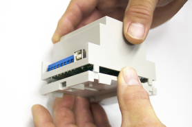
Snap the base on to the bottom of enclosure and attach the cover plate to the top of the enclosure. Make sure the text on the sticker matches the terminal block locations and the USB port on the control board.
-
Attach the terminal block covers over both terminal blocks.
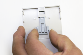
-
Snap the DIN rail latch into the bottom of the base; you can use the hook to mount the USB I/O module on the DIN rail in the electrical cabinet.
-
From the PathPilot interface, on the Settings tab, select the Enable the USB I/O checkbox.
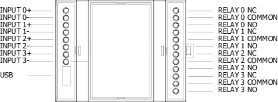
Input and Output Specifications
|
Inputs (Sinking) |
|
|
Minimum Current |
2 mA |
|
Current Short Circuit |
5 mA |
|
Open Circuit |
5 Vdc |
|
Outputs |
|
|
Rated Load |
10 A at 120 Vac; 8 A at 30 Vdc |
|
Maximum Switching Current |
10 A at 240 Vac (12 and 24 Vdc coil) |
|
Maximum Switching Current |
250 Vac, 125 Vdc (30 Vdc when UL/CSA standard is applied) AC: 10 A; DC: 8 A |
|
Maximum Switching Power |
1200 VA, 240 W |
|
Maximum Permissible Load |
100 mA at 5 Vdc |
Using Inputs
Inputs are used to control progress of the G-code and M-code programs. You can wire the USB I/O inputs in one of two ways:
-
Using an NPN (sinking) proximity switch
-
Using a snap action or micro switch
Input Modes
|
Mode |
Result |
|
L0 |
No waiting; returns immediately |
|
L1 |
Wait for input to rise |
|
L2 |
Wait for input to fall |
|
L3 |
Wait for input (high) |
|
L4 |
Wait for input (low) |
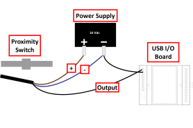
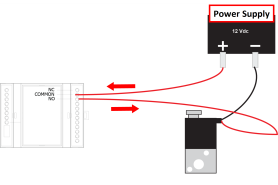
NPN (Sinking) Proximity Switch
You can use an NPN (sinking) proximity switch by sharing the power supply ground with the USB I/O board’s 0 input. Wire the proximity power and route the load to the 0+ input.
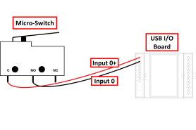
Snap Action or Micro Switch
You can use a snap action or micro switch to wire the input wires to the switch between Common and NO.
G-Code Example
NOTE: You can only use one subcall in each program.
%
(start)
N20 G90 G54 G64 G50 G17 G40 G80 G49
N30 G20 (Inch)
(Check input)
M66 P0 L3 Q100
o100 if [#5399 LT 0]
(msg,The input is missing or was applied too late)
M2
o100 End if
N39 M1 (Wait for cycle start)
(Hole machining call tool)
N40 G54
N50 T1 G43 H1 M6
(Center Drill)
N60 S5000 M3
N70 G0X-1.0625 Y0.3437 Z0.1754
N80 G98 G81 Z-0.031 R0.0394 F30
N90 X-0.7873 Y0.476
N100 G80
N110 M5 M9
N120 G30
N130 M30
%
G-Code Example Breakdown
(Start)- The program starts and defines the modal codes used.
(Check Input)-
M66 = Check Input
P0 = Input 1
L3 = Input High Mode
Q100 = time to wait before error
Code checks the #5399 parameter to verify the input 1 is present. If it is not, end the program and send an error to the status page after 100 seconds(Q100).
M66 = check Input
P0 = Input 1
L3 = Input High Mode
Q100 = time to wait before error
-If the input is present, the program proceeds to call the tool and drill the hole.
Using Outputs
The outputs are programmed using M64 (contact close) and M65 (contact open). There are four contacts, numbered from 0 to 3 on a mill and from 5 to 8 on a lathe. The contact is specified by the P word.
IMPORTANT! Lathes use different P calls than mills. Please read the following table carefully.
|
Input/Output Contacts for Mills |
Input/Output Contacts for Lathe |
|
P0 |
P5 |
|
P1 |
P6 |
|
P2 |
P7 |
|
P3 |
P8 |
Output Relay Examples
|
Activate the Output (M64) |
Deactivate the Output (M65) |
|
Activate the first relay on a mill: M64 P0 |
Deactivate the first relay on a mill: M65 P0 |
|
Activate the first relay on a lathe: M64 P5 |
Deactivate the first relay on a lathe: M65 P5 |
Syntax Limitations
There is only one P word and one relay per line.
IMPORTANT! Each relay command must be done on an individual line.
|
Correct Syntax |
Incorrect Syntax |
|
M64 P0 |
M64 P023 |
|
M64 P2 |
M64 P0 P2 P3 |
|
M64 P3 |
M64 P0 P2 P3 M65 PO |
Troubleshooting
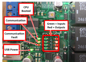
There are 12 diagnostic LEDs on the Control Board. These can be accessed by removing the cover plate.
Under normal conditions (i.e., after plugging the board into a USB port), the following happens on the control board:
-
The Input and Output LEDs flash
-
The CPU Booted LED comes on
-
The Power LED comes on
NOTE: The Communication LED does not flash until the USB I/O Module Control Board is both plugged in and enabled in PathPilot.
Important Considerations
Electrical Noise
Interruption of an electrical circuit (opening a relay contact) can create electrical noise that may disrupt USB communications. If there is any inductance (coil, motor, solenoid, etc.) on the load, include the appropriate RC filter across the load. These may be referred to as snubbers, suppressors, RC filter, or noise filters. For further information, refer to Tormach Service Bulletin SB0039, Problems from Electrical Noise.
Starting Up
Relay outputs may be pulsed for a fraction of a second when the controller is powered on.
Last State
The USB I/O driver maintains the last state if a G-code and/or M-code program is halted or reset. If the USB I/O board is disconnected from USB communications, the output relays are deactivated, but they are restored to their last state when the USB I/O board is reconnected via a USB.
To view a PDF version of your manual, go to Tormach document TD10163.
If you have additional questions, we can help. Create a support ticket with Tormach Technical Support at tormach.com/how-to-submit-a-support-ticket for guidance on how to proceed.