In This Section, You'll Learn:
About the basic operations required for most projects, organized as a suggested project workflow.
Plasma Settings Reference
Touch Switch Trigger Depth
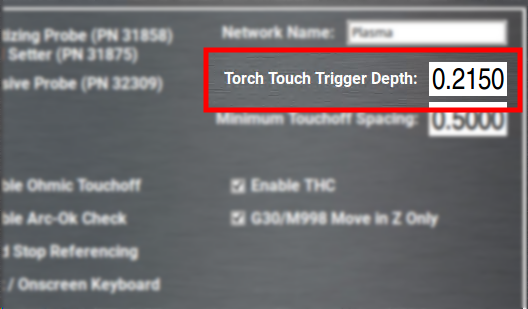
When using the physical touchoff switch for material height sensing, there's a certain amount of lost motion in the Z-axis between when the torch head touches the material and when the micro-switch in the torch lifter triggers.
It's important to set an accurate value for the distance between torch touch and touch switch triggering so that the initial pierce height can be correctly computed.
To set torch touch trigger depth:
-
Power on the machine and reference all axes.
-
From the PathPilot interface, on the Settings tab, disable Ohmic Touchoff.
-
Put a piece of material on the machine table and position the torch above it.
-
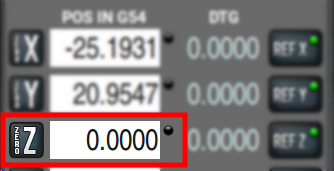
Using a slow jog speed (~5 IPM), jog the torch down until it's just contacting the material.
-
Zero your Z-axis at this position.
-
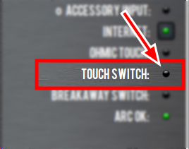
Switch to the Status tab and watch the Touch Switch LED. Very slowly, jog downwards until the LED comes on.
-
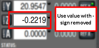
Note the value in the Z DRO field. This is your Torch Touch Trigger Depth. Convert this value to a positive number and enter it on the Settings tab.
-
Re-enable Ohmic Touchoff on the Settings page.
Minimum Touchoff Spacing
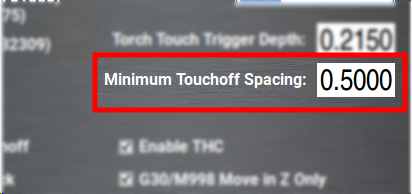
Minimum touchoff spacing is a time saving setting designed to avoid unnecessary probing during programs with a large number of individual cuts.
After the machine has probed for initial cut height, if the next cut begins within this distance it will be assumed that the material height is the same. This allows the machine to skip the probing routine and proceed straight to pierce height.
If your material is very flat and uniform, you can use a large distance for this setting (>2 in.). If your material is uneven or you would simply prefer to probe for height every time a cut begins, enter zero for this value.
Enable Ohmic Touchoff
This setting disables the ohmic sensing system entirely and relies solely on the physical touch switch for height sensing. This can be useful for cutting programs that result in water being repeatedly splashed into the torch nozzle, causing spurious probing trips.
NOTE: Do not disable ohmic touch-off when cutting very thin material. The weight of the torch will bend the material during probing and cause inaccurate pierce height.
Enable THC
Disabling this setting stops all dynamic height adjustment during cutting. The torch will stay at the same height for the length of a cut and not adjust to follow the contours of the material.
Enable Arc-Ok Checking
Hypertherm plasma sources supply an arc-ok signal to PathPilot when the cutting arc is fully established. When this setting is enabled, the machine will pause during a G16 pierce until is receives an arc-ok signal.
Disable this setting if your plasma source does not supply an arc-ok signal.
Create Programs with CAD/CAM
Converting DXF Files to G-Code
The simplest way to start cutting on the 1300PL is by using the conversational DXF import feature in PathPilot. We recommend this for beginners because it ensures that your G-code takes full advantage of PathPilot's AutoFS features and integrates the recommended feeds and speeds for Hypertherm plasma units.
To create DXF files for cutting:
-
Model the part as a flat body in SolidWorks. Use the sheet metal design tools or a extrude a flat sketch to create the geometry.
-
Export the DXF by right-clicking the desired surface in SolidWorks and selecting Export to DXF/DWG.
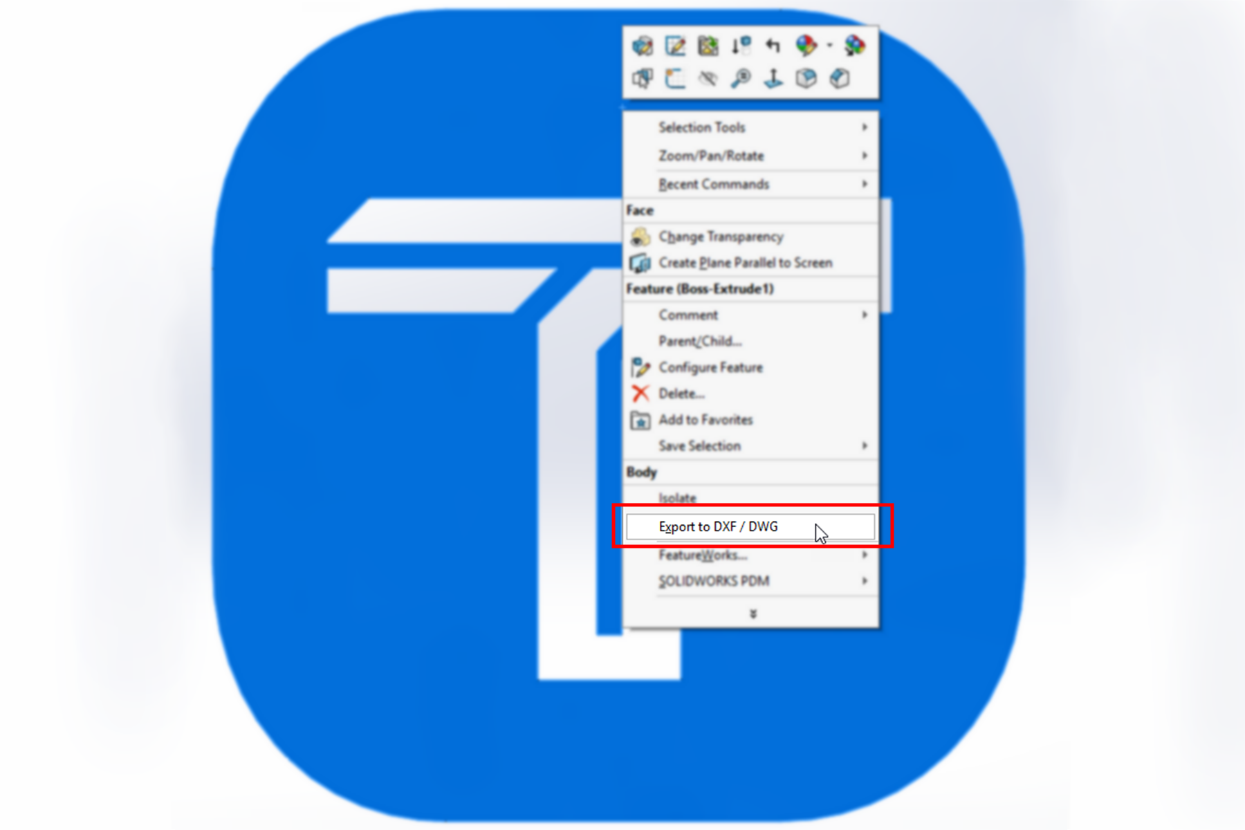
This approach avoids including unwanted items like axis markings, sketch boundaries, or notes in the DXF file.
-
Once your DXF is ready, import it into PathPilot using the conversational DXF import tool to quickly generate reliable cutting programs.
Using a Post-Processor
For more control over your cutting programs, you can use one of the following CAM programs, which have Tormach-supported post-processors:
-
Autodesk Fusion 360
-
Vectric Software
To export programs using Fusion or Vectric:
-
Select the Tormach post-processor in your CAM software.
-
Choose whether to:
-
Use the M200 AutoFS feature that allows PathPilot to choose feeds and speeds (based on the AutoFS dropdowns).
-
Override the AutoFS settings by applying the cut parameters from your CAM software.
NOTE: If you override AutoFS settings, you may experience unexpected cutting problems. Ensure that your cut settings align with Hypertherm’s recommendations.
To export programs using another CAM software:
-
Modify the post-processor to ensure the generated G-code matches the requirements in the example program in "Make Your First Cuts".
NOTE: Although PathPilot uses LinuxCNC, off-the-shelf post-processors will not work without adjustments. They lack the specific M- and G-codes that PathPilot uses for setting cut parameters, so using them as-is may produce unexpected results.
Select a Method for Initial Height Sensing (IHS)
Because plasma cutting workpieces are prone to heat-induced warping, it's common practice to probe the workpiece height before each cut using the initial height sensing (IHS) system. This guarantees a consistent pierce height, which prolongs consumable life.
The 1300PL has two methods of detecting the Z location of the workpiece before a cut. Choose which method to use based on your workpiece, cutting situation, and machine setup.
To select an IHS method:
-
From the PathPilot interface, on the Settings tab, select or clear the Enable Ohmic Touchoff checkbox.
For more information, see “Plasma Settings Reference”.
Physical Touch Switch
The first (and simplest) IHS method is the physical touch off switch in the torch lifter. A spring-loaded switch on the Z lead screw is triggered when the torch is pressed against the workpiece.
Use the physical touch switch when:
-
Your workpiece is thicker than 18 ga (1.2 mm).
-
Making many small cuts, where water is splashed into the torch head between cuts.
Ohmic Probing
The second, and more accurate, method of IHS is ohmic probing. Ohmic probing uses the conductivity of the workpiece to detect when the torch cap is touching it. Ohmic probing requires a very light touch and is very accurate, but can be incorrectly triggered by water splashing into the torch head.
Use ohmic probing when:
-
Your workpiece is thinner than 18 ga (1.2 mm).
-
Cutting large workpieces, where the torch is not crossing over open water between cuts.
Make Your First Cuts
Once you've verified all subsystems of the machine and plasma source, we recommend making a simple test program to test the cutting and torch height control systems. This is also a good quick-start tutorial on NC programming for the 1300PL.
Test G-Code
The following code will probe, set feeds from the AutoFS system, and then cut a 4" line from (0, 0) to (0, 4).
Open a text editor on your computer (like Notepad++), and save the following code in a file named test.nc.
G90 (Absolute Distance Mode)
G64 P 0.0050 Q 0.0050 (PathBlending)
G17 (XY Plane)
G54 (Set Work Offset)
T 1 M6 G43 H 1
G30 (Move Home)
G0 X0 Y0
M200 (AutoFS)
G15 (probe)
G16 (pierce)
G1 X0 Y4
M205 (Torch Off)
G30 (Move Home)
Code Breakdown
Preamble: This code block resets the modal state of the machine. It places the interpreter in absolute distance mode, sets reasonable values for smoothing, and selects the G54 work offset. For more detail on these G-codes, see the full PathPilot manual.
G90 (Absolute Distance Mode)
G64 P 0.0050 Q 0.0050 (PathBlending)
G17 (XY Plane)
G54 (Set Work Offset)
Tool Selection: Selects Tool 1 from the offsets table. On the plasma, convention is to use Tool 1 for the plasma torch.
T 1 M6 G43 H 1
Initial Move: Moves the torch to the home (G30) position in Z for safety and then performs a rapid move to coordinate (0, 0).
G30 (Move Home)
G0 X0 Y0
AutoFS: Uses the AutoFS material selector on the Main tab of PathPilot to set feed rate, pierce delay, pierce height and plasma amperage. No explicit feedrate needs to be specified for G1 moves since AutoFS sets this for you.
M200 (AutoFS)
Probe and Pierce: Probe the material surface using ohmic sensing. Once the torch detects the surface, Z0 for the current Work Coordinate System is set at the surface. After probing, G16 moves the torch to the pierce height set by AutoFS, fires the torch, waits for the AutoFS pierce delay and then moves to cutting height.
G15 (probe)
G16 (pierce)
Cut and Turn Torch Off: Performs a feed move from the current position (0, 0) to (0, 4). After the cutting move is complete, the torch is shut off and returned to the G30 home position.
NOTE: You might notice that your torch pauses and continues to blow air for 10-20 seconds. This is a cool down procedure designed by the plasma source manufacturer.
G1 X0 Y4
M205 (Torch Off)
G30 (Move Home)
Run the Test Program
IMPORTANT! Before running your test program, make sure you have completed all steps in Verify the Installation.
-
Find a piece of scrap sheet steel large enough to make a 4" test cut.
-
Put the metal on the cutting table and connect the ground clamp to it.
-
Bring PathPilot out of the Reset state and home the machine.
-
Power on plasma source.
-
Jog the cutting torch to a place at least 5" past the edge of the plate in Y- (towards the operator side of the machine).
-
Check that your current Work Coordinate System is G54 to match the test cutting code.
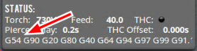
If it isn't, type G54 into the MDI Line DRO field. Then select the Enter key.
-
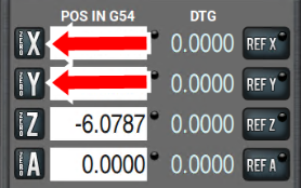
Select Zero X and Zero Y to set your work coordinate system zeros.
-
Copy your G-code from a USB drive and load it into PathPilot.
-
Select the material you're using for your cut test in the AutoFS dropdown on the Main tab.
-
Adjust your plasma source to the amperage shown in the AMPS DRO field.
-
Select Cycle Start.
The machine performs the test cut that you programmed.
Use the AutoFS Material Picker
PathPilot on the 1300PL is designed so that you don't need to manually program feeds and speeds in your G-code. Instead, feed rate, amperage, pierce parameters, and torch height control voltage are all set at program run-time using automatic look-up tables based on the material you're cutting.
AutoFS is designed so that you can export a program once from your post-processor and run it multiple times with different materials, all without re-posting. All material-specific machine parameters are set by the M200 AutoFS M-code (rather than directly programmed in the G-code).
Writing G-Code with AutoFS
A standard block of G-code before a cutting operation might look like this:
M210 P123 (Set THC voltage to 123v)
M211 P45 (Set plasma source to 45A)
M207 P0.15 (Set pierce height to 0.15")
M208 P0.08 (Set cut height to 0.08")
M209 P2 (Set a two second pierce delay)
F225 (Set cutting feed rate of 225 IPM)
G15 (Perform ohmic probe)
G16 (Pierce and start cutting)
The block of code shown above is totally valid and can be used if you prefer to hard code your cutting parameters. Alternatively, the code shown above can be replaced with the following when AutoFS is being used:
M200 (Set cutting parameters from AutoFS tables)
G15 (Perform ohmic probe)
G16 (Pierce and start cutting)
Using AutoFS
-
On the Settings tab, select which plasma source you're using from the Auto FS Plasma Source drop-down menu.
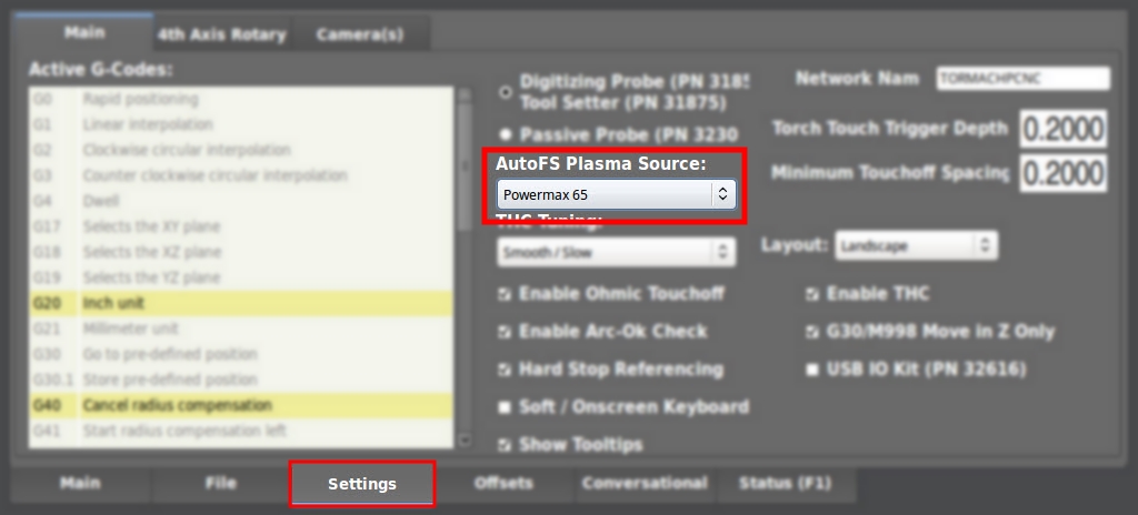
-
Before running your program, select the material you're cutting from the AutoFS dropdowns on the Main tab of PathPilot.
The DROs turn green, which indicates that they were automatically set.
With a material selected, the next time an M200 code is encountered in a program, PathPilot will set all of the cutting parameters for that material.
Creating Custom AutoFS Presets
Since your shop air supply and cutting conditions might differ from those used to create the AutoFS presets, you can save your own custom settings for a material at any time.
To create new AutoFS presets:
-
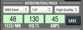
From the Main tab, select the material you're cutting from the AutoFS dropdowns, and then type your cut parameters into the DRO fields.
-
Select Save.
The values are stored as a new preset for that material.
Deleting Custom AutoFS Presets
-
From the File tab, navigate to the fs_tables folder, and open the plasma_user_fs_data.csv file.
-
Highlight the line of the preset you want to delete and delete it. Then, save the file.
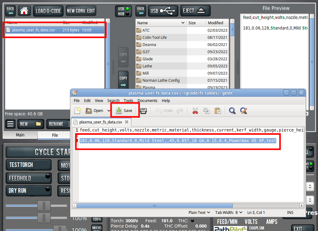
NOTE: This file is read on boot only, so the preset remains visible until the controller is power cycled.
Looking for more information?
This is a section of the 1300PL operator's manual. To view the whole manual, go to Tormach document UM10720.
If you have additional questions, we can help. Create a support ticket with Tormach Technical Support at tormach.com/how-to-submit-a-support-ticket for guidance on how to proceed.