System Basics
In This Section, You'll Learn:
About the main components of the machine and how it moves.
Before operating the machine in any way, you must read and understand this section.
System Reference
Water Table
The machine table is 51.2" x 51.2" (1300 mm x 1300 mm). It can be moved backwards in the frame by up to 10" (250 mm) to provide an open area for cutting large or bulky objects that do not fit on top of the water table (items like large pipes or weldments).
NOTE: Make sure you do not forget to connect the ground clamp to the workpiece when cutting something that is too large for the water table.
The water table has an internal depth of about 5.2" (132 mm) and a maximum water capacity of 59 US gallons (223 liters).
Don't put more than 750 lb (340 kg) on the machine table (excluding water). Always verify that the workpiece and work-holding devices are centered on the machine table.
Always lock the water table in the forward or backwards position before running a program.
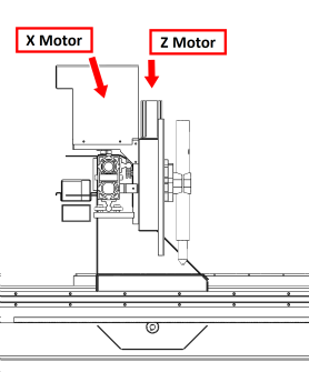
Z Torch Head
The Z Torch head is responsible for control of torch height during cutting. It also contains the magnetic torch breakaway head and the proximity sensor required to detect a breakaway.
The Z head can travel 3.9" (100 mm) vertically, which allows for cutting bulky items or even changing the height of the slats in the water table if cutting conditions require it.
The Z head is also responsible for material touch-off at the start of a cut. Touch-off on the material can occur one of two ways:
Ohmic Touchoff
Physical Touch Switch
Ohmic Touchoff
Ohmic Touchoff is a sensitive and precise method of Z positioning for initial cut height. The cap on the end of the torch is made of a conductive material (usually copper) that is linked to the machine's control system through a removable lead.
When the head touches the workpiece during the initial probing move before a cut, continuity between the torch cap and ground (through the plasma ground clamp) is detected by the control system.
This system works well for thin workpieces like 20 ga. (1 mm) and thinner sheet metal, where the weight of the torch during probing could otherwise deform the sheet metal before the probe switch triggers.
Physical Touch Switch
The physical touch switch acts as a backup to the ohmic touch system. It consists of a micro-switch inside the lifter head that detects when the spring-loaded lead nut on the Z lifter is pushed back by contact with the workpiece.
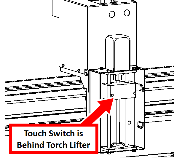
The physical touch switch will automatically be used when the ohmic touch switch does not trigger first. This can be useful in situations like cutting painted metal, where no continuity with the workpiece is possible.
NOTE: Even though the physical touch switch allows you to touch off on painted metal, you will still need to grind away enough paint for the ground clamp to make contact!
Basic Controls Reference
To safely and effectively operate your machine, you must become familiar with how it moves. The machine has two forms of basic controls: machine controls and the PathPilot interface.
Machine Controls
The following controls energize the machine's control electronics:
The Main Disconnect switch, located on the front of the electrical cabinet.
The Main Disconnect switch has two positions: OFF and ON. When it's in the OFF position, it separates the other machine control electronics from the mains electrical supply. When it's in the ON position, the other machine control electronics are able to receive power.
WARNING! Before opening the electrical cabinet for maintenance or troubleshooting, you must lockout the mains power: Turn the Main Disconnect switch to the OFF position, and secure an approved lockout device through the lockout rings at the bottom of the switch.
The operator box — which contains the blue Reset button and the red Emergency Stop button — located on the front of the machine.
When pushed in, the Emergency Stop button interrupts power to the axis drives, and stops the machine’s motion. When the Emergency Stop button is twisted out, press the Reset button to enable the machine, allowing axis motion. The Reset button’s LED turns on when the machine is enabled and the axis drives receive power.
PathPilot Interface
PathPilot is the primary means by which you interact with your machine. PathPilot controls all of the automatic motion of the machine axes and spindle, as well as some accessories. The PathPilot control system consists of:
Controller Arm
Controller
(Optional)Jog Shuttle
Keyboard
Monitor or (Optional)Touch Screen Kit
Mouse
Connectors Reference
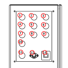
Figure 1: Connector panel on the upper rear of the electrical cabinet.
X-Axis Motor Power Connector
Two pin power connector for the X-axis servo.Y-Axis Motor Power Connector
Two pin power connector for the Y-axis servo.Ohmic Cap Connector
Input for the ohmic probing circuit. Also connects machine grounds to the cabinet ground.X-Axis Motor Control Connector
Eight pin control connector for the X-axis servo.Y-Axis Motor Control Connector
Eight pin control connector for the Y-axis servo.Limit Switch Inputs
Limit switch inputs from the Z Touch Lifter. Also contains the input for the torch breakaway and touch switches.Z-Axis Motor Connector
The Z-Axis stepper motor output.A-Axis Motor Connector
The A-axis motor connector is used to connect to a rotary 4th axis (used for indexing or continuous 4th axis machining).24v Accessory Output
24v outputs used to control things like pneumatic solenoids for air engravers or lifters.Emergency Stop Input
Input cable from the operator panel containing the reset button and emergency stop.Plasma Source Control
Control signals for the plasma source. Outputs an arc on-off signal. Torch voltage and arc-ok feedback are received here. Reference "Plasma Source Control".Accessory Input
The accessory input is used to connect accessories (like probes, tool setters, and tool touch plates) to the machine.Controller Communications Port
The controller communications port is used to connect the PathPilot controller to the machine. The controller communications port (and the cable that connects to it) sends all communication between the PathPilot interface and the machine.
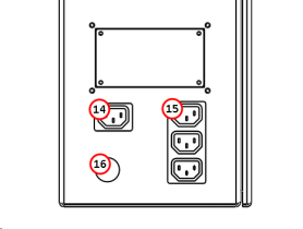
Figure 2: Connector panel on the lower rear of the electrical cabinet.
Switched Power Port
The IEC-320 switched power port is used to supply power to accessories that can be controlled by PathPilot such as a downdraft extractor fan. This outlet outputs the same voltage as the machine input voltage (230 VAC).Accessory Power Port
The IEC-320 accessory power ports are used to supply power to peripheral accessories (like the PathPilot controller and monitor). These outlets output the same voltage as the machine input voltage (230 VAC).Electrical Power Input
Input power lead for the electrical cabinet.
Plasma Source Control
The 1300PL uses a 7-pin connector for controlling the plasma source. A 7-pin to 14-pin cable is included with your machine to control Hypertherm plasma sources.
The pin-out of the 7-pin connector on the electrical cabinet is as follows:
Pin | Type | Signal | Notes |
1 | Output | Start Plasma | Dry contact closure. Closed relay signals plasma on. |
2 | |||
3 | Input | Arc Voltage - | An internal 50:1 voltage divider in the plasma source is required. |
4 | Arc Voltage + | ||
5 | Input | Arc-Ok | Expects dry contact closure at plasma source. Closed contacts signal arc-ok. |
6 | |||
7 | Not Used |
|
|
The pin-out of the 14-pin Hypertherm connector on the end of the cable is as follows:
Pin | Type | Signal | Notes |
3 | Output | Start Plasma | Dry contact closure. Closed relay signals plasma on. |
4 | |||
5 | Input | Arc Voltage - | An internal 50:1 voltage divider in the plasma source is required. |
6 | Arc Voltage + | ||
12 | Input | Arc-Ok | Expects dry contact closure at plasma source. Closed contacts signal arc-ok. |
14 |
Looking for more information?
This is a section of the 1300PL operator's manual. To view the whole manual, go to Tormach document UM10720.
If you have additional questions, we can help. Create a support ticket with Tormach Technical Support at tormach.com/how-to-submit-a-support-ticket for guidance on how to proceed.