In This Section, You'll Learn:
About the standards and safety precautions associated with this machine.
Before operating the machine in any way, you must read and understand this section.
Safe operation of the machine depends on its proper use and the precautions you take. Only trained personnel — with a clear and thorough understanding of its operation and safety requirements — shall operate this machine.
Intended Use
This machine is intended for general-purpose, computer numerical control (CNC) machining in the following applications:
-
Educational environments
-
Hobby applications
-
Light production
-
Prototyping
-
Research and development
-
Secondary operations
The intended use includes:
-
Appropriate workholding, toolholding, tooling, coolant systems, and machining parameters.
-
Machining of conventional, non-abrasive materials such as ferrous and non-ferrous metals below 60 HRC, woods, and plastics.
The intended use does not include machining materials that:
-
Are abrasive, carcinogenic, explosive, flammable, radioactive, or toxic
-
Produce aerosols or fine particulates when machined
The intended use does not include the following materials (not a full list):
-
Beryllium and its alloys
-
Ceramics
-
Fiberglass
-
G10 fiberglass laminate
-
Graphite
-
Magnesium and its alloys
To safely operate products, you must obey all safety precautions and warnings that are on the machines and in the documentation.
Machine Standards
When installed and operated as intended (see "Intended Use"), this machine complies with the following standards. You must follow the requirements listed in the standards so that the machine remains compliant.
American National Safety Institute (ANSI)
-
ANSI B11.TR3-2000 Risk Assessment and Risk Reduction — A Guideline to Estimate, Evaluate, and Reduce Risks Associated with Machine Tools
-
ANSI B11.8-2001 Safety Requirements for Manual Milling, Drilling, and Boring Machines with or without Automatic Control
-
ANSI B11.19-2010 Performance Requirements for Safeguarding
-
ANSI B11.23-2002 Safety Requirements for Machining Centers and Automatic Numerically Controlled Milling, Drilling, and Boring Machines
Occupational Safety and Health Administration (OSHA)
-
OSHA 1910.212 General Requirements for All Machines
-
OSHA 3067 Concepts and Techniques of Machine Safeguarding
Safety Overview
Any machine tool is potentially dangerous. A CNC machine's automation presents added risk not present in a manual machine.
Before operating the machine in any way, you must read and understand this section.
-
Read and understand all safety messages used in this document.
-
Locate and understand all safety decals on the machine.
-
Locate and become familiar with all information decals on the machine.
Safety Messages
The following examples show the standard safety message types used to draw your attention to important information. The standards distinguish between personal injury safety messages and property damage warning messages.
Personal Injury
Personal injury safety messages have safety alert symbols and the following hazard level labels:
DANGER! Indicates a hazard with a high level of risk which, if not avoided, will result in death or serious injury.
WARNING! Indicates a hazard with a medium level of risk which, if not avoided, can result in death or serious injury.
CAUTION! Indicates a hazard with a low level of risk which, if not avoided, can result in minor or moderate injury.
Property Damage
NOTICE! Indicates a hazard which, if not avoided, can cause property damage.
Safety Decals
Before operating the machine in any way, you must read and understand all installed safety decals on the machine and equipment. Do not remove any safety decals. If any safety decals become worn or damaged, contact Tormach Technical Support for guidance on receiving replacement decals.
The following types of safety symbols are on the decals:
-
Warning

This symbol indicates a hazard which, if not avoided, can result in personal injury or property damage.
-
Prohibition

This symbol indicates an action that shall not be taken or that shall be stopped.
-
Mandatory Action

This symbol indicates an action that you must take to avoid a hazard.
On the Electrical Cabinet Door
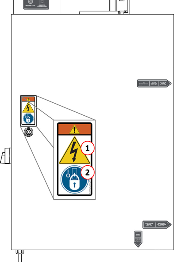
-
WARNING! Electrocution Hazard. Points in the electrical cabinet contain high voltages, which can electrocute or shock you, causing death or serious injury. Even after the machine is powered off, electronic devices in the electrical cabinet can retain dangerous electrical voltages. Use caution when servicing the machine inside the electrical cabinet.
-
Lockout/Tagout. Before servicing the machine, you must power off the machine and use an approved lockout/tagout device to secure the Main Disconnect switch in the OFF position. Points in the electrical cabinet contain high voltages, which can electrocute or shock you, causing death or serious injury.
Next to the Main Disconnect
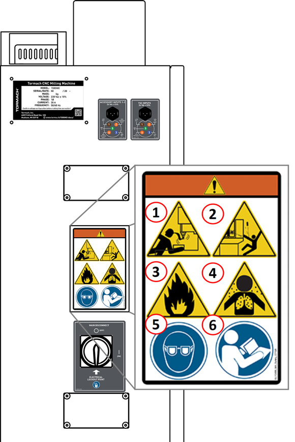
-
WARNING! Entanglement / Entrapment Hazard. The machine operates under automatic control — it can start at any time and crush, cut, entangle, or pinch body parts. Always keep clear of positions on the machine where unexpected or unintended machine motion could cause harm. Before operating this machine in any way, you must verify that all operators know the location of the machine's Emergency Stop button.
-
WARNING! Ejection Hazard. Fixtures, tooling, workpieces, or other loose items can become dangerous projectiles and can cause death or serious injury. Before operating this machine in any way, you must verify that you have appropriately secured all components.
-
WARNING! Fire Hazard. The machine and its enclosure are not designed to contain fire or explosions. Only use materials and coolants that are intended for the specific machining operation. Never use flammable or explosive items.Before operating the machine in any way, you must read all Safety Data Sheets (SDSs) for any workpiece materials, coatings, coolants, lubricants, and other consumables used.
-
WARNING! Inhalation Hazard. The machine and its enclosure do not protect you from airborne particulates. Chips, dust, and vapors from certain materials can be toxic or otherwise harmful. Before operating the machine in any way, you must read all Safety Data Sheets (SDSs) for any workpiece materials, coatings, coolants, lubricants, and other consumables used.
-
Personal Protective Equipment: Eyes. Prevent injury by always wearing protective safety eyewear. Before operating this machine in any way, you must verify that your eyewear is impact-resistant and rated for ANSI 787+.
-
Operator Knowledge. Before operating this machine in any way, you and all other operators must read and understand all instructions. If you don't, there's a risk of voided warranty, property damage, serious injury, or death.
On the Spindle Nose
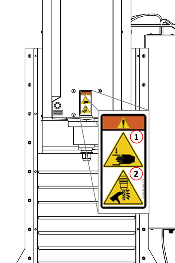
-
WARNING! Crush Hazard. Moving parts can entangle, pinch, or cut you, causing death or serious injury. Before operating this machine in any way, you must verify that all body parts, long hair, and clothes are clear of the machine's extent of motion.
-
WARNING! Cut Hazard. Tools and swarf can cut you. Only hold tools by the tool holder. Before inserting or removing tools from the machine, you must verify that all motion is completely stopped.
Information Decals
Before operating the machine in any way, you must locate and become familiar with all installed information decals on the machine and equipment.
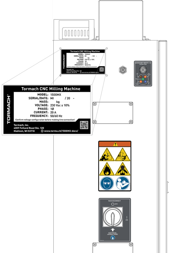
Serial Number Plate
The serial number plate is on the side of the electrical cabinet, near the Main Disconnect switch.
Machine Safety
Before operating the machine in any way, you must read and understand this section.
Safe operation of the machine depends on its proper use and the precautions you take. Only trained personnel — with a clear and thorough understanding of its operation and safety requirements — shall operate this machine.
General Shop Safety
-
Verify that only qualified machinery maintenance professionals install, set up, or perform maintenance on this machine.
-
Keep the work area well-lit. Use additional lighting if needed. The work area should be illuminated to a minimum of 500 lx.
-
Keep the work area temperature- and humidity-controlled.
-
Remove loose-fitting clothing, neckties, gloves, and jewelry.
-
Tie up long hair and secure it under a hat.
-
Wear safety eye protection rated for ANSI Z87+.
-
Wear closed-toed safety shoes.
-
Wear ear protection when you expect the machine or the machining processes to exceed safe exposure limits. For information, see "Noise Exposure".
-
Keep the work area clean and free of clutter. Machine motion can occur if controls are accidentally activated.
-
Immediately clean up spills after they occur.
-
Never operate the machine after consuming alcohol or taking medication that could prevent you from safely operating the machine.
-
Never operate the machine while tired or otherwise impaired.
-
Never operate the machine in an explosive (ATEX) atmosphere. Such explosive atmospheres include explosive gases, vapors, mists, powders, and dusts.
Operational Safety
General
-
Understand that the machine is automatically controlled and can start at any time.
-
If anyone enters the machining envelope during operation, immediately push in the Emergency Stop button. In case of a power loss, turn the Door Switch Override to the Unlocked position and open the enclosure doors.
-
Become familiar with all physical and software controls.
-
Always use a chip scraper or brush when clearing away chips, oil, or coolant.
-
Examine all tools, fixtures, workpieces, and guarding for signs of damage. Replace any damaged components as soon as you find them.
-
The enclosure and other guards may not stop all types of projectiles, like broken tools or loose workpieces.
-
Stop the machine and verify that all machine motion has completely stopped before doing any of the following:
-
Adjusting a part, fixture, or coolant nozzle.
-
Changing belt or pulley positions.
-
Changing tools or parts.
-
Clearing away chips, oil, or coolant.
-
Reaching into any part of the machine's motion envelope.
-
Removing protective shields or safeguards.
-
Taking measurements.
-
Doing any other action inside the machine enclosure.
-
-
Use flood or MQL (mist) coolant as required by the machining operation.
-
Only use coolants designed for metal working applications such as soluble oils, semi-synthetic, or synthetic coolants.
-
Read the Safety Data Sheet (SDS) for all workpiece materials, coatings, coolants (flood or MQL), lubricants, and other consumables. Chips, dust, and vapors from certain materials can be toxic or otherwise harmful.
-
Understand that this product can expose you to chemicals which are known to the State of California to cause cancer and birth defects or other reproductive harm. For more information, go to www.P65Warnings.ca.gov.
-
Dispose of scrap and swarf according to local regulations and guidelines.
-
Thoroughly read all safety precautions and instructions.
-
When machining an unproven program, use feed, speed, and maximum velocity overrides, Distance-to-Go (DTG) displays, single block, feed hold, and other control features.
-
Follow all appropriate "Machine Standards".
-
Never enter the machining envelope.
-
Never reach around a guard.
-
Never allow the machine to run unattended.
-
Never obstruct the Emergency Stop button or any other controls.
-
Never allow untrained operators to install, operate, or maintain the machine.
-
Never modify, defeat, or bypass safety devices or interlocks.
-
Never machine abrasive, carcinogenic, explosive, flammable, radioactive, or toxic materials. Such materials include, but are not limited to:
-
Beryllium and its alloys
-
Ceramic
-
Fiberglass
-
G10 fiberglass laminate
-
Graphite
-
Lead and its alloys
-
Magnesium and its alloys
-
-
Never allow swarf to accumulate on or within the machine.
-
Never use flammable liquids (like alcohol, diesel fuel, or kerosene) in the machine’s coolant system.
-
Never use water, coolants without rust inhibitors, or straight cutting oil in the machine’s coolant system.
Tooling
-
Use appropriate speeds, feeds, and cutting parameters for your machine, machine operation, material, and tooling.
-
Use tools and tool holders that are suitable for the current operation.
-
Examine tools for signs of damage. Replace any damaged tools as soon as you find them.
-
The enclosure and other guards may not stop all types of projectiles, like broken tooling.
-
Never use unbalanced tooling or spindle fixtures.
-
Never use tools that are larger or longer than necessary.
-
Never use tools at speeds above their operational limits.
Workholding
-
Secure workpieces with appropriate workholding devices (like a milling vise or strap clamps).
-
Verify that the workpiece is adequately secured.
-
Position clamps and workholding devices clear of any tool paths.
-
Remove cutoff workpieces and other large chips before starting the machine.
-
Never leave tools, stock, or other loose items inside the machine.
Electrical Safety
WARNING! Electrical Shock Hazard: You must power off the machine before making any electrical connections. If you don't, there's a risk of electrocution or shock.
-
Power off the machine before servicing.
-
Use an approved lockout/tagout system to secure the machine's Main Disconnect in the OFF position before servicing the machine.
-
Understand that certain electrical components can retain dangerous electrical voltages, even after the machine is powered off and all power is removed from the system.
-
Understand that certain installation, maintenance, and troubleshooting procedures — for the machine and certain accessories — require access to or modification of wiring inside of the electrical cabinet. Only qualified electrical machinery technicians shall perform these procedures.
-
Confirm that the mains voltage conforms to requirements before connecting the machine.
For more information, see “Electrical and Power Requirements”. -
Confirm that the machine installation meets all codes and regulations of your locality.
-
Confirm that electrical connections are performed by a certified electrician.
-
Lock the electrical cabinet door and remove the keys when the machine is not being serviced to prevent unqualified or unauthorized personnel from accessing the electrical cabinet.
-
Never operate the machine with the electrical cabinet door open.
-
Never reach into the electrical cabinet with the machine powered on.
-
Never modify the machine's electronics.
-
Never drill into the electrical cabinet.
Noise Exposure
CAUTION! Noise Exposure Hazard: If you expect the machine or the machining processes to exceed safe exposure limits, you must wear ear protection.
With the axes moving and the spindle rotating (but not cutting), the emission sound pressure level at the operator control station is 70 dB(A).
Emission sound pressure levels vary depending on the machining processes. Factors that influence the actual level of noise exposure may include:
-
Characteristics of the work room
-
Other sources of noise (like the number of machines, or other adjacent processes)
The permissible noise exposure level may vary between countries. You must evaluate of the hazard and risk based on your locality, and mitigate as necessary.
Operating Modes Reference
This machine has two modes: run mode and setup mode. In both modes, you must close and lock the enclosure doors before starting a program. In setup mode, experienced operators can perform maintenance or set up jobs while the enclosure doors are open. To access setup mode, you must have a key.
For unrestricted machine motion to occur, you must do the following in the order listed:
-
Close the enclosure doors.
-
Command the machine to move or start a program. The enclosure doors automatically lock before any machine motion occurs.
Run Mode (Mode 1)
When the enclosure doors are open, and the machine is in run mode, no motion can occur. For example, you can't jog the axis or control the spindle.
Setup Mode (Mode 2)
It's the machine owner's responsibility to verify that only personnel who are trained in operation, maintenance, or both shall access setup mode. Setup mode is intended only for qualified machinery operators and maintenance professionals, and only to set up a program or do maintenance procedures. When you're not using setup mode, you must verify that the machine is in run mode.
-
Mode Identification To identify which mode the machine is in, read the Status read-only field.


-
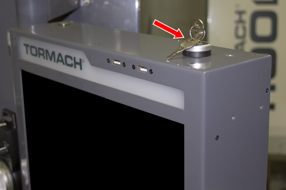
Key Use To access setup mode, you must have a key. Use the key on the top of the operator console to switch between modes.
-
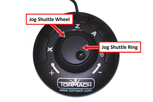
Hold-to-Run Device Use For machine motion to occur in setup mode, you must use a hold-to-run device. Hold-to-run devices include:
The button on the side of the operator console's pendant.
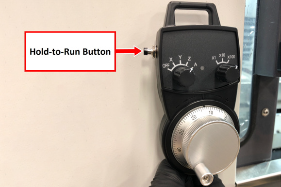
The jog shuttle wheel (the outer portion), which springs back to neutral when you release it.
-
Machine Motion Restrictions When the enclosure doors are open, and the machine is in setup mode, machine motion is restricted:
-
Maximum Feed Rate 2 m/min, on a maximum of one axis, with a hold-to-run device.
NOTE: To jog an axis with the keyboard, also use a hold-to-run device. -
Maximum Spindle Speed 700 rpm with a hold-to-run device.
-
Mode Constraints
Both operating modes restrict some machine activities while the enclosure doors are open. To understand how to use the machine with the enclosure doors open, read the following table.
NOTE: This table assumes that the enclosure door is open and stays open during each activity.
|
To ... with the Enclosure Doors Open |
In Run Mode |
In Setup Mode |
|
Move the (optional) Automatic Tool Changer (ATC) tray in or out |

|
|
|
Release a tool from the spindle |

|

|
|
Start a program |
|
|
|
Use an ATC air blast |
|
|
|
Use coolant |
|
|
|
Use a hold-to-run device to move one axis |
|
|
|
Use a hold-to-run device to move more than one axis |
|
|
|
Use a hold-to-run device to rotate the spindle less than 700 rpm |
|
|
|
Use a hold-to-run device to rotate the spindle more than 700 rpm |
|
|
Key to the symbols used in the above table:
|
Symbol |
Meaning of Symbol |
|
|
Allowed |
|
|
Not allowed |
Automatic Tool Changer (ATC) Constraints
While the enclosure doors are open, the ATC tray won't rotate, move toward the spindle, or back to its retracted position.
To load tools into the tray, do one of the following:
-
Load One Tool
-
Open the enclosure doors and put a tool in the spindle. Then, close the enclosure doors.
-
From the PathPilot interface, in the Tool DRO field, type the number of the tool that you put in the spindle in Step 1.
-
Select M6 G43.
-
On the ATC tab, select Store Current Tool.
-
Repeat Steps 1 through 4 for each tool that you want to load.
-
Load an Entire Tool Tray
-
Remove the tool from the spindle.
-
Close the enclosure doors.
-
From the PathPilot interface, on the ATC tab, select Go To Tray Load Position.
The ATC tray moves under the spindle, and the ATC door opens to the tool fork. -
Open the enclosure doors.
-
Put the tool into the tool fork.
-
On the ATC tab, in the Tool Number DRO field, type the number of the tool that you put into the tool fork in Step 5.
-
Select Insert.
-
Select Tray Fwd or Tray Rev to rotate the tray to the next open tool fork.
-
Repeat Steps 5 through 8 for each tool that you want to load.
-
Close the enclosure doors.
-
On the ATC tab, select Retract.
The ATC tray moves away from the spindle.
Looking for more information?
This is a section of the 1500MX operator's manual. To view the whole manual, go to Tormach document UM10811.
If you have additional questions, we can help. Create a support ticket with Tormach Technical Support at tormach.com/how-to-submit-a-support-ticket for guidance on how to proceed.