Purpose
This document gives instructions on installing the Full Enclosure Kit for 15L Slant-PRO Lathe.
Product Information
Product: Full Enclosure Kit for 15L Slant-PRO Lathe (PN 50610)
|
Item No. |
Part No. |
Description |
Quantity |
|
1 |
50580 |
Enclosure Panel, 15L, Left |
1 |
|
2 |
50581 |
Enclosure Panel, 15L, Top |
1 |
|
3 |
50582 |
Enclosure Panel, 15L, Back |
1 |
|
4 |
50583 |
Enclosure Panel, 15L, Right |
1 |
|
5 |
50584 |
Enclosure Panel, 15L, Front |
1 |
|
6 |
50590 |
Brush Strip, 15L |
1 |
|
7 |
37622 |
Linear Rail Support, Round, 16 mm |
4 |
|
8 |
50591 |
Linear Rail Round, 16 mm - 1013 mm |
2 |
|
9 |
37610 |
Linear Rail Block, Round, 16 mm |
4 |
|
10 |
38357 |
Bumper |
4 |
|
11 |
50592 |
Linear Bearing Spacer |
4 |
|
12 |
50593 |
Pull Handle, 120 mm, M8 |
1 |
|
13 |
50595 |
Window Retainer, 15L |
4 |
|
14 |
35120 |
10 mm Window, Polycarbonate |
1 |
|
15 |
50588 |
Door Switch Bracket, 15L Enclosure |
1 |
|
16 |
50589 |
Door Switch Trip Plate, 15L Enclosure |
1 |
|
17 |
50586 |
Enclosure Panel, 15L, Back Access |
1 |
|
18 |
50587 |
Enclosure Panel, 15L, Side Access |
1 |
|
19 |
38356 |
Window Seal Strip |
7 m |
|
20 |
50596 |
Enclosure Panel, 15L, Splash Guard |
1 |
|
21 |
38205 |
Screw, Button Head Cap, M5 × 0.8 - 10, Stainless Steel |
105 |
|
22 |
31895 |
Screw, Button Head Cap, M8 × 1.25 - 20 |
1 |
|
23 |
50578 |
Screw, Button Head Cap, M8 × 1.25 - 12 |
5 |
|
24 |
30581 |
Washer, Flat, M8, 1.4 mm |
4 |
|
25 |
37186 |
Nut, Flange, M8 × 1.25 |
1 |
|
26 |
33117 |
Screw, Socket Head Cap, M6 × 1.0 - 16 |
11 |
|
27 |
50576 |
Nut, Flange, M6 × 1.0 |
11 |
|
28 |
38734 |
Screw, Socket Head Cap, M5 × 0.8 - 16 |
4 |
|
29 |
50577 |
Nut, Flange, M5 × 0.8 |
17 |
|
30 |
31460 |
Cable Tie Anchor, M5 |
9 |
|
31 |
31719 |
Cable Tie, 4 in. Nylon, Black (100 mm) |
5 |
|
32 |
32791 |
Cable Tie, 7.5 in. Nylon, Black (200 mm) |
4 |
|
33 |
50594 |
Roll 36 mm × 5 mm Adhesive Backed Foam Tape |
2 m |
|
34 |
50597 |
8.5 mm Drill Bit |
1 |
|
35 |
50585 |
Door |
1 |
NOTE: If any items are missing, we can help. Create a support ticket with Tormach Technical Support at tormach.com/how-to-submit-a-support-ticket for guidance on how to proceed.
Required Tools
This procedure requires the following tools. Collect them before you begin.
-
Marker or pencil
-
Metric hex wrench set
-
Phillips screwdriver
-
Shears
Install the Enclosure
Complete the following steps in the order listed:
Remove the Belt Guard Cover
-
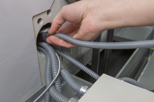
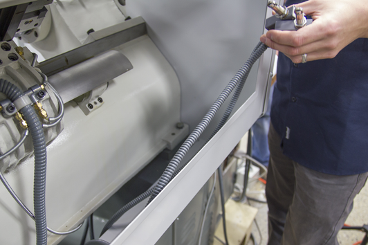
Route the door switch cables through the base casting of the lathe (to the left of the belt guard cover).
-
Continue to route the door switch cables under the lathe casting and toward the front of the machine.
-
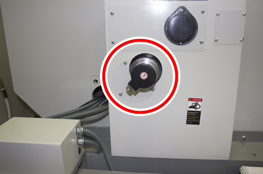
Identify the rotary encoder on the belt guard cover.
-
Disconnect the power connector from the rotary encoder.
-
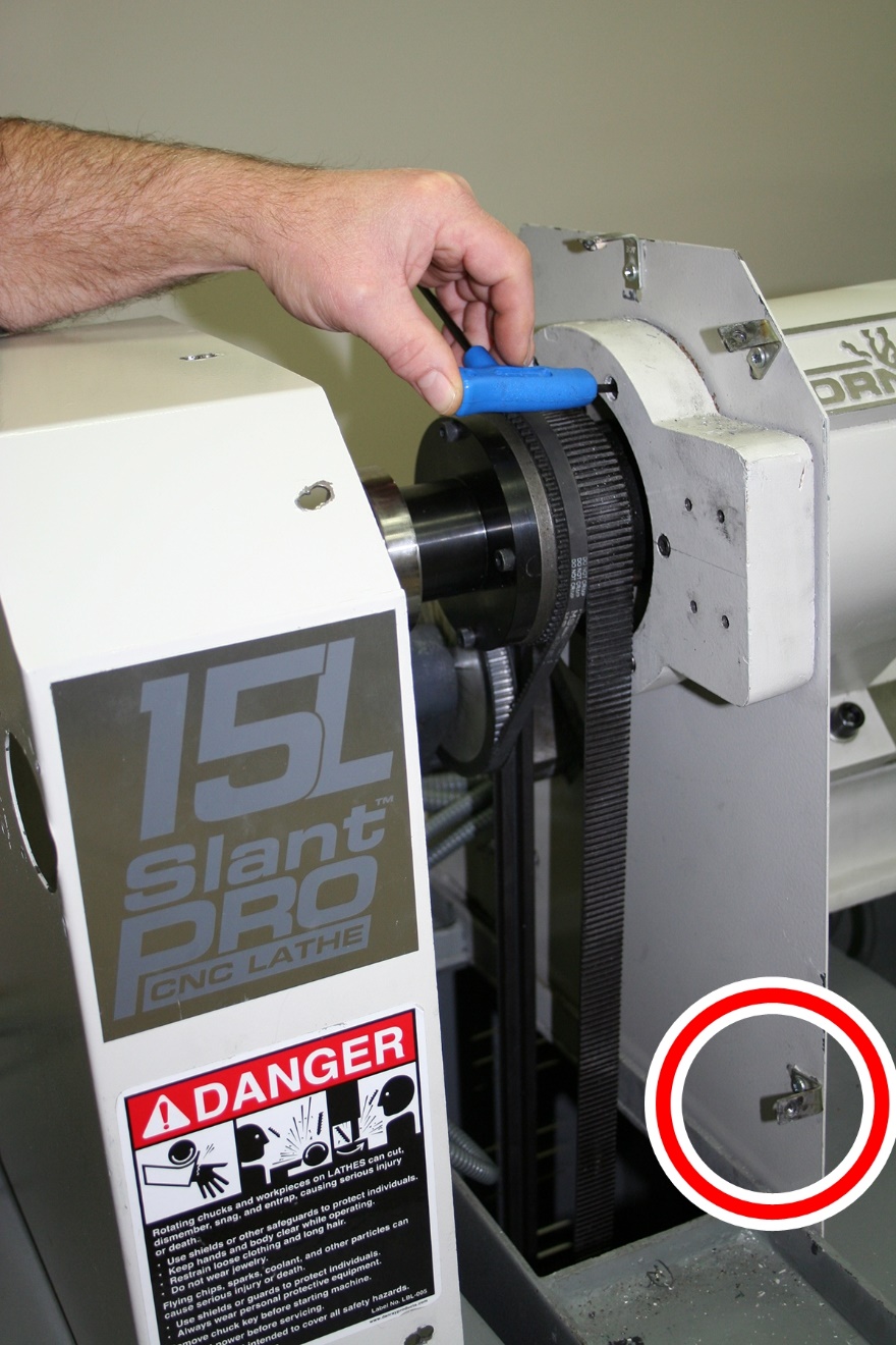
Remove the five screws that secure the belt guard cover to the machine with a Phillips screwdriver, and set aside the belt guard cover and its screws.
-
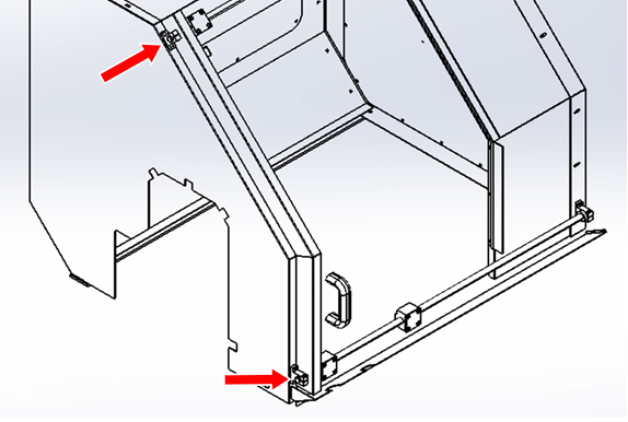
Identify the five belt guard cover mounting brackets. Then, loosen the top three brackets and the lower left bracket with a Phillips screwdriver, and remove and set aside the lower right bracket and its screws. The bracket that's completely removed is shown in the following image.
-
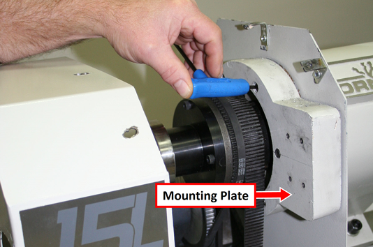
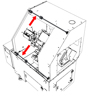
Loosen the six socket head cap screws on the mounting plate with a 5 mm hex wrench.
-
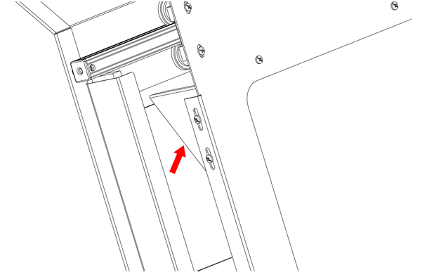
Move the mounting plate to the left (away from the headstock). In the next section, you'll install the left side panel between it and the sheet metal guard, as shown in the following image.
Install the Enclosure Panels
Tip! We recommend leaving the screws loose while you install the enclosure panels. This way, it's easier to align the panels throughout the procedure.
-
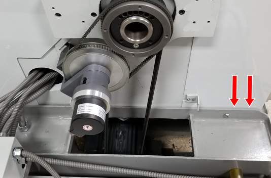
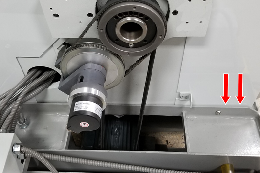
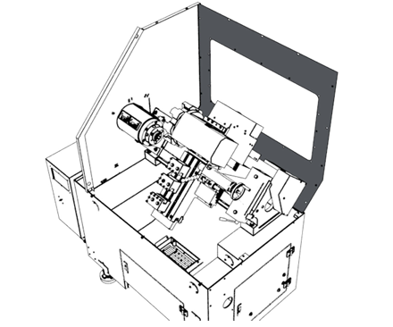
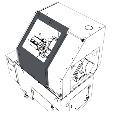
Slide the left side panel over the spindle so that it's between the mounting plate and the sheet metal guard.
-
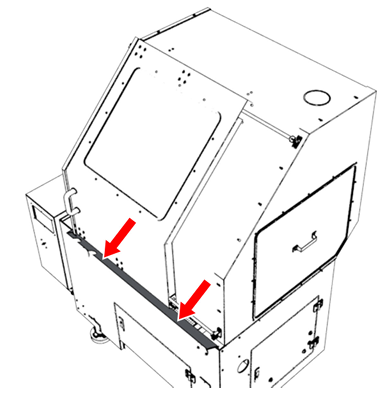
Verify that the panel is on the inside of the stand as shown in the following image.
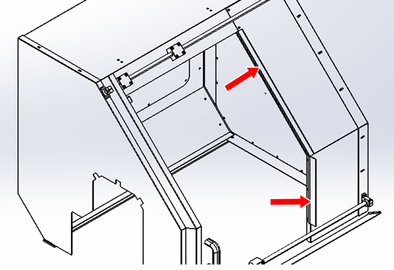
-
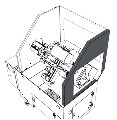
Put the rear panel on the back of the stand so that the end of the panel is inside of the left side panel. Attach the rear panel to the left side panel with four M5 screws and a 3 mm hex wrench.
-
Put the right side panel on the right end of the stand so that the rear panel is inside of the right side panel. Attach the right side panel to the rear panel with six M5 screws and a 3 mm hex wrench.
-
Measure and cut a strip of adhesive-backed foam to fit the bottom of the rear and right side enclosure panels.
-
Align the foam that you cut in Step 5 to the bottom flanges of the panels, and use a marker or pencil to put a mark on each of the panels' hole locations.
-
Cut a notch or hole into the marks in the foam, which allows screws to pass through the foam and secure the enclosure to the stand later in this procedure.
Tip! You may need to loosen some of the screws, or temporarily remove the panels, to attach the foam in the next step.
-
Remove the backing from the foam and attach it to the bottom flanges of the panels. Ensure that the hole locations in the foam align with the hole locations on the panels.
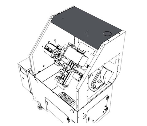
NOTE: Attaching the top panel is easier to do with a helper. We recommend that at least two people complete the next step together.
-
Put the top panel between the side panels so that it's inside of the side panels' flange. Attach the top panel to the side panels and the rear panel with five M5 screws and a 3 mm hex wrench.
-
Put the front right panel on the inside of the right side panel. Attach the front right panel to the right side panel and the top panel with six M5 screws and a 3 mm hex wrench.
-
Secure the enclosure to the machine stand with three M8 × 25 - 12 button head cap screws.

-
Secure the left side panel to the machine stand with an M8 × 1.25 - 20 button head cap screw, an M8 nut, and a washer.
Install and Align the Door
-
Attach two of the linear rail supports to the left side panel with four M5 screws and a 3 mm hex wrench.
-
Slide two linear bearings onto both door rails, and then slide one bumper onto each end of both door rails.
-
Insert the left end of one linear door rail assembly into the top linear rail support on the left side panel. Then, attach it to the right side panel using the remaining linear rail support with two M5 screws and a 3 mm hex wrench.
-
Repeat Step 3 for the bottom linear door rail.
-
Put one door spacer on top of each linear block on the upper door rail. Then, attach the door onto the linear blocks with eight M5 button head cap screws.
-
Repeat Step 5 to secure the bottom of the door to the linear blocks on the bottom door rail.
-
Install the door handle to the front of the door with two M8 button head cap screws.
-
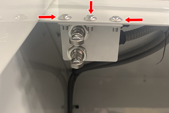
Install the door switch mounting bracket with three M5 screws as shown in the following image. Verify that the bracket is mounted so that the screws are below the flange. If they're not, the screws interfere with the door switches.
-
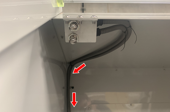
Route the door switch cables through the machine, and secure them in place with cable ties, cable tie holders, and M5 screws. Verify that the cables are routed in the direction shown in the following image.
-
Install the door switch trip bracket on the left side of the door with two M5 screws and a 3 mm hex wrench.
-
Align the door rails:
-
Loosen the two mounting screws that secure the upper left linear rail support to the enclosure panel.
-
Slide the door closed, and then re-tighten the M5 screws on the upper left linear rail support with a 3 mm hex wrench.
-
Open and close the door to test for smooth motion. If the door doesn't move smoothly, repeat Step 11 to adjust the remaining three linear rail supports.
-
-
Adjust the door switch trip plate:
-
Observe the door switches as you slide the door closed. Both switches should engage as they contact the door switch trip plate, and they should click at the same time. If they don't, do one of the following:
-
Loosen the door switch trip plate and adjust it up or down. Then, repeat Step A.
-
Loosen the mounting nuts on one of the door switches, and adjust the switch up or down so that both switches are at the same height. Then, repeat Step A.
-
-
Install Remaining Enclosure Components
-
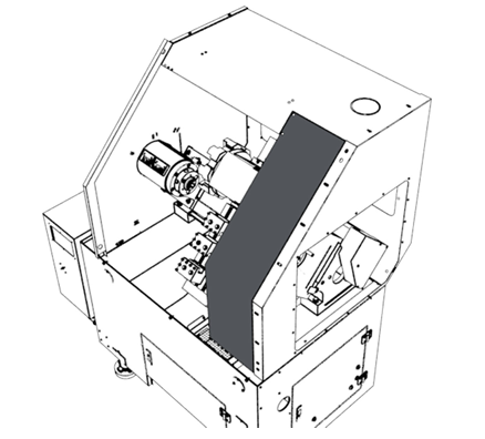
Push the rubber window seal stripping onto the openings for both access panels (on the left side panel and on the rear panel) and onto the opening for the door window.
-
Attach the access panels to the inside of both the left side panel and the rear panel with M5 screws and a 3 mm hex wrench.
-
Install the rear and left window retainers on the inside of the door.
-
From the right side of the door, slide the window into the two window retainers that you installed in Step 3.
-
Install the top and right window retainers to secure the window onto the door.
-
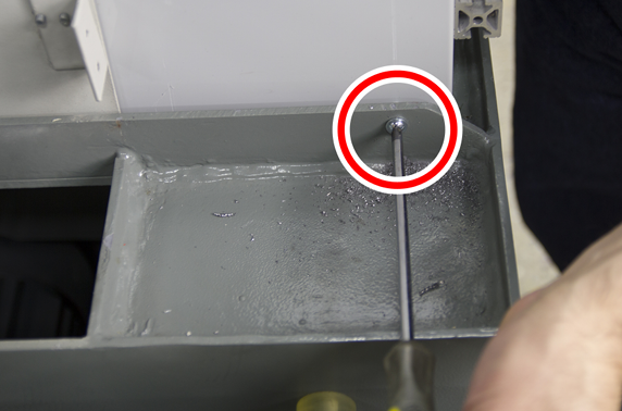
Install the front drip tray to the inside of the machine stand with three M6 × 1 - 16 socket head cap screws, nuts, and washers.
-
Install the door brush to the left side of the front right panel with M5 screws and a 3 mm hex wrench.
Re-Install the Belt Guard Cover
-
Reattach the spindle mounting bracket screws, that you set aside earlier, with a Phillips screwdriver.
-
Reattach the belt guard cover with the screws that you set aside earlier and a Phillips screwdriver.
-
Reconnect the power connector to the rotary encoder.
Verify the Installation
-
Power on the machine and the PathPilot controller.
-
Turn the Main Disconnect switch to ON on the side of the electrical cabinet.
-
Twist out the machine's red Emergency Stop button, which enables movement to the machine axes and the spindle.
-
Press the Start button.
-
Bring the machine out of reset and reference it.
-
-
From the PathPilot interface, go to the Status tab.
-
Identify the Guard/Door Switch LED light. Observe the light as you:
-
Open the door. Verify that the light is off.
-
Close the door. Verify that the light is on.
If the light didn't function as described, you must readjust the door switches or the door switch trip plate. Go to "Install and Align the Door".
-
To view a PDF version of your manual, go to Tormach document TD10773.
If you have additional questions, we can help. Create a support ticket with Tormach Technical Support at tormach.com/how-to-submit-a-support-ticket for guidance on how to proceed.