Product Information
Products:
|
Qty |
3-Jaw Reversible 6 in. Lathe Chuck 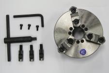
|
4-Jaw Independent Reversible 6 in. Lathe Chuck 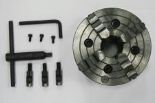
|
6 in. Face Plate 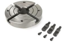
|
|
1 |
3-Jaw Chuck |
4-Jaw Chuck |
6 in. Face Plate |
|
1 |
Chuck Key |
Chuck Key |
— |
|
1 |
Hex Wrench |
Hex Wrench |
— |
|
3 |
Retention Stud |
Retention Stud |
Retention Stud |
|
3 |
5 mm Socket Head Cap Screw |
5 mm Socket Head Cap Screw |
5 mm Socket Head Cap Screw |
NOTE: If any items are missing, we can help. Create a support ticket with Tormach Technical Support at tormach.com/how-to-submit-a-support-ticket for guidance on how to proceed.
Install the Chuck
-
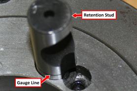
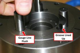
Screw the three retention studs into the back of the chuck. The studs are properly installed when the gauge line, as shown in the following image, is flush with the chuck.
-
Make sure the groove in the side of each retention stud is lined up with the matching counter bore, as shown in the following image.
-
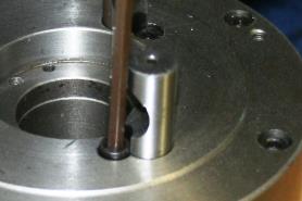
To lock the retention studs in the correct position, use the 5 mm hex wrench to tighten each stud with a provided socket head cap screw.
-
Press the Emergency Stop button to disable the spindle.
-
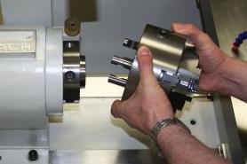
Install the chuck, ensuring that the retention studs are lined up with the corresponding cam holes.
Lock the Chuck
WARNING! Ejection Hazard: Before operating the spindle, you must verify that the chuck is tightly locked in position and that the chuck key is removed. If you don't, the chuck or the chuck key could be ejected from the machine, causing death or serious injury.
-
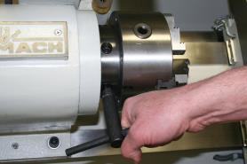
To lock the chuck, insert the provided chuck key into the cam lock.
-
Turn each cam lock clockwise until the witness mark lands between the 3 o’clock and 6 o’clock positions.
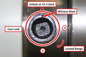
NOTE: If the cam lock doesn't turn as detailed, go to "Troubleshooting".
Unlock the Chuck
-
Press the Emergency Stop button to disable the spindle.
-
Use the chuck key to turn each cam lock counter clockwise until the witness mark lands at the 12 o’clock position.
-
Remove the chuck with two hands.
Troubleshooting
|
Problem: The cam lock witness mark rotates past the 6 o’clock position |
|
|
Cause |
How-To Steps |
|
The retention stud has not been screwed in far enough. |
Unlock the three cams and remove the chuck. Remove the socket head cap screw on the retention stud in question. Rotate the stud clockwise one revolution. Re-tighten the retention stud’s socket head cap screw and reinstall the chuck. |
|
Problem: The cam lock witness mark does not rotate past the 3 o’clock position |
|
|
Cause |
How-To Steps |
|
The retention stud has been screwed in too far. |
Unlock the three cams and remove the chuck. Remove the socket head cap screw on the retention stud in question. Rotate the stud counter clockwise one revolution. re-tighten the retention stud’s socket head cap screw and reinstall the chuck. |
To view a PDF version of your manual, go to Tormach document TD10245.
If you have additional questions, we can help. Create a support ticket with Tormach Technical Support at tormach.com/how-to-submit-a-support-ticket for guidance on how to proceed.