Purpose
This document gives instructions on installing and using the Quick Change Tool Post Kit on a 15L Slant-PRO lathe.
Product Information
Product: Quick Change Tool Post Kit for 15L Slant-PRO (PN 33272)
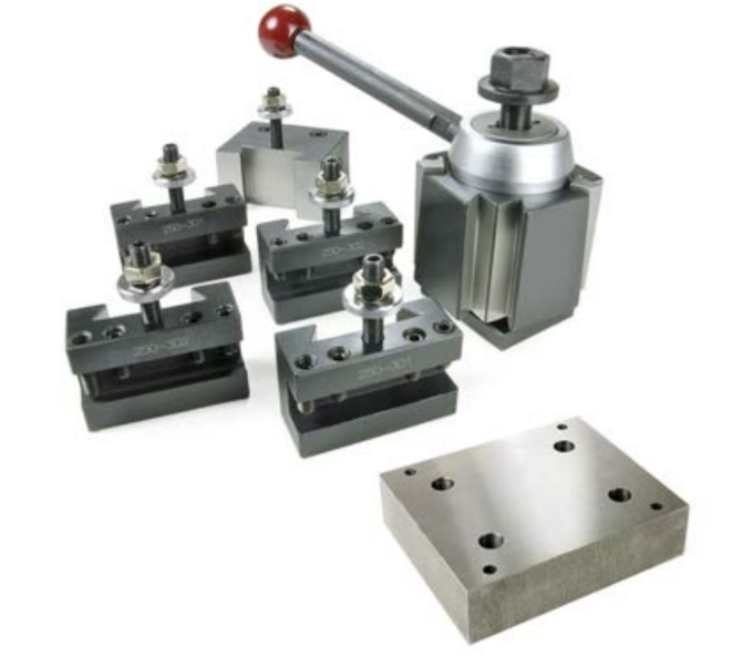
|
Quantity |
Description |
Size |
|
4 |
M8 × 40 mm Socket Head Screw |
— |
|
2 |
#1 Tool Holder for Quick Change Post (PN 33123) |
CXA |
|
2 |
#2 Tool Holder for Quick Change Post (PN 33124) |
CXA |
|
1 |
#4 Tool Holder for Quick Change Post (PN 33125) |
CXA |
|
1 |
Tool Post Handle |
— |
|
1 |
Quick Change Tool Mount Plate (33202) |
— |
|
1 |
Quick Change Tool Post (PN 34129) |
CXA |
NOTE: If any items are missing, we can help. Create a support ticket with Tormach Technical Support at tormach.com/how-to-submit-a-support-ticket for guidance on how to proceed.
Required Tools
This procedure requires the following tools. Collect them before you begin.
-
Adjustable wrench
-
Dead-blow hammer
-
Magnetic dial test indicator
-
Metric hex wrench set
-
Rust preventative
Install the Mounting Plate and Quick Change Tool Holder
-
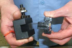
Remove the mounting block from the bottom of the tool post, and discard it.
-
Examine the surface of the machine's carriage and the mounting plate for burrs, grit, or dirt. If necessary, use a machinist's stone to remove any burrs. Then, use a rust preventative (like WD40® or similar) on the surfaces.
-
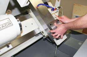
Attach the mounting plate to the machine's carriage with four M8 × 40 mm socket head cap screws.
-
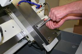
Put the tool post stud into the mounting plate, and securely tighten it.
-
Move the tool post over the tool post stud.
-
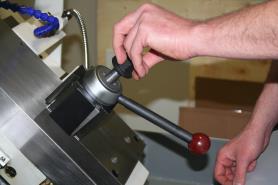
Put the tool post handle into the tool post, and securely tighten it.
-
Put the nut on the tool post stud, and hand-tighten it.
Install the Tool into the Quick Change Tool Holder
-
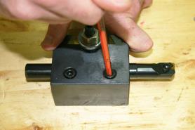
Find a tool and its equivalent tool holder, and put the tool into the tool holder.
-
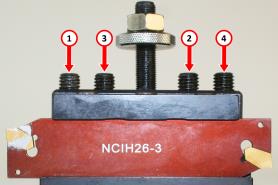
Lock the tool into the tool holder: with the tool pointing toward you, tighten the hex head screws in the order shown in the following image.
-
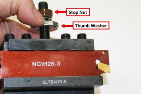
Set the rough tool height by adjusting the thumb screw. Then, secure it in place with the stop nut. You'll make fine adjustments later in this procedure to bring the tool plane on center with the spindle.
-
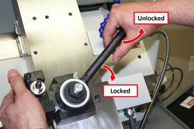
To attach the tool holder, the tool post must be in the unlocked position: move the tool post handle up.
-
Put the tool holder onto the tool post, and then move the tool post handle down to the locked position.
-
Before operating the machine, you must make sure that the quick change tool holder is aligned. Go to "Align the Tool".
To Use a Boring Bar
-
To attach the tool holder, the tool post must be in the unlocked position: move the tool post handle up.
-
Put the tool into the boring bar holder.
NOTE: The reducer sleeve (3/4-in.-1-in.) inside the boring bar holder is included.
-
Lock the tool into the tool holder: tighten its two hex head screws.
Tip! When you remove the tool, loosen the hex head screws, and gently tap them with a dead-blow hammer.
-
Put the tool holder onto the tool post, and then move the tool post handle down to the locked position.

Align the Tool
-
Power on the machine and the PathPilot controller.
-
Turn the Main Disconnect switch to ON on the side of the electrical cabinet.
-
Twist out the machine's red Emergency Stop button, which enables movement to the machine axes and the spindle.
-
Press the Reset button.
-
Bring the machine out of reset and reference it.
-
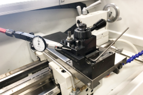
-
Attach a magnetic dial test indicator to the spindle.
-
Put the indicator tip on the face of the tool holder.
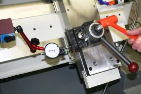
-
Slowly jog the machine along the X-axis to move the indicator tip along the face of the tool.
-
Adjust the quick change tool post alignment as necessary: use a dead-blow hammer to tap the tool post, and then repeat Steps 4 through 5.
-
Securely tighten the tool post nut with an adjustable wrench.
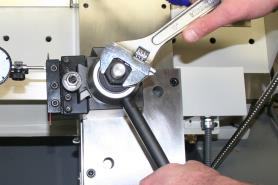
-
Repeat Steps 4 through 5 to make sure that the tool post is still correctly aligned after tightening the tool post nut.
To view a PDF version of your manual, go to Tormach document TD10246.
If you have additional questions, we can help. Create a support ticket with Tormach Technical Support at tormach.com/how-to-submit-a-support-ticket for guidance on how to proceed.