Uncrating
![]()
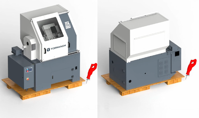
The 15L Slant-PRO is shipped on a standard pallet and can be off-loaded from a truck with a tailgate lift and moved to the desired install location with a hydraulic pallet jack.
![]()
-
Use strap snips and a small pry bar to open and disassemble shipping crate. Remove top of crate first, followed by four sides.
-
Remove and discard the plastic packaging from the machine.
Shipping Damage or Shortages
Once received, inspect and note any shipping damage that may have occurred during transit. Also check received goods against packing list. Any damage claims or shortages must be addressed within 30 days of receipt.
Remove Machine from Pallet
![]()
Lathe Lift Kit
The preferred method of lifting the lathe is using the Lathe Lift Kit (PN 33269) to raise the machine with four temporary legs and jack screws.
NOTE: Before separating the lathe from the pallet, ensure there is enough space on the sides of the lathe to slide the pallet out from underneath it. If walls or immoveable objects are in the way, a different location may be required.
-
Cut a strip of wood down the entire length of the pallet, on both the front and the back side, to provide clearance for the lifting feet. A skill saw works well for this (see Figure 1).
-
Tape the electrical cabinet door shut to prevent it from swinging open during the lift procedure.
-
Open the coolant tank door on the front of the lathe and temporarily slide it off of the shipping pallet.
NOTE: Do not remove the pallet out before removing the Coolant Tank. Failure to do so could result in machine damage.
-
Cut the shipping straps the secure the emergency stop box and power cable to the pallet.
-
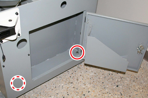
Four pallet bolts are used to temporarily attach the pallet to the lathe; identify two right-hand bolts located inside the controller cabinet (see Figure 2).
-
Loosen and remove nuts and washers from two bolts inside the controller cabinet.
-
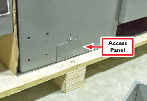
Identify two small Access Panels on left side of lathe (see Figure 3).
-
Using a Phillips screwdriver, remove Access Panels; set aside.
-
Loosen and remove nuts and washers from two bolts inside the Access Panels.
-
Using four M8 x 20 mm Socket Head Cap Screws and four M8 Flat Washers, attach one Lifting Foot to each of the four corner attachment sites (see Figure 4); securely tighten.
-
Slide a Lifting Pad underneath each of the four installed Lifting Feet; align hole on Lifting Pad with Lifting Foot’s bolt hole (see Figure 5).
-
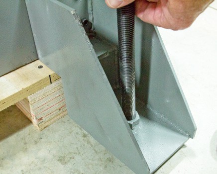
Attach one M20 x 250 mm Threaded Rod through each Lifting Foot and into its Lifting Pad (see Figure 6).
-
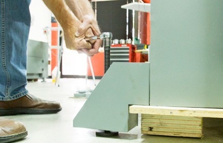
Using a socket wrench, gradually adjust each Lifting Foot to raise the lathe evenly until lathe is clear of the floor (see Figure 7).
-
Slide the pallet from underneath the lathe.
-
Depending on the accessories that you’re going to install on your lathe, do one of the following:
-
Installing a Turret: Keep the lifting feet on the lathe for the turret installation procedure. When finished installing the turret, go to Attach Lathe Feet.
-
No Turret: Go to Attach Lathe Feet.
-
Attach Lathe Feet
-
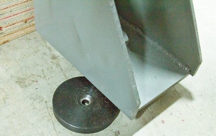
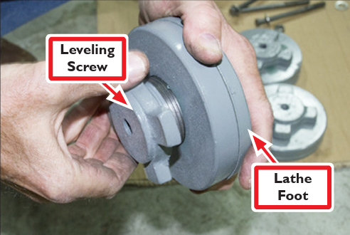
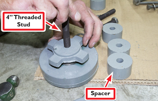
Unscrew Leveling Screw on each Lathe Foot until close to full height (see Figure 8); apply a dab of grease on threads.
-
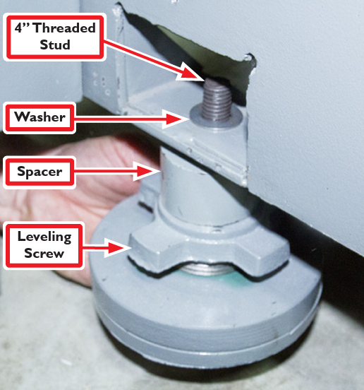
Screw one 4” Threaded Stud into each Lathe Foot (see Figure 9); slide a Spacer onto each stud.
-
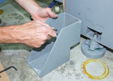
Insert each lathe foot assembly into base of lathe via a lag bolt hole (see Figure 10). Slip a Washer onto each Threaded Stud and secure feet tightly with nuts.
NOTE: Lifting Feet are not intended to support the lathe during operation.
-
Reattach two Access Panels set aside earlier.
-
When the lathe is completely supported by four lathe feet, lower four M20 x 250 mm Threaded Rods in stages until the lathe rests on its feet; remove rods.
-
Unscrew and remove four M8 x 20 Socket Head Cap Screws and M8 Washers securing each Lifting Foot to the lathe; remove four Lifting Feet from lathe.
Looking for more information?
This is a section of the 15L operator's manual. To view the whole manual, go to Tormach document UM10225.
If you have additional questions, we can help. Create a support ticket with Tormach Technical Support at tormach.com/how-to-submit-a-support-ticket for guidance on how to proceed.