Background
Each machine is tuned at the factory to meet or exceed certain precision metrics. These metrics are indicated on the Certificate of Inspection that is included with each mill, along with the actual values measured for each metric as part of Tormach’s Quality Assurance program. The following advanced maintenance procedures may become necessary over the ownership lifetime to maintain the original factory precision:
-
Gib adjustment
-
Angular contact bearing preload adjustment
-
Geometry adjustment (tram)
These adjustments are generally used to address component wear-in over time, but may also be needed to correct misalignment resulting from misuse, a hard crash of the system, or when some components are removed or replaced due to damage. The frequency of these procedures depends on both how the mill is used and how often.
Over time, the dovetail ways and gibs wear from sliding friction and it may be necessary to tighten the gib to reduce axis backlash. To compensate for wear, the design of a dovetail-gibbed way allows for the position of the gib to be adjusted to maintain an appropriate sliding clearance.
A properly adjusted gib minimizes lost motion by balancing conventional backlash and sliding friction. A gib that is too loose results in excessive conventional backlash; a gib that is too tight cannot adequately support an oil film resulting in excessive sliding friction. The position of the tapered gib plate is controlled by two screws on either end of the gib that capture the position of the gib with respect to the saddle. These screws can be adjusted (as a pair) to tune the tightness and sliding friction of the dovetail way for each axis.
Definitions
The following definitions are important to the advanced maintenance discussion.
Lost motion: the difference between commanded motion and observed motion. This is sometimes referred to as apparent backlash. There are a number of components of lost motion, including conventional backlash, bearing compressibility, sliding friction, and thermal expansion.
Backlash: the major component of lost motion in a machine tool axis. It results from the clearance between moving mechanisms. This is sometimes referred to as play. There are two sources of conventional backlash that can be adjusted on the PCNC:
-
Space between gib and way needed to support an oil film. This is tuned by tightening the gib.
-
The space between the ball bearings and races in the angular contact bearing pair that supports the ball screw. This is tuned by increasing the angular contact bearing pair preload.
Tools
-
Flat-bladed screwdriver
-
Dial Indicator (.0005” resolution)
-
Magnetic Base
-
Metric allen keys
Measuring Lost Motion
Correctly measuring lost motion is critical to successfully undertaking any of advanced maintenance procedures detailed in the following sections. Mill setup and tuning is done under no-load conditions. The precision measurements recorded in the Tormach Certificate of Inspection are taken under no-load conditions. The accuracy of a machined feature is not an indicator of machine precision. Tool flex, workpiece flex, fixture flex, thermal expansion, and other factors contribute to the overall machined-part accuracy.
The following method describes the proper procedure to measure X-axis backlash. An analogous procedure is used to measure Y- and Z-axis backlash.
-
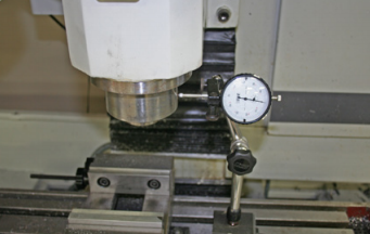
Mount a dial indicator to the mill table along the X-axis to the left of the spindle, with the tip pointing at the spindle.
-
Jog the Y- and Z-axis to position the spindle head so the indictor tip contacts the outer diameter of the spindle cartridge (see Figure 9.1).
-
Carefully jog the X-axis in the positive direction until the indictor contacts the spindle. After initial contact, continue to jog the X-axis in the positive direction so that the dial makes at least one complete revolution; stop when dial reads 0.
-
Zero the X DRO field in PathPilot
-
In MDI field, program a positive X move of .01” at a feed rate of 5 IPM: G01 X.01 F5. The spindle head moves slightly in +X direction. When finished, indictor should read .010”.
-
Program an X move back to 0: G01 X0 F5. The spindle head moves slightly in the -X direction. The X DRO should say 0; however, the dial indicator should read a number very close to 0. This value is the measured lost motion.
Gib Adjustment
The recommended method for gib adjustment is to measure axis lost motion while incrementally tightening the gibs to arrive at the correct setting. The following procedure describes this method for the Z-axis. A similar procure can be used to adjust the X-axis and Y-axis gibs; however, it should be noted that the X- and Y-axis gib adjustments cannot be considered in isolation. Tightening or loosening a gib on either axis also has an effect on the opposing axis.
The gib tightening adjustment procedure for each linear axis is detailed in the table below.
|
Gib Location |
Direction to tighten |
Notes |
|---|---|---|
|
X Axis |
Left screw CCW/Right screw CW |
|
|
Y Axis |
Front screw CW/Rear screw CCW |
Remove front and rear way covers to access gib screws |
|
Z Axis |
Upper screw CW/Lower screw CCW |
Support spindle head with a wooden block on table |
-
Loosen the upper gib screw eight rotations and tighten the lower gib screw eight rotations. This ensures that the gib clearance is quite loose.
-
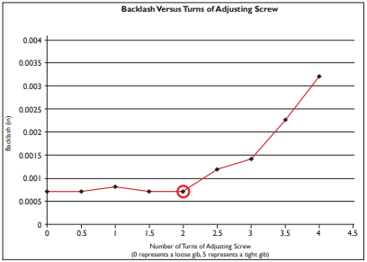
Use a dial indicator to measure lost motion in the Z-axis (refer to Lost Motion Testing). With a very loose gib, the majority of the measured lost motion is attributable to the backlash in the angular contact bearing pair. On a new mill, this value measured should be less than 0.0015” on the Z-axis and less than .0013” on X- and Y-axis.
-
Tighten the gib by one turn by loosening the lower screw first, then tightening the upper screw. Measure the backlash again.
-
Repeat this procedure until the measured backlash begins to increase. At this point, the gib setting is slightly too tight.
-
Back the adjustment off to the point just before you saw the increased backlash. That is the ideal setting for the axis.
IMPORTANT! Ensure both adjustment screws are tight after any gib adjustment. Failure to do so will result in gib movement.
Angular Contact Bearing Adjustment
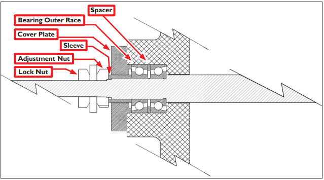
Improper ball screw bearing preload will result in either excessive backlash in the mill if it is too loose, or rapid wear and excessive friction if it is too tight. It should be noted that if your ball screw, ball nut, or angular contact bearings are worn, or if your gibs are adjusted too tight, you will not achieve appropriate lost motion values.
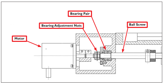
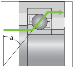
The figure below shows how the force of preload is transmitted through the bearings, from the inner race to the outer race. In a preload pair, this force is then transmitted back to the inner race by an opposed bearing. It should be apparent that the correct orientation of the angular contact bearing is critical to the operation.
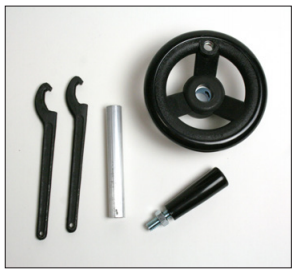
To adjust the angular contact bearing pair preload on all 770 and 1100 machines, the AC bearing service tool kit is required (part number 35355).
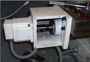
To properly estimate the torque needed to overcome angular contact bearing friction, the bearings must be isolated from the motor detent torque. The following procedure illustrates the X axes; other axes will follow suit:
-
For adjusting the X-axis, position the table near the right hand end of its travel (i.e., X near to zero). This ensures that the bearing is near to the ball nut to minimize bending of the screw during tests.
-
Remove X-axis motor mount cover plate.
-
Loosen two screws clamping the coupling between the stepper motor shaft and ball screw end.
-
Remove four cap screws holding the axis motor to the motor mount and remove axis motor. Take care not to put any strain on the motor wires.
-
Insert a 1/2” diameter rod (included in AC Bearing Service Tool Kit, PN 35355) or drill blank into the coupling. This will effectively extend the ball screw shaft outside of the motor mount.
-
Clamp a handwheel or vise grip on the end of the rod; this allows sensitive feel for the torque caused by the preload on the bearings. Rotation should be smooth with a small perceptible drag; this corresponds to a medium preload of about 150 pounds. If the rotation feels tight, you have too much preload and will dramatically shorten the life of the bearings. If the rotation is free, you have little or no preload and backlash will be excessive. This test should be done with the lock nut tight.
-
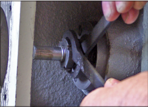
Using kit’s spanner wrenches, loosen the lock nut and back it off about two turns. Then hold the ball screw to prevent it from rotating with a pair of pliers on the coupling and tighten the adjustment nut until there is slightly more backlash than you ultimately want to achieve. Tightening the lock nut will slightly increase the bearing preload.
-
Re-mount box and motor; ensure that coupling is symmetrically fitted to the motor shaft and the screw end and is fully tightened.
Backlash Compensation
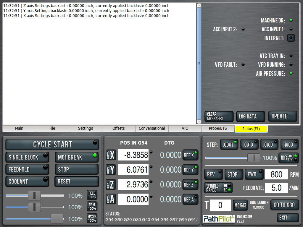
Backlash compensation is only available on Pathpilot version 2.2 and above for all machines
Backlash compensation is used after the gib and angular contact bearings have been adjusted to less than .001” of lost motion.
Use the “ADMIN SET_AXIS_BACKLASH” command in the MDI line to apply backlash compensation. Use X/Y/Z following the command to indicate the axis to apply backlash compensation to and a number following the axis to indicate the amount of compensation to apply. Compensation is limited to .005” per axis.
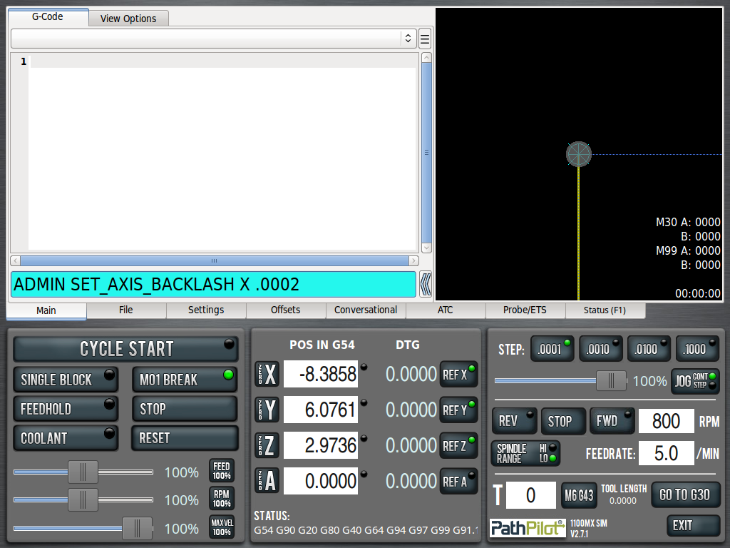
The “ADMIN GET_AXIS_BACKLASH” command will display the current amount of backlash for each axis. The “ADMIN RESET_AXIS_BACKLASH” command will reset the backlash values of all axes to 0.
