In This Section, You'll Learn:
About the basic operations required for most projects, organized as a suggested project workflow.
Start the Machine
Power on the machine and the PathPilot controller.
-
Turn the Main Disconnect switch to ON on the side of the electrical cabinet.
-
Twist out the machine's red Emergency Stop button, which enables movement to the machine axes and the spindle.
-
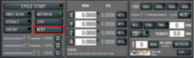
Press the Reset button.
Bring the Machine Out of Reset
Select Reset.
For more information on reset mode, see "About Reset Mode".
About Reset Mode
When the machine is first powered on, or after an emergency stop, the Reset button flashes. When you select the flashing Reset button, PathPilot verifies communication to the machine and does the following activities:
-
Brings the machine out of an emergency stop condition
-
Clears alarms
-
Clears the tool path backplot
-
Resets all modal G-codes to their normal state
-
Rewinds the currently loaded G-code program
-
Stops machine motion, but is not a replacement for the Emergency Stop button
You can select the Reset button any time while the machine is on.
Reference the Machine
-
Verify that the machine can freely move to its reference position (at the ends of travel).
-
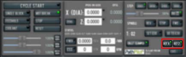
To verify that the tooling is clear of any possible obstructions, reference the Z-axis before referencing the other axes: from the PathPilot interface, select Ref Z.
-
Once the spindle is clear of any possible obstructions, continue referencing all axes.
NOTE: You can select the buttons one after another. Once the machine references one axis, it'll move on to the next.
After each axis is referenced, its button light comes on.
For more information on referencing the machine, see "About Referencing".
About Referencing
You must reference the machine to establish a known position for PathPilot. The position that's set while referencing the machine is the origin of the machine coordinate system. Without referencing the machine, PathPilot won't know the current position of the machine axes.
You must reference the machine at the following times:
-
After you power on the machine
-
After you push in the Emergency Stop button
-
Before running a G-code program
-
Before using MDI commands
-
Before setting work or tool offsets
-
After a collision or an axis stall/fault
When referencing, the machine moves each axis to the end of its travel. The machine stops at the limit switch, which sets the axis’ reference position.
Jog the Machine
To switch between jogging modes:
-
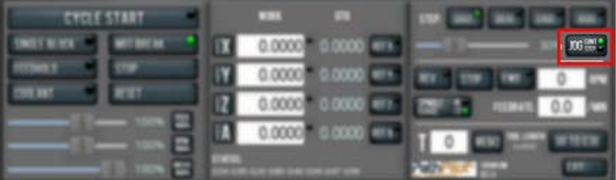
From the Manual Control area, in the Jog group, select Jog.
PathPilot toggles between continuous velocity mode and step mode.
-
When the Cont green light is on, continuous velocity mode is selected.
-
When the Step green light is on, step mode is selected.
To use continuous velocity mode:
-
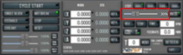
Set the velocity: drag the Jog Speed slider.
For more information on continuous velocity mode, see "About Continuous Velocity Jogging".
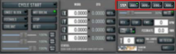
To use step mode, select the step size. Do one of the following, depending on your accessories:
-
In the Manual Control Area, in the Jog group, select the step size.
The Step button's light comes on, indicating which step size is active.
-
On the (optional) Jog Shuttle, press the Step button to toggle the currently selected step size.
In the PathPilot interface, the Step button's light comes on, indicating which step size is active.
For more information on step mode, see "About Step Jogging" (page 4).
About Jogging
Jogging is the operation of manually moving an axis in various directions (like to set up and indicate fixtures or workpieces). You can't manually jog the machine while it's performing automatic operations (like running a G-code program or an MDI command).
Jog the machine using the keyboard, the optional Jog Shuttle or Operator Console Pendant. Whichever device you're jogging with, you can either:
-
Jog the machine at a consistent velocity (for information, see "About Continuous Velocity Jogging").
-
Jog the machine in steps (for information, see "About Step Jogging").
For more information, see "Jog Controls Reference".
About Continuous Velocity Jogging
While jogging in continuous velocity mode, the machine moves at a constant speed for as long as:
-
A keyboard key is pressed
-
The Jog Shuttle outer ring is twisted away from the neutral position
-
The Operator Console Pendent wheel is turned in the desired direction.
This is useful when you're doing things like:
-
Roughly positioning the machine (for example, to move the spindle head away from the workpiece).
-
Moving the machine a certain distance at a constant speed.
About Step Jogging
While jogging in step mode, the machine moves one step each time you either press a jog key on the keyboard, click the inner wheel of the Jog Shuttle, or rotate the Console Pendant one click. The jog step sizes range depending on the programming mode you are using:
-
Imperial (G20) Mode 0.0001 in. to 0.1000 in.
-
Metric (G21) Mode 0.01 mm to 10 mm
Step jogging mode is useful to finely move the machine, like when you're indicating a workpiece or manually setting tool lengths.
The jog keys on the keyboard only move the machine in steps when step mode is indicated in PathPilot. The inner wheel on the jog shuttle always moves the machine in steps, regardless of which mode is indicated in PathPilot.
Jog Controls Reference
The machine’s jogging functions are controlled by the following:
-
The Jog group of the Manual Control area in the PathPilot interface
-
The keyboard
-
The (optional) Jog Shuttle
-
The (optional) Operator Console Pendant
|
Axis |
Direction |
Keyboard Key |
Jog Shuttle |
|
X-Axis |
Positive |
Up Arrow |
Clockwise |
|
Negative |
Down Arrow |
Counterclockwise |
|
|
Z-Axis |
Positive |
Right Arrow |
Clockwise |
|
Negative |
Left Arrow |
Counterclockwise |
Jogging in PathPilot
From the PathPilot interface, in the Manual Control area, the Jog group has the following functions:
-
The Jog button, which toggles between continuous velocity mode and step mode.
-
The Jog Speed slider, which controls the machine’s jog rate (whether in continuous velocity mode or in step mode).
The jog rate is measured as a percentage of the machine's maximum jog rate.
Jogging with the Keyboard
Pressing the keys results in the following actions:
-
[KEY] jogs the axis at the current jog rate.
-
[KEY]+Shift jogs the axis at the maximum jog rate.
Jogging with the Optional Jog Shuttle or Operator Console Pendant
Both the Jog Shuttle (PN 30616) and Operator Console Pendant (PN 50440) provide manual jogging controls, but with slightly different physical interfaces:
Axis Movement
-
Jog Shuttle:
-
Inner wheel: Precise, incremental jogging. Each detent (click) moves the selected axis by one jog step increment.
-
Outer ring: Smooth, continuous jogging based on rotation speed.
-
-
Pendant:
-
Single wheel: Provides variable-speed jogging based on rotation, similar to the shuttle’s outer ring.
-
Axis Selection
-
Jog Shuttle: Four buttons let you toggle between the X, Y, Z, and A axes.
-
Pendant: A four-position switch selects the active axis.
Note: In PathPilot, the currently selected axis is shown in the Position Status group. A green light appears next to the Axis DRO to indicate the active axis.
Step Size Selection
-
Jog Shuttle: A dedicated Step button toggles between available jog step sizes.
-
Pendant: A three-position switch selects the jog step size.
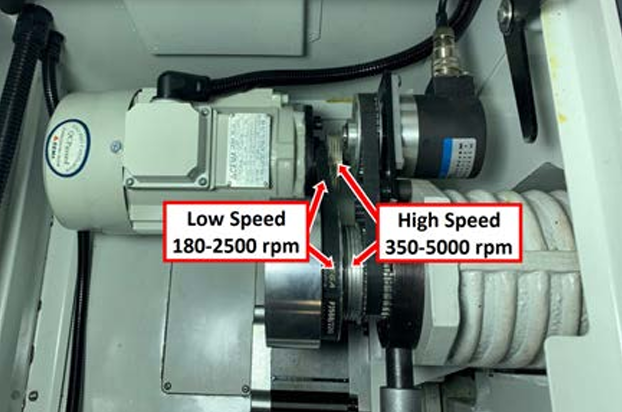
Change the Spindle Speed Range
This machine has two spindle speed ranges:
-
High 250 rpm to 7500 rpm
-
Low 70 rpm to 2000 rpm
WARNING! Entanglement / Entrapment Hazard. The machine operates under automatic control — it can start at any time and crush, cut, entangle, or pinch body parts. Always keep clear of positions on the machine where unexpected or unintended machine motion could cause harm. Before operating this machine in any way, you must verify that all operators know the location of the machine's Emergency Stop button.
To change the spindle speed range:
-
Power off the machine and the PathPilot controller.
-
Push in the machine's red Emergency Stop button, which removes power to motion control.
-
From the PathPilot interface, select Exit.
-
Turn the Main Disconnect switch to OFF on the side of the electrical cabinet.
-
Follow correct lockout/tagout procedures.
-
-
Open the spindle cabinet door.
-
Loosen the 8 mm socket head cap screw on the far side of the motor mount with a 6 mm hex wrench.
-
Lift the spindle motor up (it tilts toward you, pivoting about the remaining screw). The spindle belt slackens, which allows you to move the belt from one pulley to the other.
-
With the spindle belt in its new position, retighten the 8 mm socket head cap screw that you loosened in Step 3.
-
Rotate the spindle by hand to visually confirm that the spindle belt is fully seated in the pulley.
-
Close the spindle cabinet door.
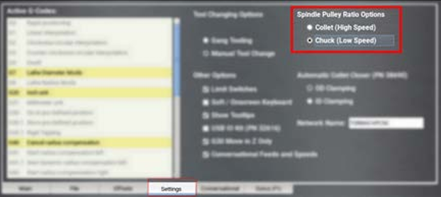
-
From the PathPilot interface, on the Settings tab, select the appropriate spindle pulley ratio option.
Load Material into the Spindle
-
Open the enclosure door and the spindle door. Verify that the latch on both doors is seated to prevent the doors from unexpectedly falling.
-
Install the draw tube through the spindle.
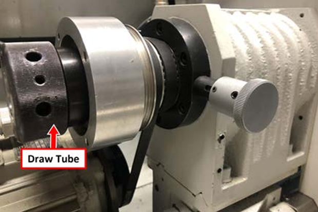
-
Install a 5C collet or chuck into the headstock.
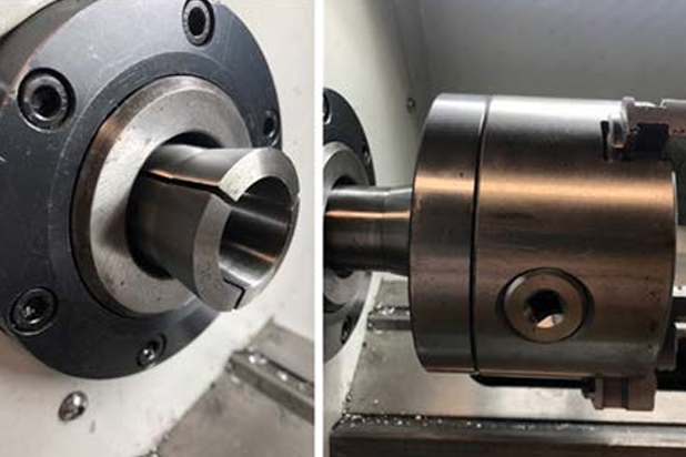
-
Depending on which workholding option you're using, do one of the following:
-
5C Collet Put a piece of stock into the collet, and adjust the length of the stock in the cutting area.
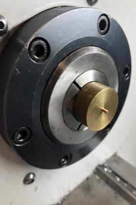
-
Chuck You'll install the stock after the drawtube and the chuck are securely tightened.
-
Gently push on the spindle lock and rotate the spindle with your hand. Stop rotating the spindle once you feel the lock engage.
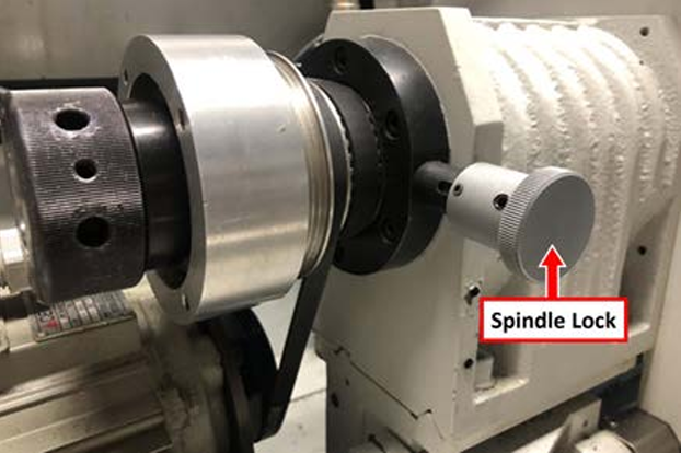
-
Hold the spindle lock with one hand and, using the other hand, tighten the draw tube with the (provided) spanner wrench until the draw tube is tight.
Load G-Code
To run a G-code program on a PathPilot controller, you must first verify that the file is on the controller. For more information on transferring and moving files, see "Transfer Files to and From the Controller" (page 9).
To load G-code:
-
From the File tab, in the Controller Files window, select the desired .nc file.
-
Select Load G-Code.
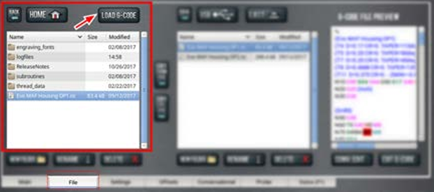
NOTE: This function is only available for files stored on the PathPilot controller.
PathPilot loads the G-code file and opens the Main tab.
Transfer Files to and From the Controller
To run a G-code program, you must transfer the files to the PathPilot controller.
To transfer files to and from the controller:
-
Insert a USB drive into any open USB port.
-
From the File tab, select the file to transfer (either in the USB Files window or the Controller Files window).
NOTE: Select Back to move backward and either Home or USB to move to the highest level.
-
Select the location to which you want to copy the transferred file.
-
Select either Copy From USB or Copy to USB.
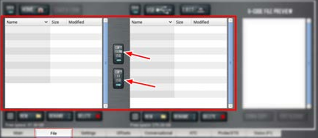
NOTE: The file must have a unique name. If it doesn't, you must either overwrite the file, rename the file, or cancel the file transfer.
-
Select Eject.
It's safe to remove the USB drive from the controller.
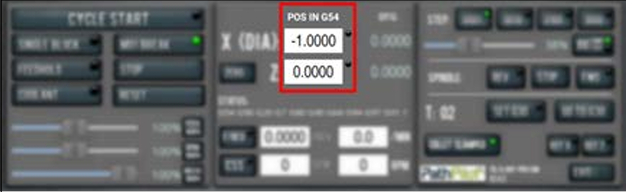
Set Work Offsets
In the the X (Dia) DRO field, all values are expressed in terms of the diameter of the workpiece, not the radius.
Example
If the active tool is 2 in. away from the spindle centerline, 4.000 displays in the X DRO field.
To set the current axis location to zero in the active work coordinate system:
-
Select Zero.
To change work offsets:
-
On the Main tab, in the MDI Line DRO field, type the new work offset to activate (for example, G55). Then select the Enter key.
-
The new work offset displays in the following locations in the PathPilot interface:
-
The Status read-only DRO field.
-
Above the Work Offset DRO fields.
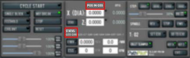
NOTE: The values in the Work Offset DRO fields update to indicate the new location of each axis in the new work offset.
For more information on using work offsets, see "About Work Offsets".
About Work Offsets
Work offsets allow you to think in terms of X and Z coordinates with respect to the part, rather than thinking of them with respect to the machine position. This means that you can jog the machine to an arbitrary location (like the end of a workpiece) and call that location zero.
You can save up to 500 work offsets in PathPilot. The naming structure varies based on the offset number, as detailed in the following table.
|
Work Offset Naming |
||
|
Offsets 1-9 (Use either name) |
||
|
Offset |
Extended Name |
Name |
|
1 |
G54.1 P1 |
G54 |
|
2 |
G54.1 P2 |
G55 |
|
3 |
G54.1 P3 |
G56 |
|
4 |
G54.1 P4 |
G57 |
|
5 |
G54.1 P5 |
G58 |
|
6 |
G54.1 P6 |
G59 |
|
7 |
G54.1 P7 |
G59.1 |
|
8 |
G54.1 P8 |
G59.2 |
|
9 |
G54.1 P9 |
G59.3 |
|
Offsets 10-500 (Use extended name) |
||
|
Offset |
Extended Name |
Name |
|
10 |
G54.1 P10 |
Not used |
|
11 |
G54.1 P11 |
Not used |
|
... |
||
|
499 |
G54.1 P499 |
Not used |
|
500 |
G54.1 P500 |
Not used |
Set Tool Geometry Offsets
Before running a G-code program, PathPilot must know the geometry of the tools that are required for the program. For more information on using tool length offsets, see "About Tool Offsets".
NOTE: You can import a .csv file with tool geometry offset data. For information, see "Import and Export the Tool Table".
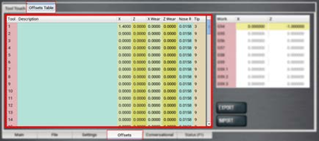
To set tool geometry offsets:
-
Verify that the machine is powered on, out of reset, and the axes have been referenced.
-
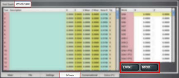
From the PathPilot controller, on the Offsets tab, select the Offsets Table tab.
-
Find the Tool Table window.
-
Touch off the tool geometry offsets. For information, see "Touch Off the Tool Geometry Offsets".
-
(Optional) Select a field to edit. When finished, select the Enter key.
Touch Off the Tool Geometry Offsets
On the Offsets tab, you can use the Tool Touch tab to graphically select a tool, and then touch off the tool to set the geometry offsets.
Tip! When using this method to measure your tool geometry, remember that the X zero location never changes (the spindle centerline is always X = 0), but the Z zero location may change depending on the length of the workpiece that is chucked into the spindle. As long as each tool is measured to a face that has been zeroed, only measure these tools one time or until you replace an insert.
To touch off the tool geometry offsets:
-
From the Offsets tab, on the Tool Touch tab, select a tool.
The tools along the bottom of the screen are front tool post tools (used by machines with a quick-change tool post setup).
NOTE: Gang tooling setups typically use both front and rear tool post tools.
After you select the tool, PathPilot:
-
Sets the tip orientation for the tool, used (along with tip radius) in cutter compensation.
-
Sets the tool type (front tool post or rear tool post), used by the conversational routines to double check the user entry fields in an attempt to try to detect and prevent crashes.
-
Displays the tool touch off dialog.
Touch X
-
Take a skim cut off of the diameter of the workpiece — just long enough to measure the cut surface with a micrometer.
-
Jog the tool away from workpiece in Z, but don't jog the machine in X.
-
Measure the diameter of the skim-cut workpiece with a micrometer.
-
In the Touch X DRO field, type the value that you measured in Step 3.
NOTE: If you're touching off a front tool post tool, verify that the value you enter is positive.
-
Select Touch X.
The LED comes on.
Touch Z
-
Jog the machine toward the part zero (usually the face of the workpiece) in the Z direction.
-
Move the tool so that its cutting edge is just touching the surface of the material and define this as Z = 0. Use a sheet of paper to indicate when the tool is touching the material.
-
Slowly jog the Z-axis until it's approximately 1/4 in. away from part zero on the workpiece.
-
With the paper between the tool and the workpiece, slowly jog the machine until you feel a light pull on the paper.
-
In the Touch Z DRO field, type the thickness of the piece of paper. Then select Touch Z.
About Tool Offsets
Tool offsets allow you to use various tools while still programming with respect to the workpiece. Tools can have different lengths (and, while using gang tooling, different X/Z positions on the carriage).
Tool offsets are broken down into two components:
-
Geometry Offsets Represents the distance from the work offset zero location to the tool’s control point.
NOTE: Unlike on a mill (where G43 must be called out to apply an offset), tool geometry offsets are automatically applied with the Txx tool change command.
-
Wear Offsets
The sign convention for the machine are as follows:
-
Z negative is toward the spindle.
-
X positive is toward the operator.
Sign convention is important when you choose the manual tool change option or the gang tooling option.
All tools mounted for use on the operator side of the workpiece are touched off using positive X (diameter) values, and most X words in part programming for these tools have positive values.
Import and Export the Tool Table
You can manage the tool table using an external .csv file.
Import a .csv File
-
Transfer the .csv file to a USB drive.
-
Insert the USB drive into the PathPilot controller.
-
Confirm that the PathPilot controller is on.
-
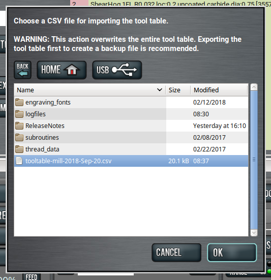
From the Offsets tab, on the Offsets Table tab, select Import.
The Import dialog box displays.
-
Navigate to the .csv file on the USB drive. Then, select OK.
The .csv file updates the tool table.
Export the Tool Table as a .csv File
-
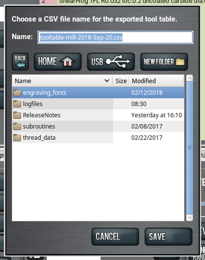
From the Offsets tab, on the Offsets Table tab, select Export.
PathPilot generates the .csv file, and the Export dialog box displays.
-
In the Name DRO field, type the name for the .csv file.
-
Select Save.
The .csv file is saved in the File tab. -
From the File tab, select the newly created .csv file, and then select Copy to USB.
-
Select Eject.
It's safe to remove the USB drive from the controller.
Operate the Coolant Pump
To turn coolant on or off:
-
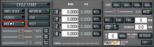
Select Coolant.
For more information on turning on and off coolant, see "About Coolant".
About Coolant
In the PathPilot interface, the Coolant button controls the machine's coolant pump power outlet. The Coolant button’s light shows the current state of the outlet: the light is on when the outlet has power; the light is off when the outlet does not have power.
NOTE: The Coolant button is equivalent to using an M08 (coolant on) or M09 (coolant off) command in the G-code program.
Use the Coolant button before or after a program is running, while a program is running, or while you are using manual data input (MDI) commands.
Looking for more information?
This is a section of the 8L operator's manual. To view the whole manual, go to Tormach document UM10753.
If you have additional questions, we can help. Create a support ticket with Tormach Technical Support at tormach.com/how-to-submit-a-support-ticket for guidance on how to proceed.