10 Pocket Legacy ATC Installation Manual - PCNC 1100
Manual Overview
This manual is intended for use with the Tormach tooling system (TTS) Automatic Tool Changer (ATC) - an accessory to the Tormach PCNC 1100 mill (with PathPilot controller). Readers are assumed to be familiar with the operation and documentation for their particular milling machine. For questions of a general nature (e.g. applying tool height offset compensation) please refer to the PCNC 1100 machine manual.
The Tormach Tooling System System ATC can be used with all existing part programs without modification, regardless of existing tool number assignments. For programs that use 10 tools or fewer the ATC may be used for all tool changes. For part programs requiring more than 10 tools, or for programs requiring special tooling not appropriate for an ATC, such as a reversing tapping head, it can be used in conjunction with manual changes. Any tool number between 1 and 253 may be assigned to a position in the tool tray - you are not confined to using tool numbers 1-10. This is convenient if you have a tool library already set up with tool numbers and heights measured in your tool offset table. The tool changer remembers tools assigned to the tray, and prompts for manual spindle insertion and removal of non-assigned tools at appropriate times. Tools may be assigned to different tray numbers so that, for instance, one can dedicate groups of tray assignments to specific jobs that are run frequently. All tools are called from G-code with standard M6 commands, or from buttons on the ATC control screen.
Safety
Any machine tool is potentially dangerous, especially automated tools under computer control. Because Tormach does not know the details of your workshop or other local conditions, no responsibility can be taken for damage or injury caused by the use of the mill and ATC. It is the owner’s and operators responsibility to understand the mill/ATC system integration and operation and to comply with any legislation and codes of practice applicable to to country or state. If there is any doubt, seek guidance from a professionally qualified expert rather than risk injury.
The safety of any application using the ATC is ultimately the responsibility of those performing the setup and operation. Please do not take this responsibility lightly - use common sense and review all instructions on the operation and maintenance of the ATC.
Operator Safety
When using electric tools, machines or equipment, basic safety precautions should always be followed to reduce the risk of fire, electric shock, and personal injury.
Read and understand this manual. Do not operate the ATC without knowing the function of every control key, button, and alignment and referencing procedure. Refer to this manual or contact Tormach if any function is not understood.
Keep hands clear of the ATC at all times during tool changes or when commanding any ATC motion from the ATC control screen of the mill’s control software.
Avoid contact with moving parts. Before operating the mill and ATC, remove all jewelry including watches and rings, neckties and any loose-fitting clothing. Tie back hair.
Keep hair away from moving parts.
Do not reach for the part, tool or fixture while running a part program.
Keep work area clean. Cluttered areas invite injuries.
Wear ANSI approved eye protection at all times.
Never use longer or larger tools than necessary.
Do not use the ATC or power tools in damp, wet or poorly lit locations.
Do not use tools in the presence of flammable gases or liquids.
Use only identical replacement parts when servicing.
Take off gloves before you operate the ATC. Gloves are easily caught in moving parts or cutting tools.
Never operate with unbalanced tooling.
Never operate the ATC after consuming alcoholic beverages or taking strong medication.
Protect your hands. Stop the machine and ensure that the controller is stopped before you:
Change tools
Change parts or adjust the workpiece
Make an adjustment
Keep work area well lit. Ask for additional light if needed.
Always use proper feeds and speeds, as well as depth and width of cut, to prevent tool breakage.
Use proper cutting tools for the job.
Do not use dull or damaged cutting tools. They break easily and become dangerous projectiles.
Be certain every operator understands the operation and safety requirements of the mill and ATC before operating. It is the responsibility of the owner of the ATC to provide and ensure point of operation safeguarding per OSHA standards.
Electrical Safety
 The Tormach Tooling System (TTS) Automatic Tool Changer (ATC) operates on 70 VDC, fused at 8 amps. It is powered from the DC Bus Board (PN 32005) inside the control cabinet of the mill. Never operate the machine tool with the cabinet door open. Never make or check these connections with the mill powered on.
Power to the ATC and other devices inside the control cabinet may retain dangerous voltages after external power has been removed. Do not modify these connections in any way. If unsure about the connections, call Tormach or a qualified repair technician.
System Requirements
To use the Tormach Tooling System ATC, your machine must meet the following requirements:
You must provide a compressed air source capable of delivering clean, dry air at 95 PSI and 2 CFM.
The Tormach Power Drawbar (PN 31706) must be installed.
For PCNC 1100 machines serial numbers 1325 and lower, you must have previously installed the Spindle Drive Upgrade kit (PN 31090).
For PCNC 1100 machines serial numbers 999 and lower, you must have previously installed the Series 3 upgrade kit (PN 32010).
Required Tools
Metric Allen wrench set
Screwdrivers
Box wrenches and large crescent wrench
Hot glue gun
12” long wooden dowel or round stock
Unpacking and Checking Shipment
Upon receipt, carefully unpack the ATC and inspect to ensure damage did not occur in transit and also to account for all parts. If any damage is apparent, or parts missing, please contact Tormach immediately.
With an assistant, lift the ATC onto a sturdy surface or workbench to prepare it for use.
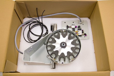
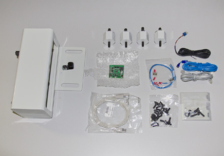
QTY | Description | PN |
1 | ATC assembly | — |
4 | ¼” air lines, one w/ check valve and push fitting | 32226 |
1 | ATC square tube mount | — |
4 | Hex standoffs with M8 and M10 studs | — |
4 | Flange nuts and washers | — |
20 | Nylon M6x16 hex bolts | 32269 |
1 | USB cable | — |
1 | ATC communication RJ-11 cable (512-515) | 32783 |
1 | Main power cable (503,504) terminated with 4 pin Molex and spades | 35433 |
1 | PDB power cable (501,502) terminated with PDB connector and spades | 35434 |
1 | VFD interconnect wiring kit (532-535) | 33213 |
1 | Coolant hose mounting plate w/ fasteners | — |
1 | Power drawbar power supply board | 31980 |
1 | Operator Manual | — |
The following items may or may not be included, depending on machine age and power drawbar installation:
Drawbar with eight spring washers
Power drawbar control circuit board (if required based on age of your power drawbar installation).
DC Bus Board (PN 32005)
Check these items. Notify Tormach of any damage incurred during transit or missing parts so any claims can be made within the shipping carrier’s deadline.
Before You Begin
The Tormach Tooling System ATC is designed for machines with the power drawbar (PN 31706) installed. PCNC 1100 milling machines with serial numbers 1325 and lower will need to have the spindle drive upgrade (PN 31090) installed before installing the ATC. PCNC 1100 machines with serial numbers 999 and lower will also have to have the Series 3 upgrade kit (PN 32010) installed before installing the ATC.
All machines will need to have the power drawbar installed before installing the ATC. See the power drawbar manual (included with the power drawbar package) for installation instructions. PCNC 1100 machines serial numbers 1999 and lower will need to replace the old DC Bus Board (PN 30661) with the new bus board (PN 32005).
Mount ATC
Mounting and aligning the ATC to the mill is a job that is best done with two people. The ATC carousel assembly, which weighs approximately 50 pounds, is cumbersome to lift and position accurately especially when working over the mill’s chip tray. Installation goes smoothly when one person holds the ATC in position while an assistant tightens the fasteners that connect it to the square tube mount.
Initial Hardware Installation
 WARNING! Electrical Shock Hazard: Be sure to power off machine before making any electrical modifications. Failure to do so may result in serious injury or death.
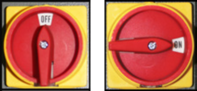
Power Off/On Procedure
Power Off | 1. Push red E-stop button in |
2. Click Exit on screen; when prompted click OK to power off | |
3.Turn Main Disconnect Off |
Power On | 1.Turn Main Disconnect On |
2. After software loads, turn red E-stop clockwise to release | |
3. Press green Start button | |
4. Click Reset on screen |
Installation is easiest if mill is away from the wall.
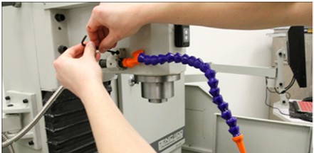
If fitted, relocate coolant hose to spindle head.
If fitted, remove the left hand machine arm from mill.
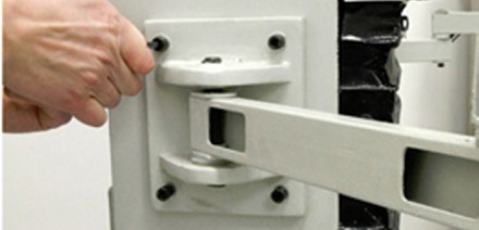
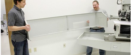
If fitted, remove the upper coolant splash guards (backsplash) from the left and right hand chip trays.
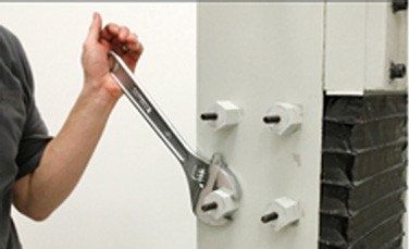
Thread the M8 side of hex standoffs into mill column and tighten securely with a wrench.
Hang the tool changer square tube mount on the M10 studs. Secure with flange nuts and washers. The slots are wider than the stud to allow for minor deviations in hole locations, and to facilitate a small degree of tilt.
With the assistance of another person, fasten the ATC to the mount using the 4 M10 socket head cap screws and flange nuts.
Due to stack up of part tolerances, flexibility, and backlash in the linear bearings, the changer might settle slightly, or sag from horizontal on its mounting system. This is normal. Compensate for minor sag by tilting the mount slightly so the tool tray appears level using a bubble level.
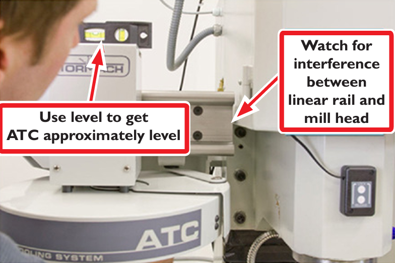
NOTE: Be sure to adjust the mount so that the mill spindle cover sheet metal clears the ATC linear rail. The mount will be fine tuned later in the procedure. Do not tighten the flange nuts down at this point, as you will likely be sliding the ATC a bit before final tightening. Lightly snug the fasteners for now.
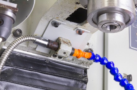
Reroute the coolant hose by mounting the coolant hose clamp to the included coolant plate. Attach the plate to the underside of the spindle head using the two threaded holes on the underside of the spindle head casting.
Electrical Installation
Remove the four column cover plate screws from base of column at the back of the mill. The Z column cover plate will be replaced with the ATC control module. Save the screws.
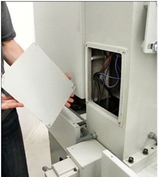
Lay the ATC control module plate with solenoid side down on the chip tray or the Y axis bearing box temporarily.
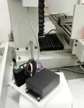
Remove the power drawbar electrical housing (Z axis motor connection box cover plate).
NOTE: If you purchased a power drawbar before June, 2011, you may need to change the power drawbar control circuit board.
Circuit boards labeled Rev 1.2 will need to be replaced. In this case Tormach should have included the updated circuit board with your ATC.
Circuit boards labeled Rev 1.3 and higher do not need to be removed from the housing.
To replace an old (Rev 1.2 or earlier) circuit board, disconnect and remove the old circuit board, taking note of the locations of the connectors. While not necessary, you may find it easier to remove the air lines and the cable carrier as well.
Replace the old drawbar board with the new one. It is easiest to replace the solenoid leads (red and black wire) before re-mounting the circuit board. The solenoid leads go to the opposite side of board from other connectors. This is the only connector on that side (2 pin nylon).
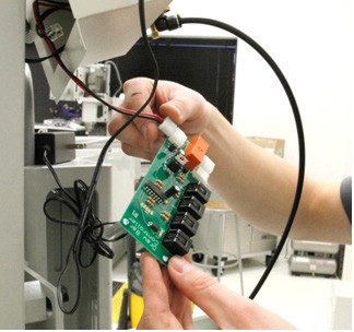
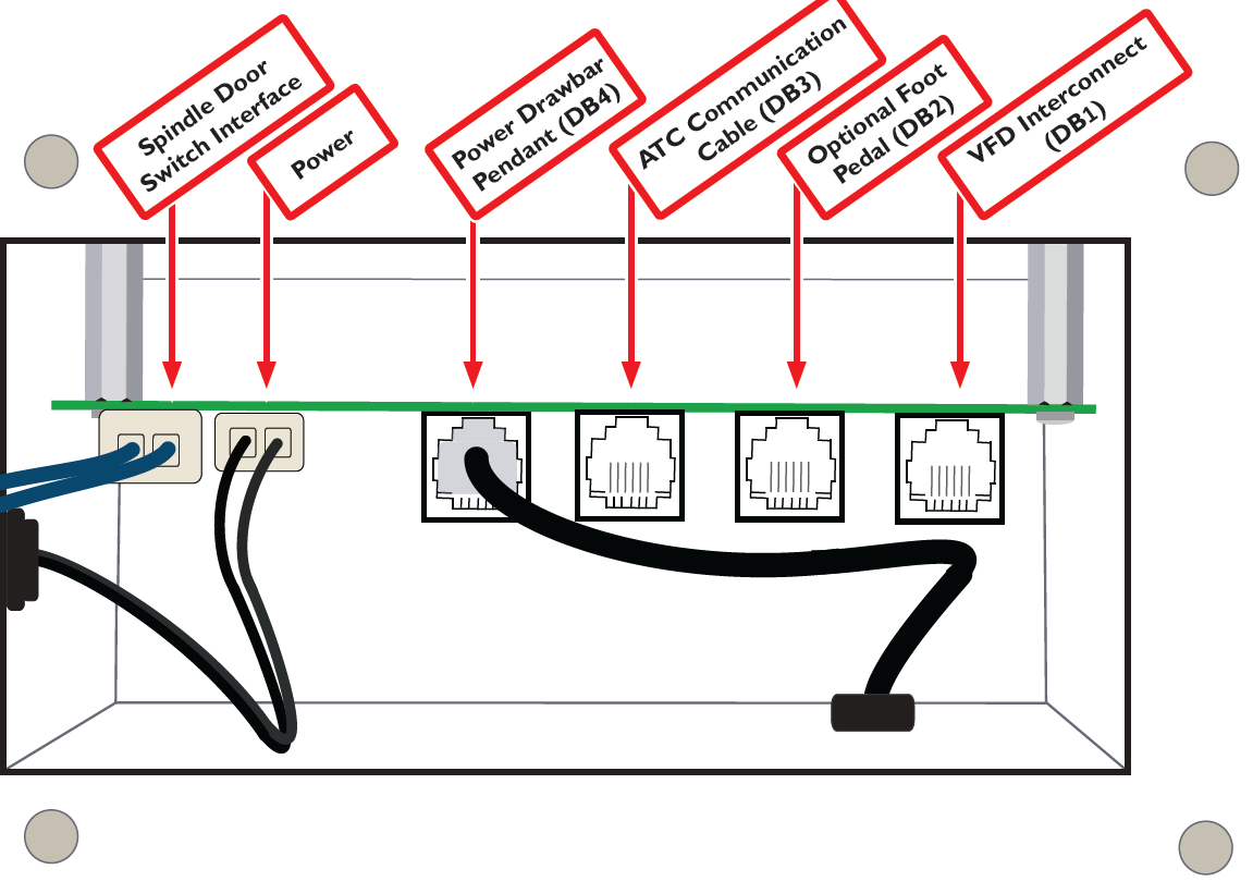
Connect the black VFD interconnect RJ11 cable (with the spade terminal ends) to the DB1 connector on the power drawbar control board, and the ATC communication RJ11 cable to the DB3 connector as shown in the following figure.
Remove the old AC adaptor power supply and replace it with wires 501, 502. These wires will be routed to the new DC Bus Board.
NOTE: If power drawbar and ATC were purchased together, you will not have an AC adaptor power supply.
Route all wires (the two RJ11 cables, the blue spindle door switch interface wires, and the power wires 503, 504) through the mill column.
IMPORTANT: Twist blue spindle door switch interface wires to power drawbar circuit board (105, 105A) and red wires (105A, 106) inside column. These wires carry 110V AC and may cause EMF that disturbs USB signal transmission. Twisting wires cancels this EMF.
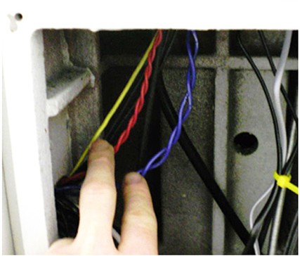
Re-secure the drawbar electrical housing to the Z axis motor connection box cover plate.
Connect the ATC communication RJ11 cable (from the DB3 connector on the power drawbar circuit board) and the USB cable to the ATC control board.
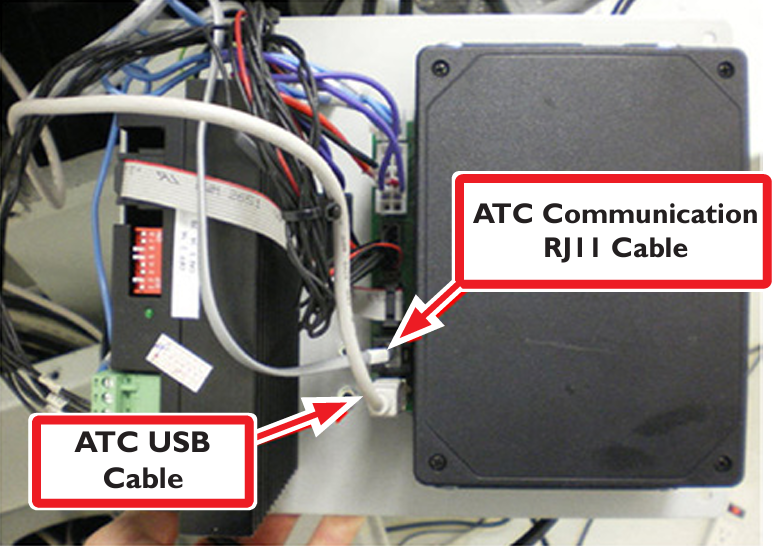
Drop any slack wires from the ATC control module into the Z column, and secure the ATC control module to the back of the mill using the saved M5 screws and into existing column holes. Be sure that extra wire slack does not contact the Y axis ball screw.
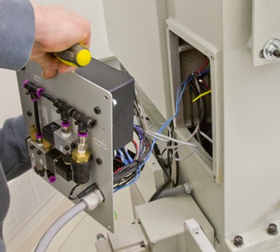
Route the USB cable through the bottom hole of the electric cabinet into any USB port. Do not use the blue USB ports.
 CAUTION! Do not connect the USB cable to the controller until after the software installation is complete.
NOTE: Series 1 machines were not manufactured with this hole. If you have a pre-Series I machine, drill a 5/8” hole in the bottom of your electrical cabinet to route the USB cable to your PathPilot controller.
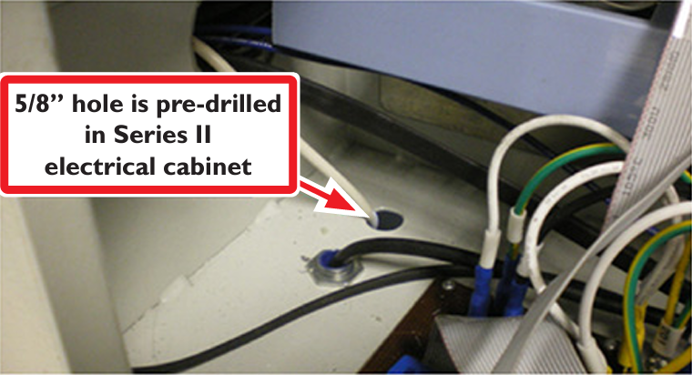
Run the blue ATC control board power leads (503, 504) and the power drawbar circuit board power leads (501, 502) through the wire channels from the hole to the bus board at the top of the cabinet.
Series 3 1100 machines come with the correct DC Bus Board for use with the ATC. Series 3 owners can skip steps 12-13. Do make sure to install the 5x20 mm fuses in the DC Bus Board ATC and PDB fuse holders. This applies to all model machines.
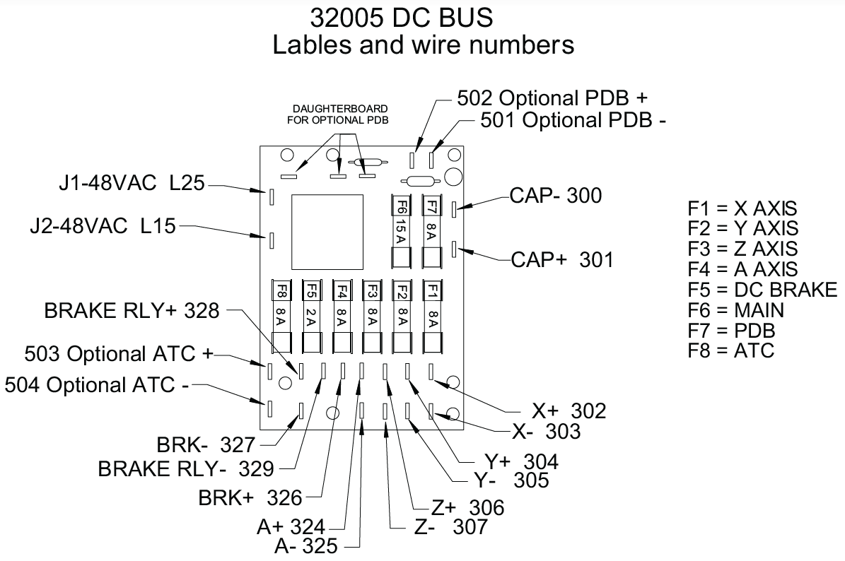
PCNC 1100 machines serial numbers 1999 and lower: Replace the old DC bus board (PN 30661) with the new bus board (PN 32005). Ensure all fuses are present on the DC Bus Board before installation (there should be no empty fuses). When removing the old DC bus board, catch the standoffs and save the screws. Replace with the new board on the same standoffs. It is extremely helpful to tack glue the standoffs in place before mounting the board. An easy way to do this is to put a dab of hot glue on the fasteners before inserting them through the board holes and standoffs.
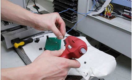
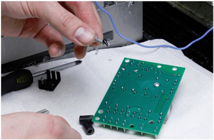
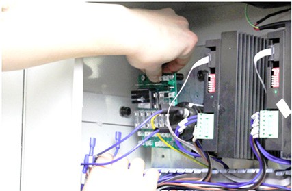
NOTE: Refer to the DC bus board layout diagram on the following page when transferring wires.
Double-check the polarity of the capacitor, stepper driver, and ATC connections before powering up the machine. Reversing polarity will destroy the stepper drivers and ATC control board.
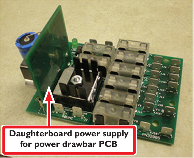
Install the power drawbar daughterboard power supply (PN 31980) by sliding it onto the spade connectors on the new DC bus board (PN 32005). This board supplies the 12V needed by the power drawbar.
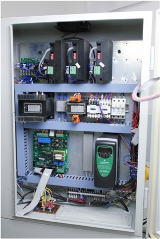
Route the RJ11 VFD interconnect cable along the bottom wire tray to the VFD. Remove the VFD cover by unscrewing the Phillips fastener on the face of the cover plate.
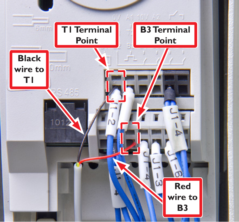
Insert the black and red wires of the RJ-11 cable into positions T1 and B3 on the VFD. To make these connections, insert a small flat head screw driver in the hole just above the wire terminal to open the terminal.
Tidy up the wires and replace the cable tray covers.
Air Line Connection and Requirements
It is recommended to use a filter/dryer/lubricator on the air line used to supply the ATC. Air supply requirements depend on frequency of tool changes. For successful operation, your compressor will need to be able to maintain 95 PSI to the ATC. Typically consumption for frequent tool changes is less than 4 CFM at 95 PSI.
Please note that not all regulators are created equal. Inexpensive regulators tend to constrict air flow, which makes for longer make-up times as the power drawbar fires. While this is not a problem for the power drawbar when operated by hand (the user just waits the extra second or two for the cylinder to fully pressurize), it can cause problems when using the ATC, which only pauses 500 ms between the drawbar firing and the Z axis moving. Better regulators do not restrict the flow while regulating pressure.
Connect Air Lines
Manually pull the tool tray to the retracted position by pulling on the motor enclosure or it will retract suddenly when you pressurize the air lines.
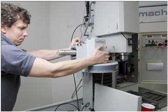
Route the air lines. The lines are labeled at each end – connect them to the solenoids/fittings with the same labels.
Connect the air line from your compressor to the left side input connector labeled “AIR-IN.” You can remove the push fitting and use a quick connect against the first tee if desired, but we’ve found it easier to run tubing to a quick connect fitting in an easier-to-reach location.
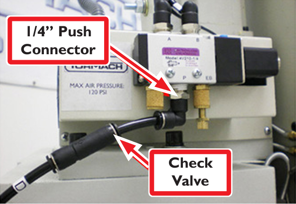
Thread the ¼ NPT push fitting into the air input port of the power drawbar. Connect the power drawbar air line labeled “D” (with the attached check valve) between the “DRAWBAR” push fitting on the right side of the ATC solenoid panel and the drawbar input push fitting on the drawbar solenoid. The check valve allows air to pass in one direction only – if you install it backwards the power drawbar will not operate.
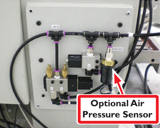
If you have purchased the optional pressure sensor (PN 32329), splice it into air line D and insert the electrical connector into the jack on the column cover plate as shown in this photo:
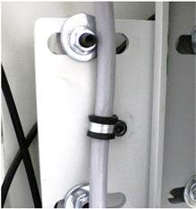
Use the P-clamp to secure the grey ATC control cable to the box beam, allowing enough slack for the carousel’s range of motion:
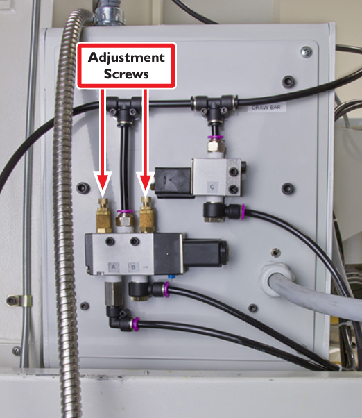
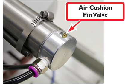
The tray solenoid valve has adjustment screws on the exhaust filters. These can be adjusted to control the tray in and tray out speeds. The screws have been pre-adjusted before shipping. Air cushion pin valves at either end of the air cylinder can be adjusted to control damping at extreme ends of cylinder travel. These are also pre-adjusted. Tool change time should not be adjusted to less than 8 seconds. Conversely, moving too slowly will trigger an ATC time-out error condition.
ATC Communications
Connect the USB cable from the ATC controller to the PathPilot controller and power on the PathPilot controller. When the system comes up, power on the milling machine, bring it out of reset, and reference the axes. Enable the ATC by checking the ATC check button on the Settings Screen. You will see a new tab labeled “ATC” appear along the row of notebook tabs. If the PathPilot cannot establish communication with the ATC within a few seconds of enabling it, you will see an error message instructing you to check the cables or fuse for the ATC. Otherwise, if no error message is seen, the ATC is working properly. Switch to the ATC tab for the following steps.
NOTE: If there is a tool in the spindle, remove it and set the Tool digital read out (DRO) to zero before continuing with these instructions.
Verify the operation of the tool changer:
Apply a thin film of way oil to the linear rails of the ATC slide assembly. Some chatter is expected until the oil has lubricated the linear bearings.
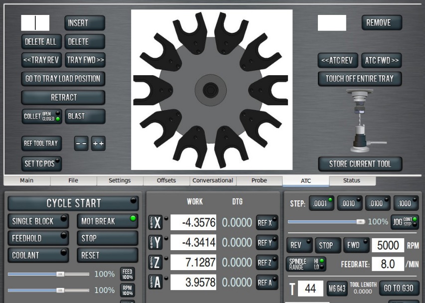
With the tray out jog the Z axis down a couple of inches.
Make sure when doing this that the spindle cover sheet metal will not hit the ATC linear rail. If there is interference, adjust the X position of the ATC by loosening the fasteners that attach the ATC to the square tube mount.
On the ATC screen, click the “Go to Tray Load Position” button. The Z axis will move up to the reference position and the tray will move in.
On the status screen, verify that the tray in sensor is working by looking at the tray in LED – it should be illuminated. If it is not, please refer to the Maintenance and Troubleshooting chapter.
Press the Retract button on the ATC screen. The tray should retract.
Click the “Reference Tool Tray” button on the ATC Setup screen – it should find and center on its home switch. It will turn until it finds one end of the sensor, then reverse and find the other end of the sensor, and then center between these two spots.
Test the drawbar pendant with the spindle off.
On the ATC screen, click the Collet Open/Closed button. The drawbar should operate accordingly.
Click Collet Open/Closed button on the ATC screen. It should fire and latch. Now hit the top (Lock) button on the pendant. It should unlatch.
Click Blast button on the ATC screen. You should hear the air start and stop at the nozzles in the tool tray.
With a tool in the spindle and the tray in the out position, start the spindle at low speed in manual mode; on the status screen verify that the VFD Running LED is illuminated.
Optional pressure sensor verification: If you have installed the pressure sensor accessory (PN 32329) you may verify that the Pressure Sensor LED on the Status is illuminated under low pressure conditions and dark under normal pressure conditions.
Align Tool Tray and Slots
Accurate alignment of the tool tray and slots, and the drawbar throw, are the most important factors in assuring reliable and repeatable tool changer operation. Take your time, and take care to do this accurately. Videos of the alignment procedure can be viewed on our Web site: http://www.tormach.com/upgrades_tts_atc.html
Before you begin the ATC alignment, we recommend replacing your old TTS collet with the new one included with this kit. If this is being installed on a new machine, then consider this collet a spare. Be sure to follow the procedure in the Power Drawbar installation document to properly set the drawbar preload.
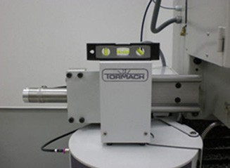
It is helpful to get the ATC assembly approximately level using a bubble level before beginning the alignment procedure.
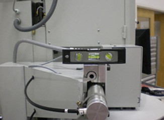
Make sure the spindle is initially empty. There should be no tool holder in the spindle at this point.
Click the “Go To Tray Load Position” button on the ATC screen. The Z axis will jog up and the tray will actuate in, opening the tool access door, and the drawbar will actuate.
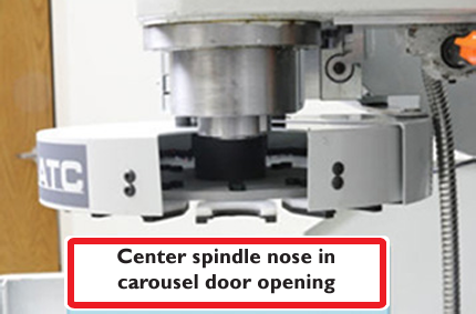
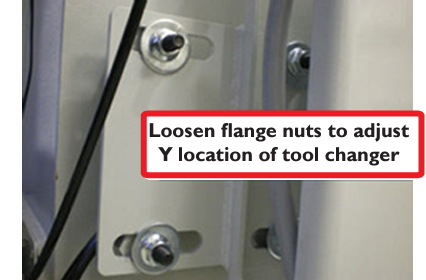
Verify that the spindle is roughly in the center of the carousel door opening. If necessary, move the ATC forward or backward by loosening the four flange nuts that hold the square tube mount to the column.
Insert a long (12-14”) dowel or piece of round stock into a TTS tool holder. Insert the tool holder into the fork of the exposed tray slot. Note: the tool holder should NOT rest on top of the white plastic spring – the groove in the tool holder should slide along the metal portion of the tool fork. Using other vertical lines (edge of mill column, T slots in table) sight along the dowel and check whether the dowel and the spindle axis are parallel in both X and Y planes.
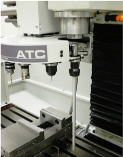
If the dowel and the spindle axis are not parallel, adjust the tilt of the ATC in both X and Y directions until they are.
Tilt in the Y direction is facilitated by loosening the flange nuts that hold the square tube mount to the column, then gently tapping the ATC trapezoid mount with a mallet.
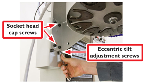
Tilt in the X direction can be adjusted by loosening the socket head cap screws that mount the ATC to the square tube, then turning the eccentric adjustment screws. This is best done with the ATC in the “Tray In” position, as the center of gravity of the unit in the “Tray In” position will allow you to use both adjustment screws to tilt the ATC.
c. Verify that the tool holder shank is parallel to the spindle axis in both X and Y by using an angle block or 1-2-3 block with a straightedge:
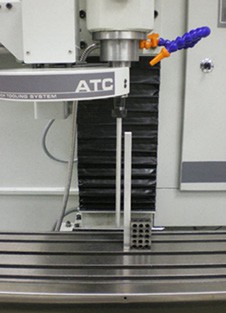
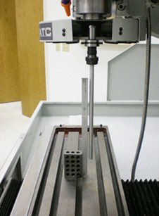
Once you are satisfied that the axis of the dowel is parallel to the spindle axis in both X and Y, jog the spindle down to the top of the Tormach tool holder shank. Do not go all the way down to the shoulder yet. Verify by eye that it is roughly centered on the collet center opening.
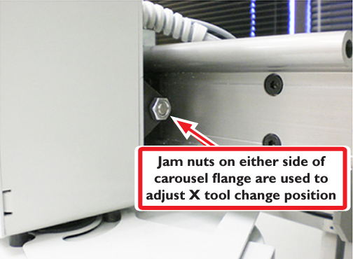
To adjust the alignment of the tool holder to the collet in the X direction, loosen the jam nut at the end of the tray cylinder rod and move it to a roughly centered position. Press “Tray In” to verify the adjustment. You will likely have to repeat this procedure several times to get the location correct.
b. To adjust the alignment of the tool holder to the collet in the Y direction, use the “--“or “++” buttons on the ATC Setup screen Alignment section. It is best to wiggle the fork with your thumb and index finger to feel the extremes of the carousel backlash against the spindle with your fingers to see that it is roughly centered left and right of fork while making this adjustment.
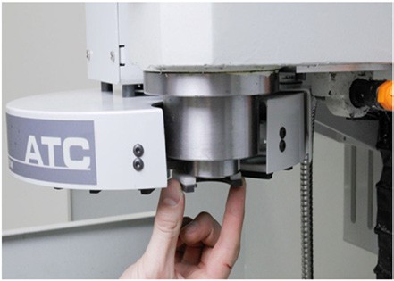
Remove the tool from the tray, then jog the Z axis back down until the spindle is just above the tool fork. Visually check that the tray is level and on a parallel plane to the underside of the spindle. You should see the same distance between the tool fork and the spindle face around the perimeter of the spindle.
Now, pull your hand away, and click “Reference tool tray.” It will return to the newly centered position. Once the first slot is oriented, all other slots will stop in the same relative position. The ATC will remember this offset indefinitely, until it is reset by the same procedure. This is now the reference location for the ATC.
We’re now ready to verify the alignment. First, verify that the power drawbar is adjusted correctly. The drawbar should be adjusted so that a tool holder will fall out of the spindle when the drawbar is actuated. Drawbar adjustment is discussed in the power drawbar installation manual.
Test ATC Alignment
Click “Go To Tray Load Position” on the ATC screen.
Push the TTS tool holder with dowel into the open slot in the tool tray.
Slowly jog Z down until the TTS shoulder touches the spindle nose. It should slide smoothly on the TTS shank. If it doesn’t, the tray is misaligned (not centered or perpendicular to the spindle), or the collet hasn’t opened far enough to spring out for smooth entry.
NOTE: If tray is not properly aligned there will be noticeable movement at the end of the dowel as the spindle slides down over tool shank. This must be corrected by adjusting either the tilt or the XY location of forks to ensure trouble-free operation.
Once you get aligned for a smooth descent, jog Z to the shoulder. When the spindle is resting on the tool shoulder, click the “Set TC POS” button on the ATC screen.
You’ve now set the tool change location of the Z axis for all tool changes. This position is remembered as a machine coordinate, is saved at shutdown, and is
independent of all work or tool offsets established during machining. As long as Z is referenced, the tool change will occur at the same place.
After setting the tool change location, jog the Z axis back up off of the tool shank and remove the tool from the fork.
Now check the individual fork alignment. During shipping or assembly, the forks in the tool tray can shift a bit off center. The tool holding forks need to all line up the same way under the spindle. Jog the spindle up slightly, then on the ATC Control screen click the Tray FWD button to index the carousel to the next tool fork. Jog Z down to so the spindle is touching the top of the fork spring. Push the spring left or right until it is roughly centered using the thumb and index finger technique employed in step 7 in the previous section (Align tool Tray and Slots). If the alignment is off, you might have to jog up and loosen the nylon bolts a tad first. Jog up and tighten the nylon bolts at center until snug but not overly tight. Repeat to align all the slots.
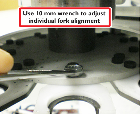
You should only have to do this once. At this point all the forks will align identically to the spindle and work as SLOT 1 did. You may verify this by hitting the “Go To Tray Load Position” button and advancing through each of the tool positions. With the drawbar actuated, insert a tool holder in the slot, jog down towards Tool Change Z. When finished, click “Go To Tray Load Position” to move the spindle away from the tool, then manually remove the tool from the fork. Your system, once aligned and verified, is ready for use.
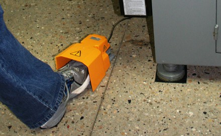
Foot Pedal Kit
The Foot Pedal Kit (PN 31728) provides easy foot-activation of the power drawbar for hands-free operation. To install:
Remove the power drawbar electrical housing.
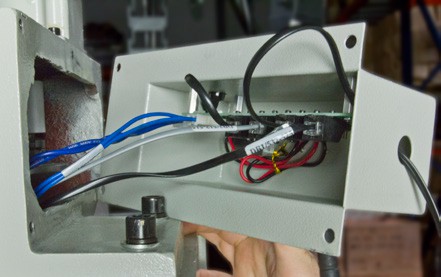
Plug the foot pedal cable into the Foot Pedal connector port on the power drawbar control board (as shown in the figure below).
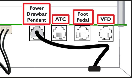
Place the foot pedal in a position that allows for easy access during mill operation.
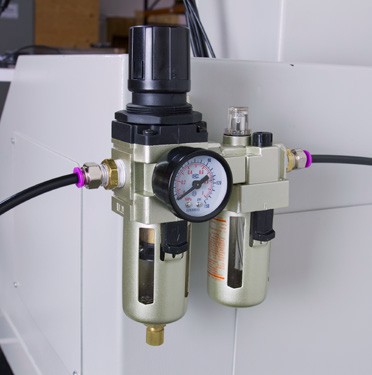
Filter Regulator Lubricator (FRL)
The Filter Regulator Lubricator (PN 32457) is recommended for proper conditioning of supply air for both the power drawbar and the ATC.
To install:
Drill two holes into the back of the splash guard (or wherever is convenient for mills without a splash guard).
Secure the FRL to the mounting bracket with your own equipment.
Wrap the fittings on the two NPT reducers with Teflon tape and secure the fittings into the FRL valve housings.
Splice the air supply line and insert a quick connect bushing (PN 32212) to each end of the open line.
Connect the bushings to the NPT reducers.
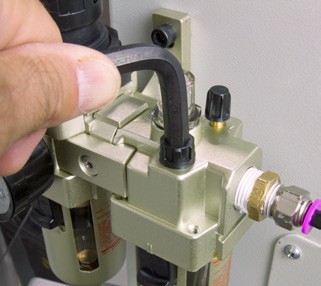
Open the FRL fill port with a hex key.
Fill the port with standard air tool oil (using a small funnel if necessary).
NOTE: Before first use, air must be flushed from the FRL system.
NOTE: Proper function may be confirmed visually through the sight glass on the top of the FRL.
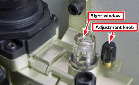
A droplet of lubricant will form on the bottom of the stem located inside of the sight window.
Open the lube adjustment knob 1/2 turn (towards the +).
Flush all air bubbles from the system.
When air bubbles no longer appear in the sight window and a droplet of lubricant forms on the bottom of the stem, close the lube adjustment knob 1/4 turn (so that it is open approximately 1/4 turn from the closed position).
Pressure Sensor
Pressure Sensor (PN 32329) prevents the carousel from actuating during low air supply pressure condition.
Splice air line D and insert the Pressure Sensor as shown.
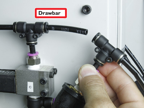
Plug the male end of the electrical connector into the jack on the column cover plate.
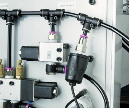
Operation
The Tormach Tooling System ATC will hold up to ten tools in a single tray. The ATC allows mixing manual and automatic tool changes within the same part program. If your program requires 11 or more tools, the ATC will change tools automatically for all tools in its tray, and pause for a manual change for tools that are not assigned to the tray. Any tool number between 1 and 256 may be assigned to a position in the tool tray – you are not confined to using tool numbers 1-10. This is convenient if you have a tool library already set up with tool numbers and heights measured in your tool offset table. There is no need to remember which slot a particular tool has been assigned to – simply call the tool number in G-code with an M6 command and the ATC will retrieve the appropriate tool.
Loading/Unloading Tools
There are two ways to load and unload the tool tray in preparation for machining using the ATC. In automatic tool loading via the Store Current Tool button, the ATC will load the tool that is currently in the spindle and store it in the nearest open tray slot. In manual tool loading, the tray will slide in and the tray door will open, allowing the operator to manually place tools into the tray. The following sections detail these two modes of operation.
Automatic Tray Load/Unload
The right hand side of the ATC control screen contains the buttons and a DRO used to store and retrieve tools. To load a tool into the tray:
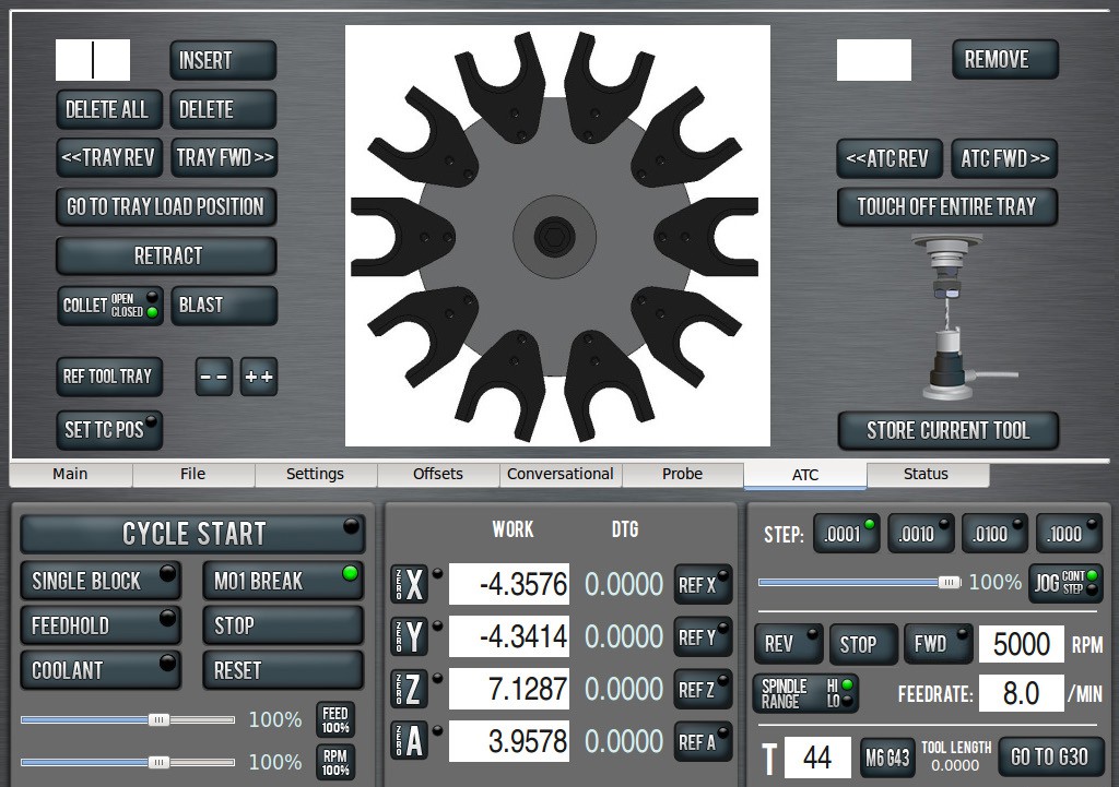
Load the desired tool into the spindle.
Enter the tool number in the tool DRO (bottom right portion of screen next to the M6 G43 button). Do not forget to press “Enter” after typing in this number.
Click the “Store Current Tool” button. The ATC will assign the tool to the nearest open slot and store the tool in that slot in the tray. The tool number will now be displayed on the tray image in the center of the screen. The spindle is now ready for the next tool to be stored.
To retrieve a tool from the tray there are two options. You can type Txx M6 at the MDI line (where xx is the desired tool number) or enter the tool number in the tool DRO and press the Enter key. This will retrieve that tool from the tray and leave it in the spindle. It also leaves it assigned to the tray.
To remove a tool from the tray, type in the tool number in the DRO next to the “Remove” button (remember to press enter after typing in the tool number), then click “Remove.” After the ATC fetches the tool you will be prompted to remove the tool from the spindle.
To remove a tool from the spindle, and delete its assignment from the tray, click “Remove.” You will be prompted to remove the spindle tool.
NOTE: Simply typing a new tool number into the tool DRO does not remove the tray assignment. You must use the “Remove” button to delete the tool’s tray assignment.
“ATC FWD” and “ATC REV” will return the spindle tool to the tray, then fetch the next/previous tool in the tray.
Manual Tray Load/Unload
If you want to load or unload multiple tools you may find it faster to open the tool changer door and load or unload them manually. The Manual Load/Unload buttons and DRO on the right hand side of the ATC screen will allow you to bring the tray to a loading position (door open), manually insert or delete, and assign or un-assign tool numbers to tray positions.
To load tools manually:
Click “Go To Tray Load Position” to move the spindle head up and bring the ATC in to the door open position.
Insert a tool into an open fork.
Type the tool number into the DRO next to the “Insert” button. Remember to press “Enter” after typing in the number.
Click “Insert” to assign the tool to the exposed tray slot.
Click “Tray FWD” or “Tray REV” to advance to the next location if you want to load another tool.
To unload tools manually:
Click “Go To Tray Load Position” to move the spindle head up and bring the ATC in to the door open position.
If the exposed tool is the one you want to remove, simply click “Delete” to un-assign the tool from the tray.
If the tool you want to remove is not the exposed tool, type the tool number into the DRO next to the “Insert” button. Remember to press enter after typing in the number.
Click “Delete” to un-assign the tool. The tray will move to the tool to be removed.
Click “Tray FWD” or “Tray REV” to advance to the next location if you want to unload the next or previous tool.
When you are finished loading or unloading tools, call any tool (using the tool DRO or with an M6 command at the MDI line) or click “Retract” to return the tray to machining position.
NOTE: If you click “Delete” or “Insert” and the ATC is not in tray load position, it will move to tray load position automatically.
Tool Touch-off Routine
If you have the optional TTS Tool Setter (PN 31875) the ATC control software can be used to automatically measure the tool height offset for every tool in the tray. To use this feature, plug the Tool Setter into the accessory port and test communication by actuating the Tool Setter by hand and ensuring that the green Tool Setter LED on the ATC Control screen lights up. Center the Tool Setter directly under the spindle and click the “Touch Off Entire Tray” button on the ATC Control screen. The ATC will cycle through every tool in the tray and enter the measured tool length in the tool table. A few things to note about tool touch-off:
Tools with large diameters (greater than the diameter of the Tool Setter pad) will not be accurately measured unless the cutting edge of the tool makes contact with the Tool Setter. For instance, care must be taken when using the “Touch Off Entire Tray” routine with a fly cutter or shell mill in the tray.
Unless you set up the sensor height of your Tool Setter before touching off the tools, the tool lengths entered in your tool table will be relative, not true tool lengths. You must set up the Tool Setter sensor height to mix ATC tools that have been measured using the Tool Setter with tools that have been measured on a granite black and height gauge. Setting the sensor height is described in detail in the PCNC 1100 operator manual.
ATC Bypass
To bypass the ATC, click the Manual Tool Change check button on the Settings screen.
When the Manual Tool Change option is selected, the ATC is prevented from executing any tool changes. Instead you will be prompted by the software to manually complete any tool changes that are called within a program.
Maintenance
The Tormach Tooling System Automatic Tool Changer requires little maintenance. Periodically inspect the following:
Ensure that your air is clean and dry. A filter/ regulator unit should be sufficient for supplying dry air, as long as you periodically drain your compressor.
The linear guides should be periodically wiped clean and given a light coat of way oil.
The Delrin bearing on the carousel door should be periodically oiled with way oil.
If chips accumulate inside the carousel, it is advised to blow chips clear of the carousel and tray to prevent them from obstructing tool changes. (Always wear eye protection).
Additionally, after installing the ATC you may find that you are using your power drawbar more frequently. Power drawbar maintenance items to consider are:
Periodically tighten the set screw on the spindle flange.
Periodically ensure that mounting hardware is snug and fasteners are tight.
Spring washers are wear items that have a service life of ~30,000 tool changes. If you experience collet slip or notice deterioration of the spring washers, replace them according to the procedure outlined in the power drawbar installation technical document.
For more information, refer to Troubleshooting section in TD10039, PCNC 1100 Power Drawbar Installation.
Troubleshooting
Mechanical Issues
Binding
If your ATC has not been properly aligned you may experience binding as the collet descends over the tool holder shank. The ATC carousel must be in a plane perpendicular to the spindle axis. The best way to check this is to place a long dowel in a drill chuck or set screw tool holder, then position that tool holder in an open tray slot. As you jog the spindle down over the tool holder shank, watch the end of the dowel. If the ATC is properly aligned, the end of the dowel won’t move as the collet slides over the shank. Aligning the ATC is time consuming to do properly, but once set the alignment should not change.
Collet Slip
Collet slip can result from a variety of causes. The best way to prevent collet slip is to make sure that your tool holders and the bore of the TTS R8 collet are clean and dry. Wiping them down with alcohol or acetone is a good way to remove way oil or cutting fluid that may cause collet slip.
The procedure for adjusting the preload on the spring washers is outlined in the power drawbar installation guide. Because the spring washer preload also affects the operation of the ATC, certain parts of this procedure are worth repeating here:
When adjusting the preload, make sure the regulator on your air line set to at or below the cut in pressure on your air compressor. For instance, if your regulator switches on at 90 PSI, and your regulator is set to 95 PSI, the actual air pressure at the drawbar could be anywhere between 90 and 95 PSI, depending on the tank pressure. This is bad: if you set spring washer preload when you have 95 PSI to work with, the drawbar will not properly release when PSI decreases to 90, increasing crash risk.
The higher the working air pressure, the more preload you can get on the spring washers. If compressor can be adjusted to maintain 100 PSI, you can run with higher preload than you would at 90 PSI. Minimum recommended air pressure is 95 PSI, but if collet slips, increase supply pressure to get preload up. Do not exceed 120 PSI, the working limit for the power drawbar cylinder.
Not all air regulators are created equal. We have found that inexpensive regulators tend to constrict air flow, which makes for longer make-up times as the power drawbar fires. While this is not a problem for the power drawbar when operated by hand (the user just waits the extra second or two for the cylinder to fully pressurize), it can cause problems when using the ATC, which only pauses 500 ms between the drawbar firing and the Z axis moving. Better regulators do not restrict the flow while regulating pressure.
Collet slip is more likely to occur if your speeds, feeds, or fixturing result in machining operations with a lot of high frequency chatter (end mill “squeal”). We have seen even light cuts result in collet slip if the end mill is squealing or chattering excessively. Usually, such noise and vibration should be avoided for other reasons (poor surface finish, reduced tool life) and tweaking the spindle RPM or increasing the feed rate will tune the chatter out.
ATC Tray Chatter
If the 3 linear bearings that support the carousel are not properly aligned with the linear guides, you may experience chatter on tool changes. Sometimes this chatter can be eliminated with a light application of way oil to the linear guides. If the chatter persists, loosen the 4 M5 Allen head screws that hold the linear bearings on to the carousel assembly. Allow the bearings to self align, then retighten.
Z Height Not Repeatable
If tool change Z height is set incorrectly the tool will not be properly seated against the spindle nose. This problem manifests itself in poor repeatability of tool length compensation. This is a condition that can be hard to diagnose, because a small gap between the tool holder shoulder and spindle nose can be difficult to see. If you suspect that the tools are not seating properly, backlight the tool holder with a flashlight – any gap will become apparent. During tool changes, the spindle should come down and make contact with the shoulder of the tool. If the spindle travels down too far or not enough, there will be a visible gap between the tool holder and the spindle nose. Adjustment of tool change Z height is discussed in section 2.2.6 of this manual.
It is also possible the R8 collet is protruding too far from the spindle nose, this can be the case if the drawbar isn’t tightened down sufficiently or if the gap between the air cylinder bolt head and the top of the drawbar bolt is not large enough. Adjusting the spring washer tension is covered in the Initial Setup section near the end of the PDB installation document. If the gap between the air cylinder bolt and the drawbar is too little, this will over-travel the R8 collet allowing it to hit in the bottom of the pocket of the TTS holders. Remove washers as required to allow full release of the TTS yet still not push the collet as to be contacting the TTS holder. For more information, refer to TD10039, PCNC 1100 Power Drawbar Installation.
Sensors
The ATC uses the following sensors:
TRAY IN
TRAY OUT
TRAY REFERENCE
Pressure switch (optional)
The TRAY IN/OUT sensors are normally open reed switches. TRAY OUT is visible under the band clamp at the end the pneumatic actuator. TRAY IN is hidden in a recess in the linear rail behind the pneumatic cylinder and is not visible unless the cylinder has been removed. The piston of this pneumatic actuator is magnetic – the reed switches are actuated when the piston inside the cylinder comes within 0.100” of the sensor.
When PathPilot is started the ATC goes through initialization, the TRAY IN and TRAY OUT sensors are evaluated. If the ATC software encounters a condition where both sensors return HI or both return LO, an error message is generated. Other checks in the software user the tray sensors to try to prevent crashes – for instance if the TRAY IN sensor is active the ATC will stop you from jogging past the tool change position (a soft limit is triggered).
Diagnostic LEDs are visible on the Status screen. These can be used to verify the sensors. If a sensor is not working as expected, the following possible causes should be investigated:
Defective Sensor
Any magnet can be used to verify whether or not the sensor is working. If you bring a strong magnet near the TRAY IN or TRAY OUT sensors they should return TRUE. If the sensor is working, you can skip to the “Sensor is out of adjustment” section.
If the sensor is not working, you will need to determine whether the sensor itself is defective or if there is a short in the wiring.
NOTE: The TRAY OUT sensor is held in place by a band clamp – if this clamp is over tightened it will prevent the sensor from working. You might try loosening the band clamp as a first step in diagnosing a bad TRAY OUT sensor.
To distinguish between a wiring problem and a sensor problem, you will need to Ohm out the sensor with a multimeter:
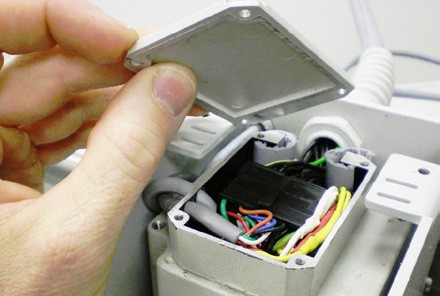
Remove the motor cover, then remove the top of the stepper motor’s electrical junction box:
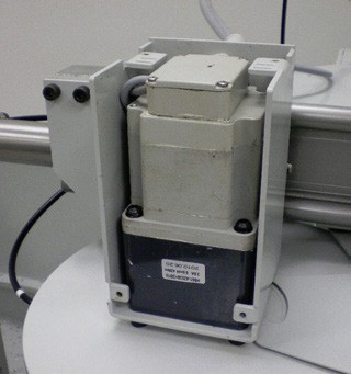
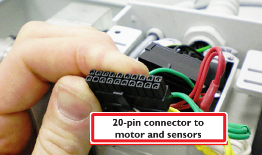
Disconnect the 20 pin Molex connector. The female side goes to the motor and sensors:
Touch your probe leads to the pins corresponding to the sensor of interest:
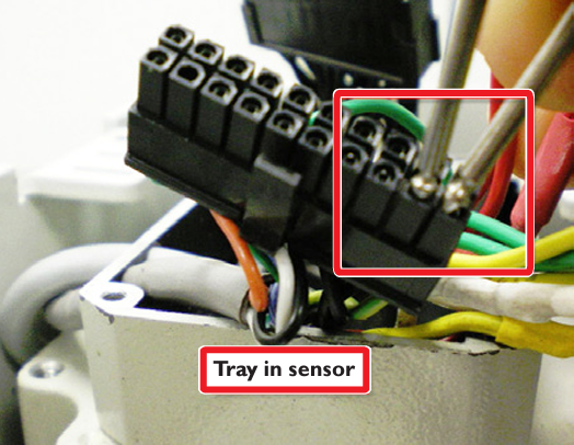
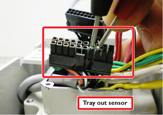
When a magnet is near the sensor, the sensor should read close to 0 Ohms, otherwise it should read open circuit.
If the sensor reads appropriately at the 20 pin connector, then the overwhelming likelihood is that the 20 pin junction (male side – to the control board) has a faulty crimp. To be sure you can repeat the above multimeter tests at the control board (see schematic for appropriate pins).
If the sensor does not read appropriately you should remove the sensor assembly (which requires removal of the pneumatic actuator). As a final check you can ohm out the sensors when they are off of the machine. The sensor assembly is PN 32138.
Sensor Out of Adjustment
If the tray sensors work when you wave a magnet over them, but don’t read the tray position accurately, they are out of adjustment. The magnetic piston must come within about 0.100” of the sensor to activate the sensor. Sprinkling iron filings on the outside of the cylinder is a good way to verify the position of the magnetic piston. You should verify that the sensor is positioned such that the magnetic piston is directly over the sensor when in the tray out or tray in positions. Also, check that the air cushion adjustment (small brass set screw) hasn’t been over-adjusted to a hard stop, which will prevent the piston from traveling all the way to either position.
Tray Reference
The TRAY REFERENCE sensor is a normally open reed switch housed in a black plastic enclosure on the underside of the carousel umbrella. It is used to provide a carousel home reference position. It reads a small neodymium magnet embedded in the hub.
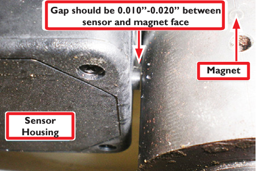
The first tool change after the control software is started, or any time after the mill is e-stopped and then re-powered, the tray will reference itself. It spins quickly in one direction until is the sensor reads the magnet, moves past the magnet, then it reverses direction and moves slowly until it reads the magnet again. If the sensor is not working properly the tray will spin for 10 seconds or so, then time out and give an error message.
The sensor should be positioned as shown in the above photo – a small gap should be present between the magnet embedded in the hub and the sensor itself.
This sensor can be Ohmed out in the same way as the TRAY IN and TRAY OUT sensors:
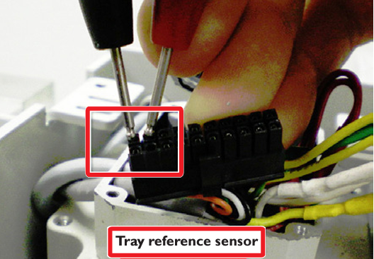

Hub Disassembly
Remove the tool tray by removing the flange nut that attaches the tray to the hub.
Use an Allen wrench to unscrew the stud that the flange nut was screwed on to.
Behind the stud is a small (M4) socket head cap screw; remove this.
Loosen the two set screws and remove the hub from the shaft.
ATC Recovery
As you learn to use the tool changer you may experience a tool crash. Thankfully, it is very difficult to damage the Tormach ATC. The software is intelligent and can predict potential crashes, warning the operator with a pop-up window before executing the commanded change. If you are unfortunate enough to experience a crash:
Use “Drawbar Down” button on the ATC Setup screen or the “Release” and “Lock” buttons on the pendant to release the tool.
Use Reference Z button to move Z axis clear of the ATC.
Use the “Tray Out” button on the ATC Setup screen to retract the tray.
Always re-reference the tool tray after a crash.
Make sure that the tools that are physically in the tray match the tools shown on the ATC control screen.
If there is a mismatch between the software and the actual tools that are present in the tray, click the “Go To Tray Load Position” button and then use the “Insert” and “Delete” buttons to correct the error.
Broken Fork Fasteners
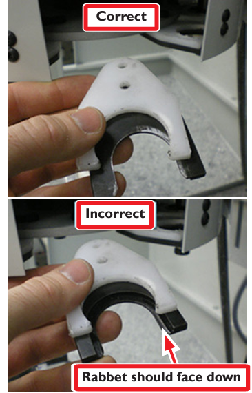
The hex bolts that hold the tool forks to the tray are nylon shear bolts that have been engineered to fail under greater- than-normal loads. These bolts will snap in the event of a tool crash, preventing damage to the ATC. NEVER REPLACE THESE BOLTS WITH METAL FASTENERS! Doing so will put your ATC at risk to more serious damage in the event of a tool crash. If you experience a crash that breaks these shear bolts, replace them with the extra bolts provided with the ATC and realign the tool fork using the procedure described in section 2.3.3. Note that the fork has a U-shaped rabbet on one side. This rabbet must face down as shown in the following photos:
The control software records the positions of the tools in the carousel and spindle in a configuration file when you shut the software down. If you fail to shut the software down before turning off the controller, or if you have a power failure during operation, the software may restart with incorrect tool positions shown on the ATC screen. This is an easy condition to recover from. Perform the following steps to correct this problem:
If there is a tool in the spindle, remove it before proceeding with an ATC recovery.
Click the “Tray Load Position” button on the ATC screen.
Using the “Tray FWD” or “Tray REV” buttons, index through the tray. Use the “Insert” and “Delete” buttons on the Manual Load/Unload section of the ATC control screen until the tools that are physically in the tray match up with the tools shown on the ATC control screen.
To view a PDF version of your manual, go to Tormach document UM10354.
If you have additional questions, we can help. Create a support ticket with Tormach Technical Support at tormach.com/how-to-submit-a-support-ticket for guidance on how to proceed.
