In This Section, You'll Learn:
About the basic operations required for most projects, organized as a suggested project workflow.
Start the Machine
Power on the machine and the PathPilot controller.
-
Turn the Main Disconnect switch to ON on the side of the electrical cabinet.
-
Twist out the machine's red Emergency Stop button, which enables movement to the machine axes and the spindle.
-
Press the Reset button.
Bring the Machine Out of Reset
-
Select Reset.
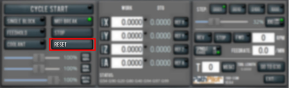
For more information on reset mode, see "About Reset Mode".
About Reset Mode
When the machine is first powered on, or after an emergency stop, the Reset button flashes. When you select the flashing Reset button, PathPilot verifies communication to the machine and does the following activities:
-
Brings the machine out of an emergency stop condition
-
Clears alarms
-
Clears the tool path backplot
-
Resets all modal G-codes to their normal state
-
Rewinds the currently loaded G-code program
-
Stops machine motion, but is not a replacement for the Emergency Stop button
You can select the Reset button any time while the machine is on.
Reference the Machine
-
Verify that the machine can freely move to its reference position (at the ends of travel).
-
To verify that the tooling is clear of any possible obstructions, reference the Z-axis before referencing the other axes: from the PathPilot interface, select Ref Z.
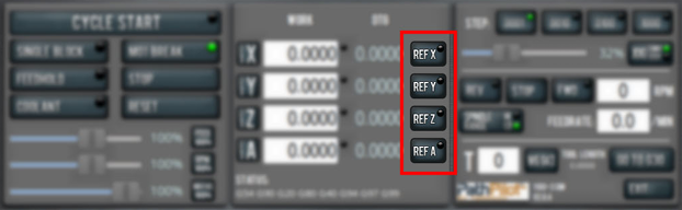
-
Once the spindle is clear of any possible obstructions, continue referencing all axes.
NOTE: You can select the buttons one after another. Once the machine references one axis, it'll move on to the next.
After each axis is referenced, its button light comes on.
For more information on referencing the machine, see "About Referencing".
About Referencing
You must reference the machine to establish a known position for PathPilot. The position that's set while referencing the machine is the origin of the machine coordinate system. Without referencing the machine, PathPilot won't know the current position of the machine axes.
You must reference the machine at the following times:
-
After you power on the machine
-
After you push in the Emergency Stop button
-
Before running a G-code program
-
Before using MDI commands
-
Before setting work or tool offsets
-
After a collision or an axis stall/fault
When referencing, the machine moves each axis to the end of its travel. The machine stops at the limit switch, which sets the axis’ reference position.
Jog the Machine
To switch between jogging modes:
-
From the Manual Control area, in the Jog group, select Jog.
PathPilot toggles between continuous velocity mode and step mode.
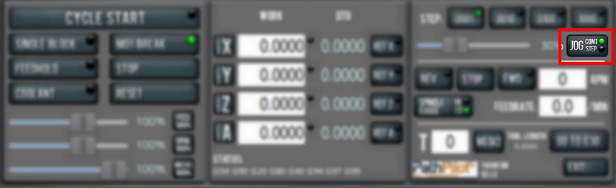
When the Cont green light is on, continuous velocity mode is selected.
When the Step green light is on, step mode is selected.
To use continuous velocity mode:
-
Set the velocity: drag the Jog Speed slider.
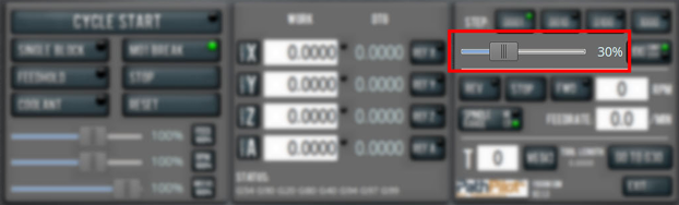
For more information on continuous velocity mode, see "About Continuous Velocity Jogging".
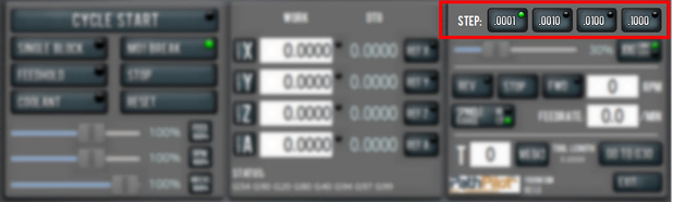
To use step mode, select the step size. Do one of the following, depending on your accessories:
-
In the Manual Control Area, in the Jog group, select the step size.
The Step button's light comes on, indicating which step size is active.
-
On the (optional) Jog Shuttle, press the Step button to toggle the currently selected step size.
In the PathPilot interface, the Step button's light comes on, indicating which step size is active.
For more information on step mode, see "About Step Jogging".
About Jogging
Jogging is the operation of manually moving an axis in various directions (like to set up and indicate fixtures or workpieces). You can't manually jog the machine while it's performing automatic operations (like running a G-code program or an MDI command).
Jog the machine using the keyboard, the optional Jog Shuttle or Operator Console Pendant. Whichever device you're jogging with, you can either:
-
Jog the machine at a consistent velocity (for information, see "About Continuous Velocity Jogging").
-
Jog the machine in steps (for information, see "About Step Jogging").
For more information, see "Jog Controls Reference".
About Continuous Velocity Jogging
While jogging in continuous velocity mode, the machine moves at a constant speed for as long as:
-
A keyboard key is pressed
-
The Jog Shuttle outer ring is twisted away from the neutral position
-
The Operator Console Pendent wheel is turned in the desired direction.
This is useful when you're doing things like:
-
Roughly positioning the machine (for example, to move the spindle head away from the workpiece).
-
Moving the machine a certain distance at a constant speed (for example, to align a vise).
About Step Jogging
While jogging in step mode, the machine moves one step each time you either press a jog key on the keyboard, click the inner wheel of the Jog Shuttle, or rotate the Console Pendant one click. The jog step sizes range depending on the programming mode you are using:
-
Imperial (G20) Mode 0.0001 in. to 0.1000 in.
-
Metric (G21) Mode 0.01 mm to 10 mm
Step jogging mode is useful to finely move the machine, like when you're indicating a workpiece or manually setting tool lengths.
The jog keys on the keyboard only move the machine in steps when step mode is indicated in PathPilot. The inner wheel on the jog shuttle always moves the machine in steps, regardless of which mode is indicated in PathPilot.
Jog Controls Reference
The machine’s jogging functions are controlled by the following:
-
The Jog group of the Manual Control area in the PathPilot interface
-
The keyboard
-
The (optional) Jog Shuttle
-
The (optional) Operator Console Pendant
|
Axis |
Direction |
Keyboard Key |
Jog Shuttle |
|
X-Axis |
Positive |
Right Arrow |
Clockwise |
|
Negative |
Left Arrow |
Counterclockwise |
|
|
Y-Axis |
Positive |
Up Arrow |
Clockwise |
|
Negative |
Down Arrow |
Counterclockwise |
|
|
Z-Axis |
Positive |
Page Up |
Clockwise |
|
Negative |
Page Down |
Counterclockwise |
|
|
A-Axis |
Positive |
Period |
Clockwise |
|
Negative |
Comma |
Counterclockwise |
Jogging in PathPilot
From the PathPilot interface, in the Manual Control area, the Jog group has the following functions:
-
The Jog button, which toggles between continuous velocity mode and step mode.
-
The Jog Speed slider, which controls the machine’s jog rate (whether in continuous velocity mode or in step mode).
The jog rate is measured as a percentage of the machine's maximum jog rate.
Jogging with the Keyboard
Pressing the keys results in the following actions:
-
[KEY] jogs the axis at the current jog rate.
-
[KEY]+Shift jogs the axis at the maximum jog rate.
Jogging with the Optional Jog Shuttle or Operator Console Pendant
Both the Jog Shuttle (PN 30616) and Operator Console Pendant (PN 50440) provide manual jogging controls, but with slightly different physical interfaces:
Axis Movement
-
Jog Shuttle:
-
Inner wheel: Precise, incremental jogging. Each detent (click) moves the selected axis by one jog step increment.
-
Outer ring: Smooth, continuous jogging based on rotation speed.
-
-
Pendant:
-
Single wheel: Provides variable-speed jogging based on rotation, similar to the shuttle’s outer ring.
-
Axis Selection
-
Jog Shuttle: Four buttons let you toggle between the X, Y, Z, and A axes.
-
Pendant: A four-position switch selects the active axis.
Note: In PathPilot, the currently selected axis is shown in the Position Status group. A green light appears next to the Axis DRO to indicate the active axis.
Step Size Selection
-
Jog Shuttle: A dedicated Step button toggles between available jog step sizes.
-
Pendant: A three-position switch selects the jog step size.
Manually Control the Spindle
-
Verify that the machine is powered on and out of reset.
-
From the PathPilot interface, in the Manual Control area, locate the Spindle group.
-
Open the spindle motor door.
-
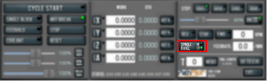
Make sure that the spindle belt position agrees with your desired speed range. If it doesn't, do one of the following:
-
In the PathPilot interface, select Spindle Range.
-
Move the spindle belt.
For information, see "Change the Spindle Speed Range".
-
Close the spindle motor door.
-
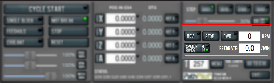
In the RPM DRO field, type the desired RPM speed. Then select the Enter key.
-
Select FWD to start the spindle in the forward direction, or REV to start the spindle in the reverse direction.
-
Select Stop to stop the spindle.
Change the Spindle Speed Range
To change the spindle speed range, you must move the spindle belt inside of the spindle cabinet:
-
Open the spindle motor door.
-
Unclamp the motor mounting plate: Loosen the clamp handle.
This allows the spindle motor plate to pivot. -
Slacken the spindle belt: Pull the pivot handle forward.
-
Move the spindle belt from one set of pulleys to the other.
Two speed ranges are available:
-
Low 70 rpm to 2000 rpm
-
High 250 rpm to 10,000 rpm
-
Tighten the spindle belt: Push the pivot handle backward (toward the machine column).
-
Secure the motor mounting plate: Tighten the clamp
-
Firmly push the spindle belt between the pulleys. If it is properly tensioned, the spindle belt should move between 3 mm and 6 mm. If it's not properly tensioned, repeat Steps 2 through 6.
-
Rotate the clamp hand clockwise.
The spindle motor plate locks in place. -
Close the spindle motor door.
-
From the PathPilot interface, examine the light on the Spindle Range button to make sure that it agrees with the spindle belt's position.
About the Spindle
The machine spindle gives power to the cutting tool, which allows it to remove material from the workpiece. The spindle is driven by the spindle motor.
The machine uses a single-contact BT30 spindle taper. The tool holder contacts only the spindle taper, which keeps it in position. Because of this, there's a gap (2 mm) between the tool holder's flange and the end surface of the spindle nose.
Operate the spindle either manually or by G-code commands (entered in the MDI Line DRO field or programmed into a G-code program). Manually controlling the spindle is useful when you're setting work offsets for tools that require the spindle to be running (like “wiggler”-style edgefinders or coaxial indicators).
The machine's spindle rotates either clockwise (forward) or counterclockwise (reverse) at a specified spindle speed.
Spindle Controls Reference
The spindle speed is measured in revolutions per minute (RPM).
Two speed ranges are available:
-
Low 70 rpm to 2000 rpm
-
High 250 rpm to 10,000 rpm
Use the low speed range when you're using larger cutting tools, or machining materials with lower surface speeds (like steel or stainless steel).
Use the high speed range when you're using smaller cutting tools, or machining materials with higher surface speeds (like aluminum, brass, or plastic).
To move your spindle speed range from one to the other, see "Change the Spindle Speed Range".
Load G-Code
To run a G-code program on a PathPilot controller, you must first verify that the file is on the controller. For more information on transferring and moving files, see "Transfer Files to and From the Controller".
To load G-code:
-
From the File tab, in the Controller Files window, select the desired .nc file.
-
Select Load G-Code.
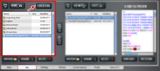
NOTE: This function is only available for files stored on the PathPilot controller.
PathPilot loads the G-code file and opens the Main tab.
Transfer Files to and From the Controller
To run a G-code program, you must transfer the files to the PathPilot controller. You can either use a USB drive or PathPilot HUB (our cloud-based simulator) to transfer files. For more information on PathPilot HUB, go to hub.pathpilot.com.
To transfer files to and from the controller:
-
Either insert a USB drive into any open USB port, or sign in to PathPilot HUB.
-
From the File tab, select the file to transfer (either in the USB / HUB Files window or the Controller Files window).
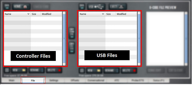
NOTE: Select Back to move backward and either Home or USB to move to the highest level.
-
Select the location to which you want to copy the transferred file.
-
Select either Copy <- or Copy ->.
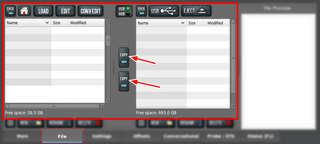
NOTE: The file must have a unique name. If it doesn't, you must either overwrite the file, rename the file, or cancel the file transfer.
-
If you're using a USB drive, select Eject.
It's safe to remove the USB drive from the controller.
Set Up Tooling
Before you begin machining, you must put your cutting tools in tool holders and measure the tool length offsets for each tool.
Install a Tool in a Set Screw Tool Holder
-
Clean the shank of the tool holder with a clean rag. Verify that the shank is free of any grease or oil.
-
Remove the set screw from the tool holder with a hex wrench.
-
Put the desired cutting tool into the tool holder.
-
Replace the set screw in the tool holder, and then completely tighten it with a hex wrench.
Install a Tool in an ER Collet Tool Holder
The ER20 collet is self-extracting: the collet must be mounted in the nut before the nut and collet assembly are put into the collet holder.
If you look closely, you'll notice that the collet nut isn't symmetrical — an area of the retaining ring is cut away. When the collet is correctly mounted in the nut, the collet is pushed forward and out of the collet holder taper while the nut is slightly loosened (which results in self-extraction).
NOTICE! If you don't install the collet in the order specified, there's a risk that the collet and/or nut could be damaged, and the collet's holding capacity could be reduced.
To install a tool in an ER collet tool holder:
-
Hold the collet at an angle, and then insert it into the collet nut as shown in the following image.
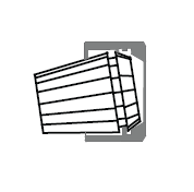
-
Tilt up the collet to snap it into place.
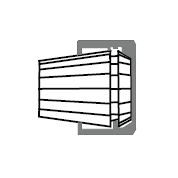
-
Loosely thread the nut on the tool holder, insert the tool, and then tighten the collet.
Install a Drill Chuck in a Jacobs Taper Arbor
-
Assemble the drill chuck on to the Jacobs taper arbor:
-
Use a clean rag and acetone to clean the taper and socket. Verify that the taper and socket are both free of any grease or oil.
-
Retract the jaws: fully open the drill chuck.
-
Use a dead-blow hammer (or similar) to seat the drill chuck on the Jacobs taper arbor.
-
-
Put the drill into the drill chuck.
-
Depending on the type of drill chuck, do one of the following:
-
Keyless Drill Chuck Tighten the drill chuck by hand.
-
Keyed Drill Chuck Use a chuck key to tighten the drill chuck until it is finger tight.
Set Tool Length Offsets
Before running a G-code program, PathPilot must know the length of the tools that are required for the program. For more information on using tool length offsets, see "About Tool Offsets".
NOTE: You can import a .csv file with tool length offset data. For information, see Import and Export the Tool Table.
To set tool length offsets:
-
Verify that the machine is powered on and out of reset.
-
Put a tool into a tool holder, and set it aside to measure.
For information, see "Set Up Tooling". -
From the PathPilot interface, on the Offsets tab, verify that the Tool tab is selected.
-
Find the Tool Table window.
-
Depending on your workflow, you can measure your tools using any of the following methods:
-
Use a Tool Height Setter For information, see "Use a Tool Height Setter to Measure Tools".
-
Use an Electronic Tool Setter For information, see "Use an Electronic Tool Setter (ETS) to Measure Tools".
-
Touch Off of a Known Reference Height For information, see “Touch Off the Tool Length Offsets”.
About Tool Offsets
Tool offsets allow you to use various tools while still programming with respect to the workpiece. Tools can have different lengths (and, while using cutter radius compensation, different diameters).
The most common tool offset is the tool length offset: when you change tools, PathPilot must account for the difference in tool length. In CNC machines, the tool length offset is applied using a G43 command.
The tool length offset is the distance from the cutting edge of the tool to the shoulder of the tool holder.
Before you begin a G-code program, you must verify the lengths of the tools in the program, and make sure that the lengths agree with the tool length offsets set in PathPilot:
-
Each time you change tools, you must apply a new tool length offset in PathPilot.
-
Each time you replace a tool, you must remeasure its length, and apply a new tool length offset in PathPilot.
NOTICE! You must always verify that the physical length of a tool agrees with the tool length offset value set in PathPilot. If you don't, there's a risk that the tool length offset misrepresents the currently active tool in the spindle, which may result in a machine crash or damaged tooling, workpieces, or fixtures.
Touch Off the Tool Length Offsets
Touch off the tool length offsets by using a reference surface with a known height, which gives you a basis to measure any other tool lengths. Use any surface that is parallel (within 0.02 mm) to the machine table. For example:
-
Box parallel
There are two steps to touch off the tool offsets. Complete the following steps in the order listed:
Set a Known Reference Height
This procedure sets a new Z zero position for the currently selected work offset.
To set a known reference height:
-
Identify a precision surface to use as a reference surface (like a 1-2-3 Block Set), and put it below the spindle on the machine table. Verify that there's a clear path from the spindle to the machine table.
-
Set a new, unused work offset (like G55). From the PathPilot interface, on the Main tab, in the MDI Line DRO field, type a work offset. Then select the Enter key.
For information, see "Set Work Offsets". -
If there's already a tool in the spindle, remove it.
-
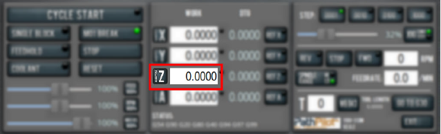
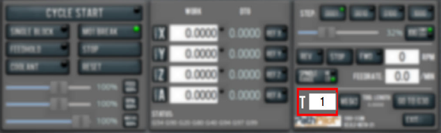
From the PathPilot interface, in the Tool DRO field, type 0. Then select the Enter key.
-
Slowly jog the Z-axis down (-Z) until it's 0.04 in. (1 mm) from the reference surface.
-
Measure the thickness of a piece of paper, and put the paper on the reference surface. Note the thickness of the paper for later.
-
While moving the paper back-and-forth across the reference surface, slowly step the Z-axis down (-Z) until you feel a light pull on the piece of paper. This indicates that the paper is contacting the spindle.
NOTE: It's easier to use step jogging for this task. For information on step jogging, see "About Step Jogging".
-
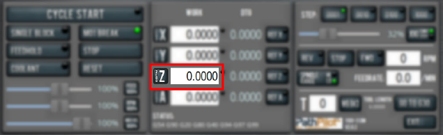
From the PathPilot interface, in the Z-axis work offset DRO field, type the thickness of the piece of paper. Then select the Enter key.
The reference surface is now set as the Z zero position in the current coordinate system.
-
To set the tool length offset, go to “Measure Tools Using a Known Reference Height”.
Measure Tools Using a Known Reference Height
This procedure sets the tool length offset using a known reference height. If you have not yet done so, you must first set the Z zero position; go to “Set a Known Reference Height”.
To measure tools using a known reference height:
-
Verify that the reference surface is still on the machine table with the piece of paper.
-
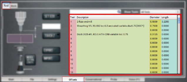
From the PathPilot interface, on the Offsets tab, find an unused tool number in the Tool Table window. Then, type a description for the tool you're measuring.
-
Put the tool holder into the spindle.
-
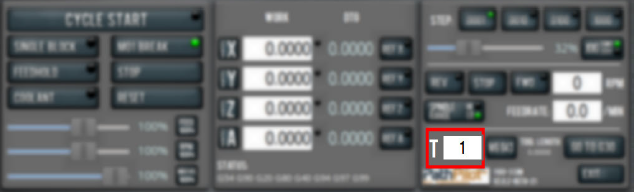
From the PathPilot interface, in the Tool DRO field, type the number of the tool. Then select the Enter key.
-
Slowly jog the Z-axis down (-Z) until it is 0.04 in. (1 mm) from the reference surface.
-
Continue to slowly jog the Z-axis while slowly moving the piece of paper back-and-forth on the reference surface.
-
Stop jogging the Z-axis when you feel a light pull on the piece of paper, which indicates that it is in contact with the tool.
-
From the PathPilot interface, on the Offsets tab, in the Tool Table, select the tool for which you previously wrote a description.
-
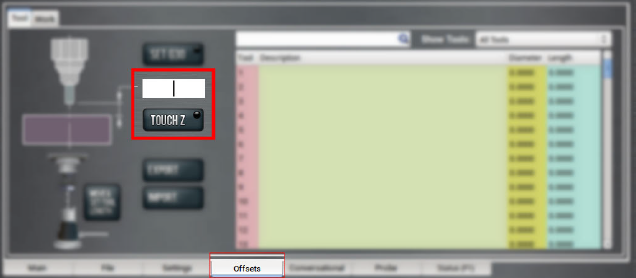
In the Touch Z DRO field, type the thickness of the piece of paper. Then select the Enter key.
-
Select Touch Z.
The length of the tool is stored in the Tool Table window. -
From the Tool Table window, in the Length column, verify that the length of the tool is correct.
-
In the Diameter column, type the diameter of the tool. Then select the Enter key.
-
Jog the Z-axis up (+Z).
You've completed the procedure to measure a tool offset. Repeat this procedure for any remaining tooling you have. Once you're done adding tool length offsets, switch back to your work coordinate system.
Use an Electronic Tool Setter (ETS) to Measure Tools
An ETS is a device used to measure the length of a cutting tool.
To use an ETS to measure tools:
-
Plug in the ETS to the Accessory 2 port.
-
Put the ETS on the known reference surface below the spindle.
-
From the PathPilot interface, on the Offsets tab, in the Tool Table window, in the Description column, type a description for the tool.
-
In the Diameter column, type the diameter of the tool. Then select the Enter key.
-
Put a tool holder into the spindle.
-
From the PathPilot interface, type the tool number in the Tool DRO field. Then select the Enter key.
-
Jog the Z-axis down (-Z) until it is above the ETS.
-
From the Offsets tab, on the Tool tab, select Move and Set Tool Length.
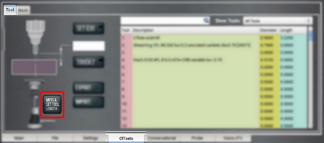
NOTE: Regardless of the initial feed rate, the final touch off feed rate while using an ETS is 2-1/2 in. per minute (IPM).
-
From the Tool Table window, in the Length column, verify that the length of the tool is correct.
Use a Tool Height Setter to Measure Tools
This procedure sets the tool length offset using a known reference height and a Tool Height Setter (PN 39682).
Complete the following steps in the order listed:
Set a Known Reference Height
This procedure sets a new Z zero position for the currently selected work offset.
To set a known reference height:
-
Identify a precision surface to use as a reference surface (like a 1-2-3 Block Set), and put it below the spindle on the machine table. Verify that there's a clear path from the spindle to the machine table.
-
Set a new, unused work offset (like G55). From the PathPilot interface, on the Main tab, in the MDI Line DRO field, type a work offset. Then select the Enter key.
For information, see "Set Work Offsets". -
If there's already a tool in the spindle, remove it.
-
From the PathPilot interface, in the Tool DRO field, type 0. Then select the Enter key.
-
Slowly jog the Z-axis down (-Z) until it's 0.04 in. (1 mm) from the reference surface.
-
Measure the thickness of a piece of paper, and put the paper on the reference surface. Note the thickness of the paper for later.
-
While moving the paper back-and-forth across the reference surface, slowly step the Z-axis down (-Z) until you feel a light pull on the piece of paper. This indicates that the paper is contacting the end face of the spindle.
NOTE: It's easier to use step jogging for this task. For information on step jogging, see "About Step Jogging".
-
From the PathPilot interface, in the Z-axis work offset DRO field, type the thickness of the piece of paper. Then select the Enter key.
The reference surface is now set as the Z zero position in the current coordinate system.
Verify the Calibration of the Tool Height Setter
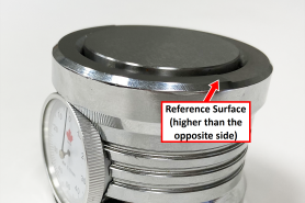
The higher side of the Tool Height Setter is precision ground. You can use it as a reference surface to calibrate the tool.
-
Use the provided dowel pin to compress the setting face of the Tool Height Setter to the level of the ground reference surface.
-
Adjust the indicator dial's bezel to read zero. Make note of how many times the indicator rotates around the dial.
-
Measure the height of the ground reference surface from the bottom surface of the Tool Height Setter with a calipers. Note the measured height for later.
-
Carefully, without moving the bezel, put the Tool Height Setter on the reference surface that's on the machine table.
Set Work Offsets
To set the current axis location to zero in the active work coordinate system:
-
Select Zero [Axis].
To change work offsets:
-
On the Main tab, in the MDI Line DRO field, type the new work offset to activate (for example, G55). Then select the Enter key.
-
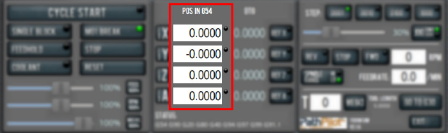
The new work offset displays in the following locations in the PathPilot interface:
-
The Status read-only DRO field.
-
Above the Work Offset DRO fields.
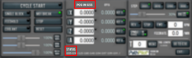
NOTE: The values in the Work Offset DRO fields update to indicate the new location of each axis in the new work offset.
For more information on using work offsets, see "About Work Offsets".
About Work Offsets
Work offsets allow you to think in terms of X, Y, and Z coordinates with respect to the part, rather than thinking of them with respect to the machine position. This means that you can jog the machine to an arbitrary location (like the end of a workpiece) and call that location zero.
You can save up to 500 work offsets in PathPilot. The naming structure varies based on the offset number, as detailed in the following table.
|
Work Offset Naming |
||
|
Offsets 1-9 (Use either name) |
||
|
Offset |
Extended Name |
Name |
|
1 |
G54.1 P1 |
G54 |
|
2 |
G54.1 P2 |
G55 |
|
3 |
G54.1 P3 |
G56 |
|
4 |
G54.1 P4 |
G57 |
|
5 |
G54.1 P5 |
G58 |
|
6 |
G54.1 P6 |
G59 |
|
7 |
G54.1 P7 |
G59.1 |
|
8 |
G54.1 P8 |
G59.2 |
|
9 |
G54.1 P9 |
G59.3 |
|
Offsets 10-500 (Use extended name) |
||
|
Offset |
Extended Name |
Name |
|
10 |
G54.1 P10 |
Not used |
|
11 |
G54.1 P11 |
Not used |
|
... |
||
|
499 |
G54.1 P499 |
Not used |
|
500 |
G54.1 P500 |
Not used |
Operate the Coolant Pump
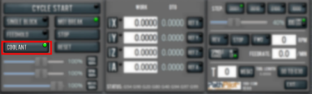
To turn coolant on or off:
-
Select Coolant.
For more information on turning on and off coolant, see "About Coolant".
About Coolant
In the PathPilot interface, the Coolant button controls the machine's coolant pump power outlet. The Coolant button’s light shows the current state of the outlet: the light is on when the outlet has power; the light is off when the outlet does not have power.
NOTE: The Coolant button is equivalent to using an M08 (coolant on) or M09 (coolant off) command in the G-code program.
Use the Coolant button before or after a program is running, while a program is running, or while you are using manual data input (MDI) commands.
Looking for more information?
This is a section of the 1100MX operator's manual. To view the whole manual, go to Tormach document UM10586.
If you have additional questions, we can help. Create a support ticket with Tormach Technical Support at tormach.com/how-to-submit-a-support-ticket for guidance on how to proceed.