Purpose
This document gives instructions on installing an Automatic Collet Closer Kit on a 15L Slant-PRO.
NOTE: The Automatic Collet Closer Kit requires PathPilot v2.2.2 or later. If you haven't yet done so, download and install the latest version of PathPilot.
Product Information
Product: Automatic Collet Closer Kit for 15L Slant-PRO (PN 38690)
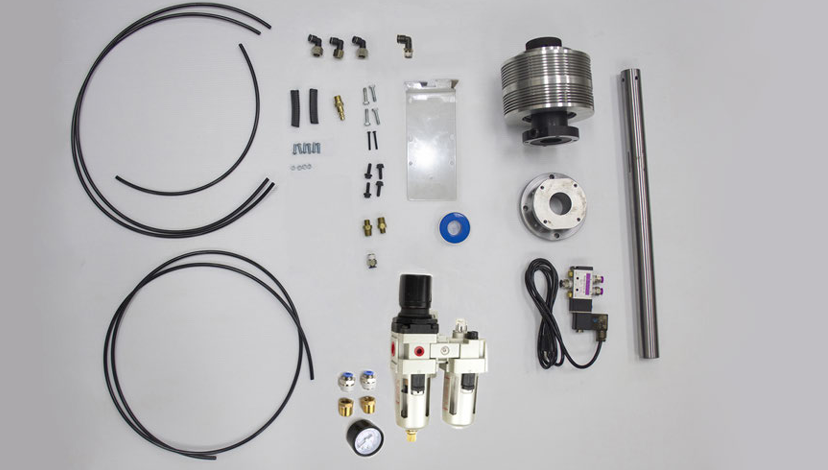
The kit includes the items as shown in the following image.
|
Quantity |
Description |
|
1 |
Adapter Spacer (PN 38253) |
|
1 |
Anti-Rotation Bracket (PN 38278) |
|
4 |
Bolt, Hex Flange, M6 × 1 - 20 (PN 31779) |
|
1 |
Draw Tube (PN 38362) |
|
2 |
Edge Trim (PN 34618) |
|
3 |
Fitting, Elbow, 1/4 in. Tube - 1/4 in. NPT (Female) (PN 31990) |
|
1 |
|
|
2 |
NPT Reducer (PN 38689) |
|
4 |
Nut, Hex, M5 × 0.8 (PN 31201) |
|
1 |
Pneumatic Cylinder |
|
2 |
Screw, Button Head Cap, M4 × 0.7 - 30 (PN 38359) |
|
6 |
Screw, Button Head Cap, M5 × 0.8 - 16 (PN 38360) |
|
4 |
Screw, Hex, M6 × 1 - 25 (PN 32371) |
|
1 |
Solenoid Assembly |
|
1 |
Thread Seal Tape (PN 37508) |
|
4 |
Tube, 1/4 in. OD, Nylon (PN 31457) |
NOTE: If any of these items are missing, we can help. Create a support ticket with Tormach Technical Support at tormach.com/how-to-submit-a-support-ticket for guidance on how to proceed.
Required Tools
Before you begin, make sure you have the following tools and items:
-
3/16-in. hex wrench
-
7/32-in. drill bit
-
9/16-in. box-end wrench
-
11/16-in. box-end wrench
-
2.5 mm hex wrench
-
3 mm hex wrench
-
7 mm wrench
-
8 mm wrench
-
10 mm wrench
-
Dead-blow hammers, two (or similar)
-
Electric drill
-
Machinist stone (or similar)
-
Magnetic dial indicator
-
Marker
-
Phillips screwdriver
-
Safety glasses
Install the Automatic Collet Closer Kit for 15L Slant-PRO
Complete the following steps in the order listed:
Assemble the Pneumatic Cylinder
-
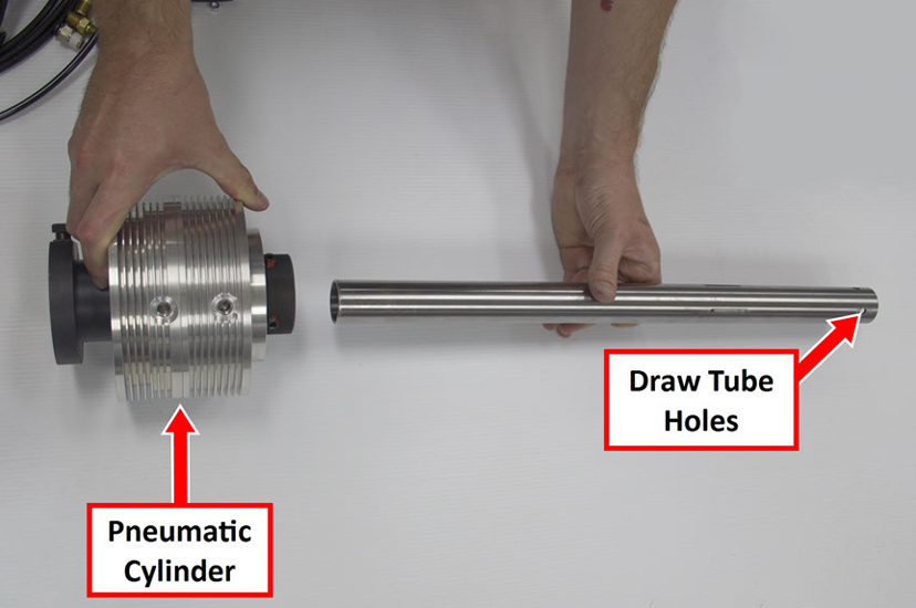
Find the draw tube provided. One end of the draw tube has four holes, which are used to secure the draw tube to the pneumatic cylinder.
-
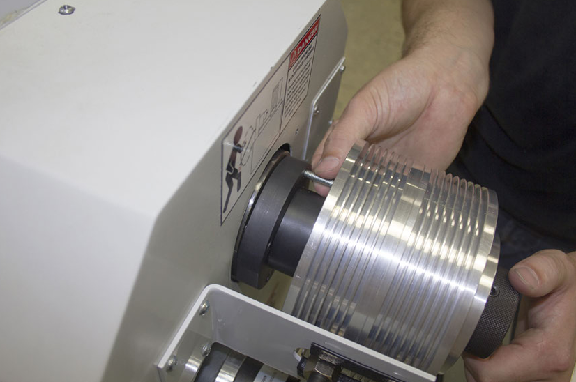
Assemble the draw tube with the pneumatic cylinder so that the draw tube’s holes are furthest away from the pneumatic cylinder, as shown in the following image.
-
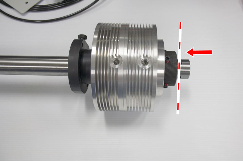
Put the draw tube through the pneumatic cylinder until the end of the draw tube is flush with the end of the pneumatic cylinder.
-
Use a 3/16-in. hex wrench to tighten the four set screws on the pneumatic cylinder that are aligned with the four holes on the draw tube.
The draw tube is now secured in place. -
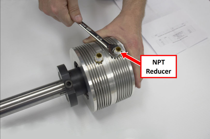
Find the two NPT reducers provided. Wrap the threads on both ends of the NPT reducers with thread seal tape.
-
Install two NPT reducers on the pneumatic cylinder with a 9/16-in. hex wrench.
-
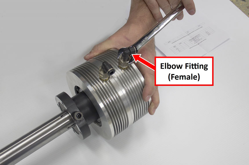
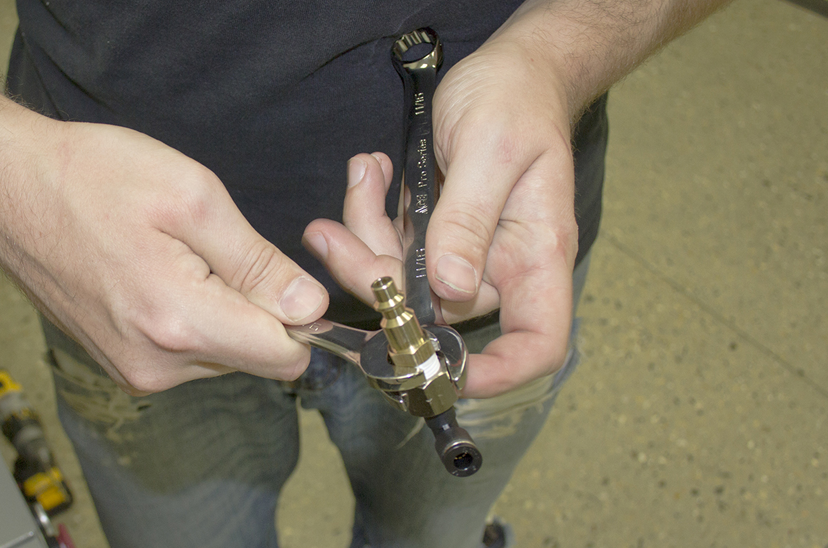
Install two elbow fittings (female) to the NPT reducers with an 11/16-inch wrench.
-
Set aside the pneumatic cylinder assembly for later installation.
Remove the Belt Guard Cover
-
Power off the machine and the PathPilot controller.
-
Push in the machine's red Emergency Stop button, which removes power to motion control.
-
From the PathPilot interface, select Exit.
-
Turn the Main Disconnect switch to OFF on the side of the electrical cabinet.
-
-
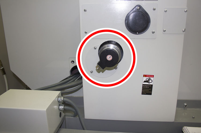
Identify the rotary encoder on the belt guard cover.
-
Disconnect the power connector from the rotary encoder.
-
Identify the encoder cover below the rotary encoder.
-
Remove the encoder cover's three screws with a Phillips screwdriver, and set aside the encoder cover and its screws
-
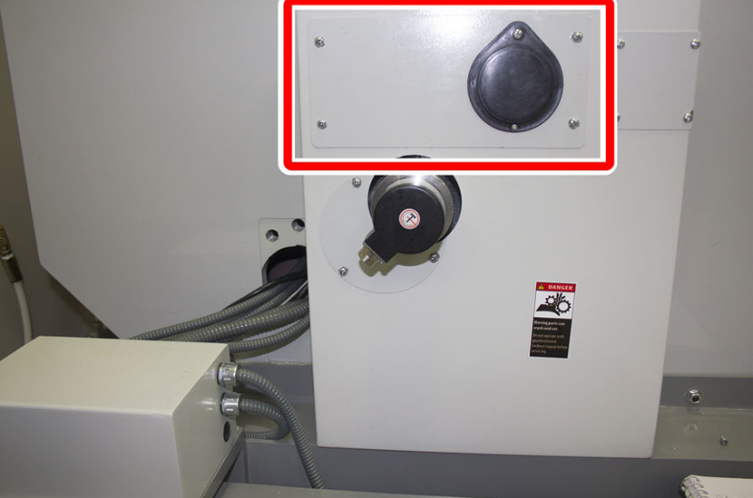
Identify the spindle bore cover above the rotary encoder.
-
Remove the spindle bore cover's screws with a Phillips screwdriver, and discard the spindle bore cover and its screws.
-
Remove the five screws that secure the belt guard cover to the enclosure and the stand with a Phillips screwdriver, and set aside the belt guard cover and its screws.
Install the Anti-Rotation Bracket
This procedure gives instructions to drill two holes in the belt guard cover to use for the anti-rotation bracket provided. To do so, you must first identify the hole locations by temporarily installing the anti-rotation bracket.
-
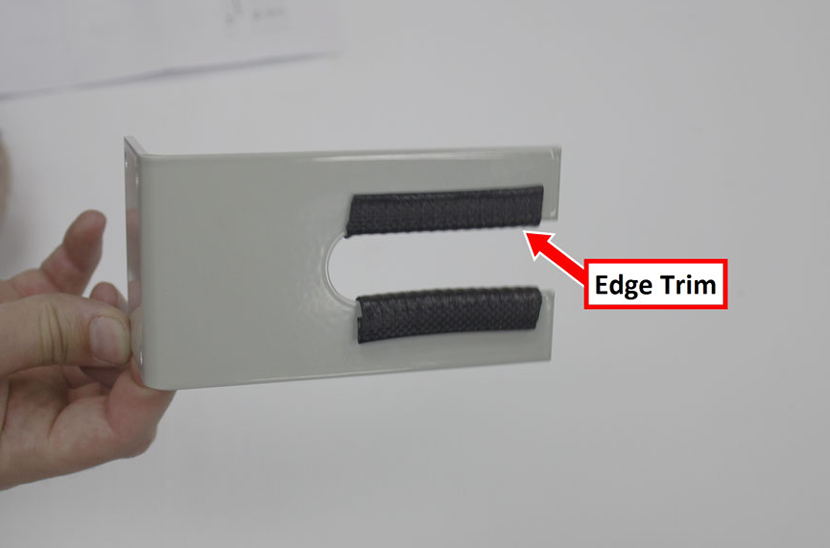
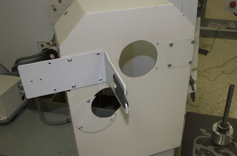
Slide two pieces of edge trim (provided) on the anti-rotation bracket, as shown in the following image.
-
Use two M5 × 0.8 - 16 button head cap screws to temporarily attach the anti-rotation bracket to the belt guard cover, as shown in the following image. Verify that the screws are centered within the slots on the anti-rotation bracket.
-
Use a marker to indicate hole locations on the belt guard cover: Put one mark in the center of each open slot on the anti-rotation bracket.
-
Remove the two M5 × 0.8 - 16 button head cap screws and the anti-rotation bracket.
-
Set aside the anti-rotation bracket and its screws.
-
Drill holes in the two marked locations on the belt guard cover with a #1 drill bit.
-
Install the anti-rotation bracket on the belt guard cover: Use four M5 × 0.8 - 16 button head cap screws and four M5 × 0.8 hex nuts.
Install the Adapter Spacer
-
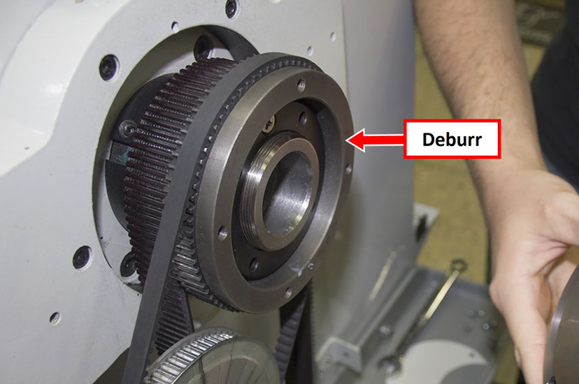
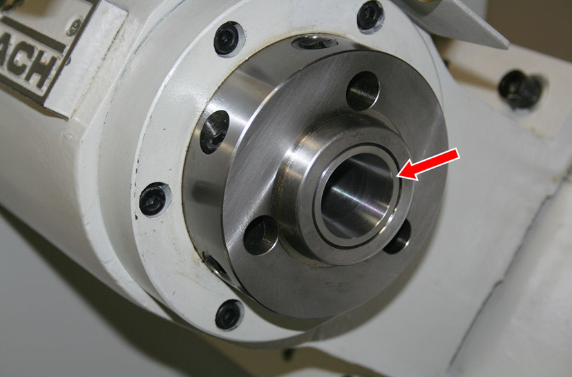
Remove any burrs on the face of the spindle pulley with a machinist's stone. Burrs could cause runout.
-
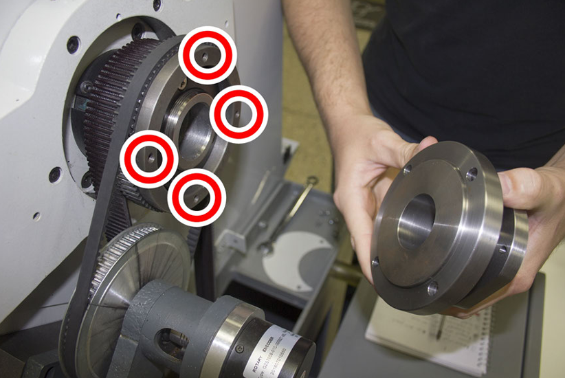
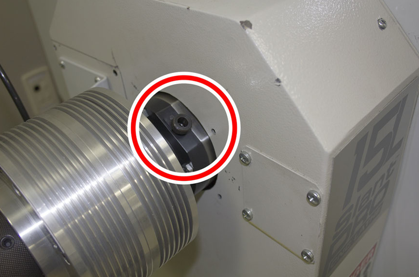
Identify the four pilot holes on the spindle pulley as shown in the following image.
-
Align the four pilot holes on the spindle pulley with the four holes on the adapter spacer.
-
Use a 10 mm wrench and four M6 × 1 - 20 flanged hex bolts to attach the adapter spacer to the spindle pulley.
Re-Install the Belt Guard Cover
-
Find the belt guard cover and its five screws that you set aside earlier.
-
Attach the belt guard cover to the left side of the lathe with a Phillips screwdriver.
-
Find the encoder cover and its three screws that you set aside earlier.
-
Attach the encoder cover to the belt guard cover with a Phillips screwdriver.
-
Connect the power connector to the rotary encoder.
Install the Pneumatic Cylinder Assembly
-
Find the pneumatic cylinder assembly that you set aside in "Assemble the Pneumatic Cylinder" (page 4).
-
Slowly slide the assembly into the spindle while verifying that its fittings slide into the anti-rotation bracket.
-
Identify the thumb screw on the pneumatic cylinder assembly.
-
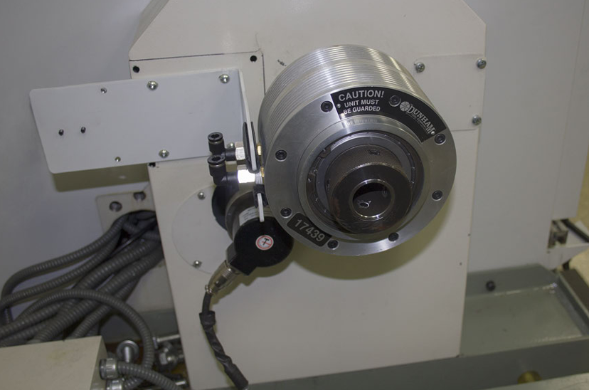
Verify that the thumb screw is aligned with the flat edge on the adapter spacer, as shown in the following image.
-
Use four M6 × 1 - 25 hex head screws to tighten by hand the pneumatic cylinder assembly to the adapter spacer. Verify that the screws are tight, but not tightened completely.
-
Loosen the thumb screw on the pneumatic cylinder assembly. Loosening the thumb screw allows the draw tube to rotate separately from the spindle so that you can thread a collet into the draw tube.
-
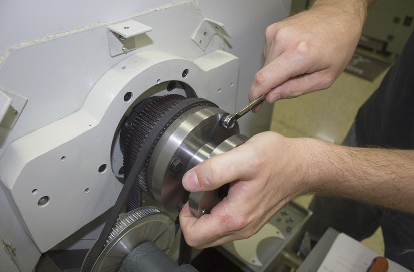
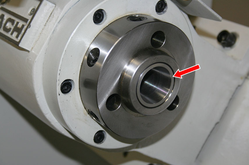
Verify that a 5C insert is installed in the spindle, as shown in the following image.
-
Install a collet into the 5C insert. You must rotate the collet until its groove aligns in the 5C insert.

-
Put a piece of stock into the collet.
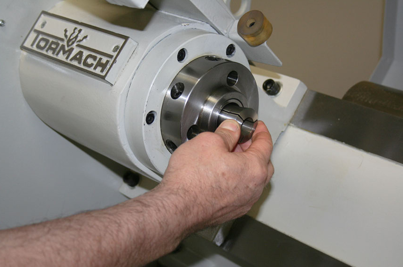
-
Hold the collet with one hand and then, from the pneumatic cylinder, use your other hand to turn the draw tube handle.
-
Continue to thread the collet on the draw tube until it is completely threaded.
-
Tighten the thumb screw on the pneumatic cylinder assembly.
-
To prevent the draw tube from turning during operation, you must make sure that the thumb screw is engaged in the draw tube: Turn the draw tube handle counterclockwise until the thumb screw clicks into one of four slots on the draw tube.
The draw tube is now locked into place.
Make Air Connections
To verify that the air to the solenoid is dry, filtered, and regulated, use the (provided) FRL Filter-Regulator-Lubricator (PN 38829).
NOTE: For an air routing diagram for reference, go to "Pneumatic Schematic".
-
Use two M4 × 0.7 - 30 button head cap screws to attach the solenoid behind the anti-rotation plate, as shown in the following image. Verify that the side with two ports is pointing up.
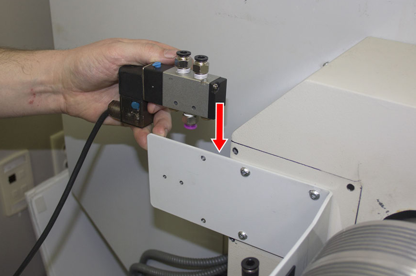
-
Connect the power cord on the solenoid to the outlet marked Closer on the power connection panel.
-
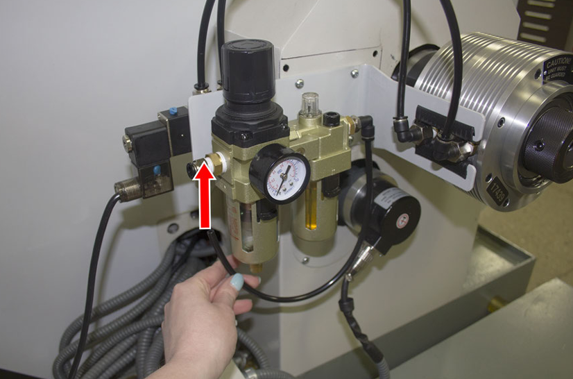
Attach the FRL Filter-Regulator-Lubricator in front of the anti-rotation bracket with one M5 × 0.8 - 16 button head cap screw, as shown in the following image.
NOTE: For setup and operating instructions, see the documentation for the FRL Filter-Regulator-Lubricator (PN 38829).
-
Use the medium-length air tubes provided to make air connections in the following order:
-
Connect one end of each medium-length air tube to each elbow fitting on the pneumatic cylinder.
-
Put the medium-length air tube from the elbow fitting closest to the belt guard cover into port A on the solenoid.
-
Put the medium-length air tube from the elbow fitting furthest from the belt guard cover into port B on the solenoid.
-
-
Connect one end of the shortest air tube provided into port P on the solenoid.
-
Connect the loose end of the shortest air tube to the output port on the FRL Filter-Regulator-Lubricator.
-
Wrap the threads of the quick-connect fitting provided with thread seal tape.
-
Use one 9/16-in. wrench and one 11/16-in. wrench to install the quick-connect fitting into an elbow fitting.
-
Connect one end of the longest air tube provided to the elbow fitting.
-
Connect the loose end of the longest air tube to the input port on the FRL Filter-Regulator-Lubricator.
-
Connect the quick-connect fitting to the air compressor.
Align the Automatic Collet Closer Kit with the Spindle
-
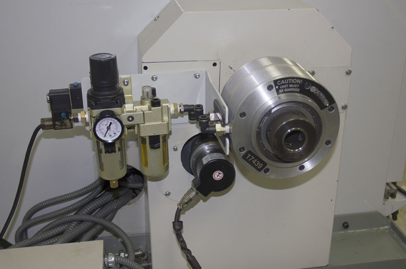
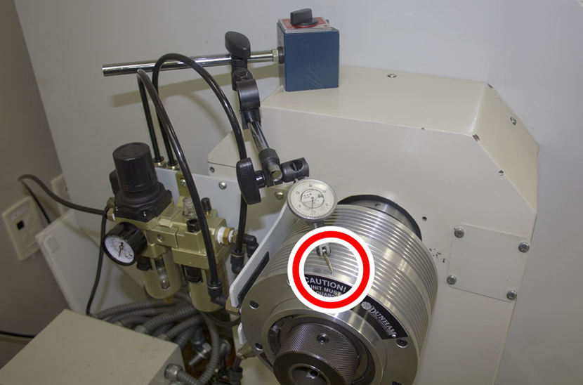
Put the base of a magnetic dial indicator on the top of the belt guard cover. Verify that the magnetic dial indicator touches the aluminum of the pneumatic cylinder furthest away from the belt guard cover, as shown in the following image.
-
Rotate the spindle clockwise. On the magnetic dial indicator, the needle rises and falls. Continue to rotate the spindle until the needle reaches the highest point on the magnetic dial indicator.
-
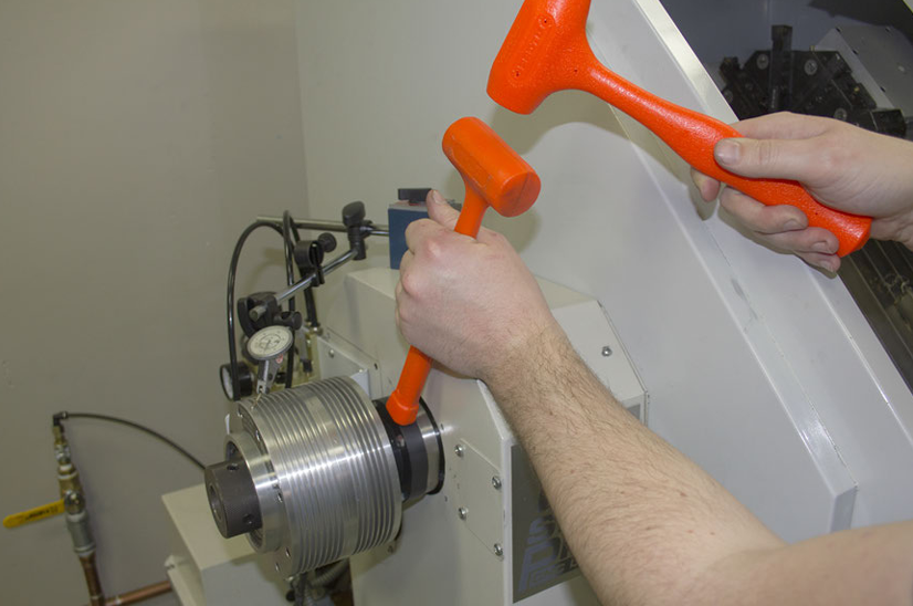
Gently tap the mounting flange with two dead-blow hammers, as shown in the following image.
-
Rotate the spindle clockwise until the needle again reaches the highest point on the magnetic dial indicator.
-
Repeat Steps 2 through 4 until the spindle runout is less than 0.002 in.
NOTE: If the reading on the magnetic dial indicator remains the same after you tap the mounting flange with the dead-blow hammer, loosen the four M6 × 1 - 25 hex head screws, and repeat Steps 3 through 4.
-
Tighten the four M6 × 1 - 25 hex head screws on the mounting flange with a 10 mm wrench.
-
Power on the machine and the PathPilot controller.
-
Turn the Main Disconnect switch to ON on the side of the electrical cabinet.
-
Twist out the machine's red Emergency Stop button, which enables movement to the machine axes and the spindle.
-
Press the Start button.
-
You have completed installing the Automatic Collet Closer Kit for 15L Slant-PRO. For operating instructions, go to "Operation”.
Operation
WARNING! Operator Knowledge: You and all other operators must read and understand the 15L Slant-PRO operator manual before installing, using, or maintaining the machine.
NOTE: The Automatic Collet Closer Kit requires PathPilot v2.2.2 or later. If you haven't yet done so, download and install the latest version of PathPilot.
Automatic Operation
-
Use G-code to program the collet closer to open and close:
-
M10 opens the collet closer.
-
M11 closes the collet closer.
-
Manual Operation
-
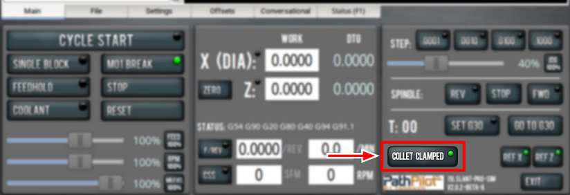
From the PathPilot interface, select Collet Clamped to toggle the button's green light on and off.
-
When the Collet Clamped button's green light is on, the collet is in the closed (clamped) position.
-
When the Collet Clamped button's green light is off, the collet is in the open (unclamped) position.
-
Switch Between ID and OD Clamping
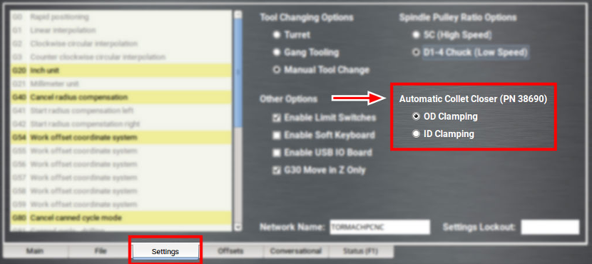
To switch between clamping the inside diameter and the outside diameter of a workpiece:
-
From the PathPilot interface, on the Settings tab, select either the ID Clamping or the OD Clamping option.
Change the Collet
-
From the PathPilot interface, select Collet Clamped to toggle the button's light off.
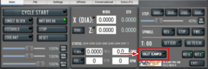
The collet closer is now in the open position.
-
Loosen the thumb screw on the pneumatic cylinder assembly. Loosening the thumb screw allows the draw tube to rotate separately from the spindle so that you can thread a collet into the draw tube.
-
Verify that a 5C insert is installed in the spindle, as shown in the following image.
-
Install a collet into the 5C insert. You must rotate the collet until its groove aligns in the 5C insert.
-
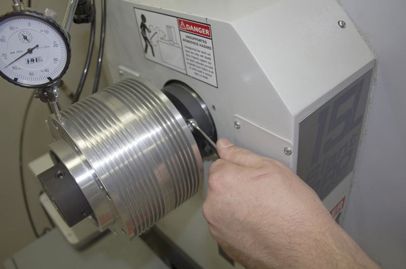
Hold the collet with one hand and then, from the pneumatic cylinder, use your other hand to turn the draw tube handle.
-
Continue to thread the collet on the draw tube until it is completely threaded.
-
Tighten the thumb screw on the pneumatic cylinder assembly.
-
To prevent the draw tube from turning during operation, you must make sure that the thumb screw is engaged in the draw tube: Turn the draw tube handle counterclockwise until the thumb screw clicks into one of four slots on the draw tube.
The draw tube is now locked into place, and the collet is ready for the workpiece.
Adjust the Holding Force
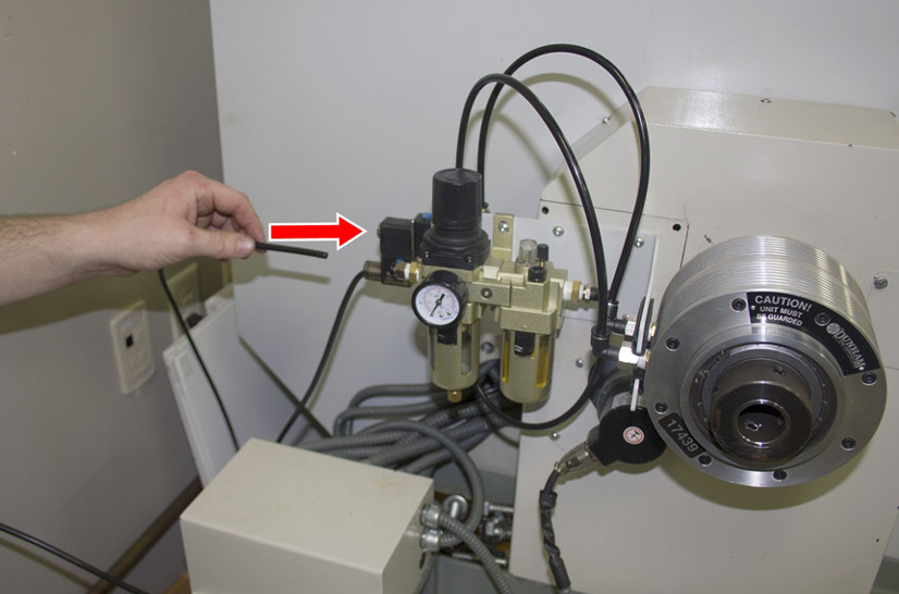
If needed, you can adjust the holding force using the pressure regulator:
-
Increase the pressure to increase the holding force.
-
Decrease the pressure to decrease the holding force.
NOTE: Refer to "Specifications" for information on holding force limits.
We recommend you begin with 40 psi, and then gradually increase the pressure until the part is sufficiently held.
Specifications
|
Maximum Continuous rpm |
3600 rpm |
|
Maximum psi |
100 psi |
|
Pull Force |
1600 lb at 100 psi |
|
Push Force |
600 lb at 100 psi |
Pneumatic Schematic
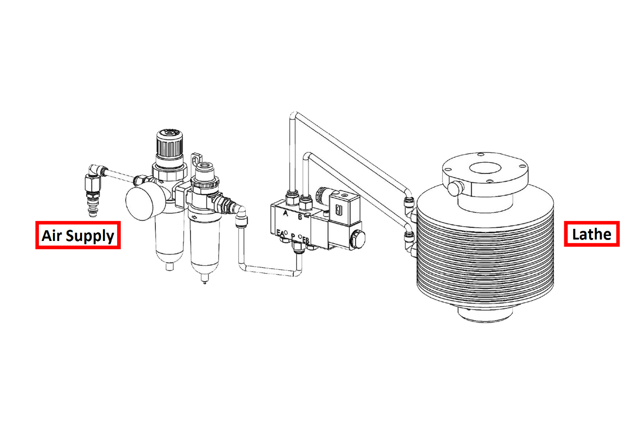
To view a PDF version of your manual, go to Tormach document TD10534.
If you have additional questions, we can help. Create a support ticket with Tormach Technical Support at tormach.com/how-to-submit-a-support-ticket for guidance on how to proceed.