Product Identification:
Turret Installation Kit (PN 33273)
Purpose:
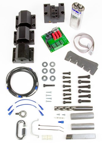
This document details installation of the Eight-position Turret on the 15L Slant-PRO lathe. There are seven sections to this installation: Turret Mechanical Install, Turret Electrical Install, Turret Alignment, Lubrication Procedure, Boring Bar Holder Install, OD Turning/Facing Tool Holder Install, and Tool Holder/ Tool Extraction. The turret must be installed prior to lathe enclosure installation. Check to ensure you have all the turret kit parts:
|
Turret Installation Kit (PN 33273) |
Qty. |
Part Number (PN) |
|
Eight-position Turret |
1 |
33201 |
|
Turret Control Board |
1 |
32785 |
|
Shim Kit |
1 |
33324 |
|
Ribbon Cable |
1 |
32878 |
|
Capacitor |
1 |
32870 |
|
Capacitor Bracket |
1 |
32871 |
|
M4 x 10 mm Phillips Screws |
2 |
30537 |
|
M4 x 10 mm Spacers |
4 |
34626 |
|
M4 x 20 mm Phillips Screws |
4 |
34627 |
|
Turret Installation Wiring Kit |
1 |
35141 |
|
Test Pieces |
2 |
34718 |
|
Cemented Carbide OD Turning Tool |
1 |
34824 |
|
3/4” Center Cut End Mill |
1 |
35146 |
|
M8 x 25 mm Socket Head Cap Screws |
8 |
34635 |
|
M8 x 40 mm Extraction Bolt |
1 |
34831 |
|
M10 x 40 mm Socket Head Cap Screws |
6 |
34621 |
|
M10 Flat Washers |
6 |
32473 |
|
Eye Bolt |
1 |
— |
|
Shackle (C-shaped or U-shaped) |
1 |
— |
|
OD Turning/Facing Tool Holder |
1 |
33238 |
|
Boring Bar Holders |
3 |
33237 |
|
4” Cable Ties w/ Mounting Tabs |
2 |
— |
|
Coolant Elbow (may be installed) |
1 |
— |
|
Turret Oil (not shown) |
32 oz. |
35260 |
NOTE: If any of these items are missing, contact Tormach Customer Service for a replacement at (608) 849-8381.
Required Tools
-
Machinist Stone or similar
-
Dial Indicator (PN 31947)
-
Micrometer/Calipers
-
Phillips Screw Driver
-
Socket Set/Wrench
-
Engine Hoist or similar
-
Metric Hex Driver Set
Turret Mechanical Install
-
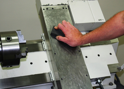
Prior to turret installation, clean the lathe’s slant bed with a machinist stone or similar (see Figure 1). Surface should be free of burrs or debris. Repeat the same procedure for the bottom of the turret.
![]()
-
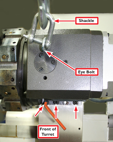
Screw the Eye Bolt tightly into the turret and attach Shackle (if needed) as shown in Figure 2; use lift system to raise turret above lathe.
-
Screw three M10 x 40 mm Socket Head Cap Screws (each with one flat washer) two-thirds of the way into the lathe’s slant bed as shown in Figure 2. Use lift system to lower turret onto three screws and snug down with hex wrench.
IMPORTANT: Keep turret attached to lift system until instructed to remove.
-
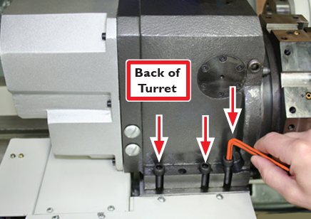
Secure the back side of the turret by screwing three cap screws (each with one flat washer) into the back of the slant bed; snug down with hex wrench (see Figure 3).
-
When both the front and back of the turret are secured, disconnect the lift system from the turret’s Eye Bolt (refer to Figure 2); remove Eyebolt.
-
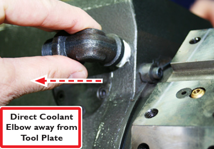
If not already installed, locate the included Coolant Elbow; wrap elbow threads with plumber’s tape and screw securely into top of turret (see Figure 4). Coolant elbow must be directed away from turret Tool Plate as shown in Figure 4; attach lathe’s coolant hose to elbow.
-
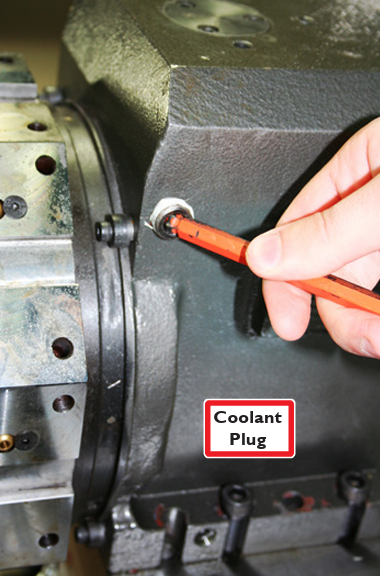
On the opposite side of the turret, remove the Coolant Plug; seal threads with plumber’s tape and screw securely back into turret (see Figure 5).
Turret Electrical Install
-
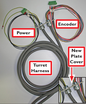
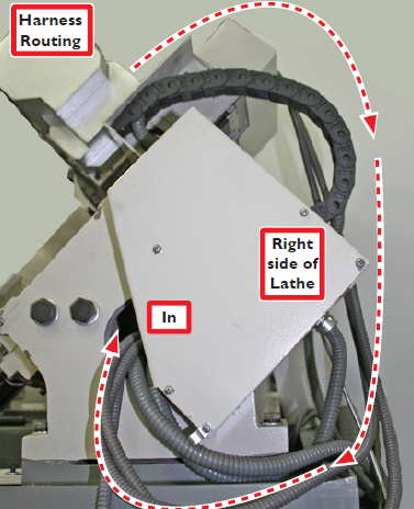
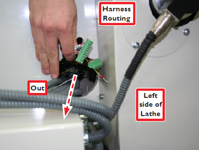
Route the Turret Harness by draping it over back of lathe and around right side (see Figures 6 and 7). Harness must be free from entanglement through full motion of lathe.
-
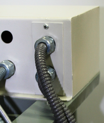
Route harness through lathe casting as shown in Figure 7 and Figure 8.
-
Pull harness through far enough that the New Cover Plate reaches the Cabinet-top Box (see Figure 14).
![]()
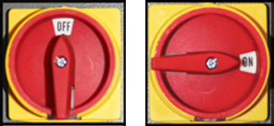
Power off machine according to Power Off/On Procedure.
Power Off/On Procedure
|
Power Off |
|
|
|
|
3.Turn Main Disconnect Off |
|
Power On |
1.Turn Main Disconnect On |
|
|
|
|
|
-
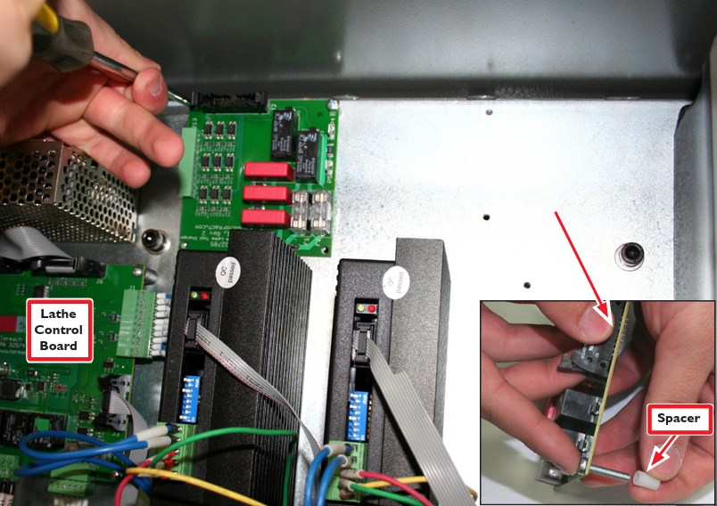
Open the electrical cabinet on the side of the lathe. Insert four M4 x 20 mm Phillips Screws through the four corner holes in the Turret Control Board; slide M4 x 10 mm Spacers onto the four screws as shown in Figure 9 inset.
-
Attach Turret Control Board to back wall of electrical cabinet via four pre-drilled/tapped holes (see Figure 9).
-
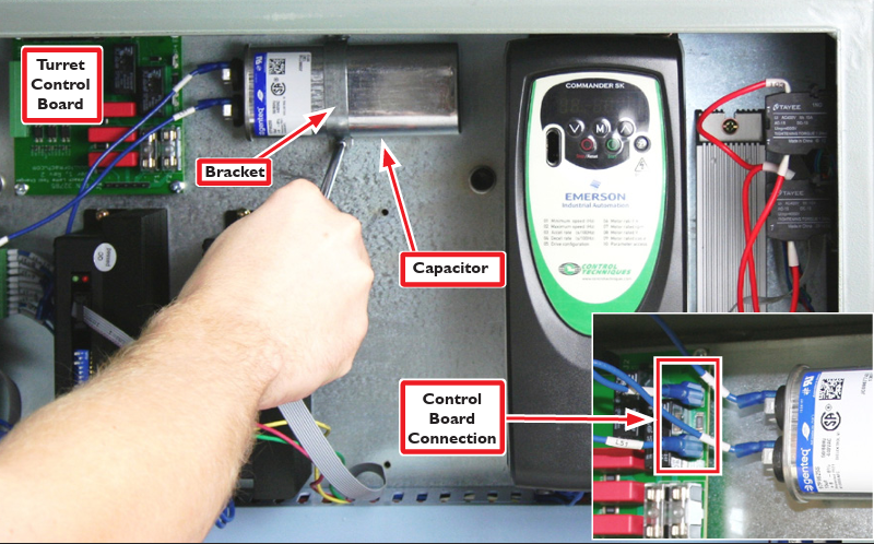
Locate and connect two ends of the turret capacitor wires (blue L51 and L52) to either terminal on the Capacitor (see Figure 10).
-
Using the Capacitor Bracket and two M4 x 10 mm Phillips Screws, attach the Capacitor to the back of the electrical panel (see Figure 10); holes are pre-drilled and tapped.
-
Connect the other two loose ends of turret capacitor wires (blue L51 and L52) to either P4 or P5 terminals on the Turret Control Board as shown in Figure 10 inset. The Capacitor is non-polar, so there is no wrong way to connect these.
-
To begin routing the Power and Encoder ends of the harness into the electrical cabinet, remove cover plate from the Cabinet-top Box (see Figure 11); set the two mounting screws aside.
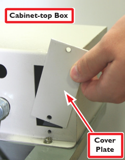
-
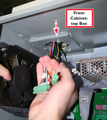
Carefully feed Turret Power and Encoder wires down into Cabinet-top Box (see Figure 14). Pull wires through into the electrical cabinet far enough to reach all connections.
NOTE: Lathe serial numbers 10025 and lower do not have a removable cover plate (see Figure 11). To allow Power and Encoder wire access to the electrical cabinet, lathe owners with these serial numbers must carefully remove the cover of the Cabinet-top Box and drill two 5/8” holes in the side of the box. Be careful not to damage wires when drilling or allow metal shavings to enter electrical cabinet. Once holes are drilled, remove connector blocks and conduit fitting nuts from harness; discard plate provided with kit. Secure conduit fitting nuts inside Cabinet-top Box. Reconnect connector blocks as shown in Figure 15.
-
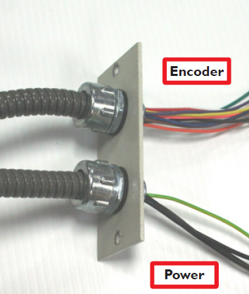
Connect new cover plate/harness assembly as shown in Figures 12 and 13; secure with two screws set aside in step 6.
-
Identify the Turret Harness’ Power Connector Block and Encoder Connector Block (see Figure 16).
-
Check to ensure the Encoder Connector Block wires are in sequential order (see Figure 15).
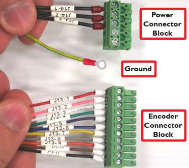
-
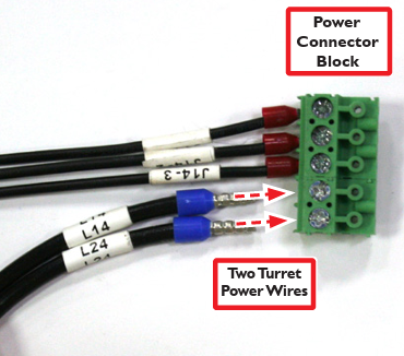
Locate the two black Turret Power Wires (included), L14 and L24 (see Figure 16).
-
Loosen lock screws for two open positions in the Power Connector Block and connect wires as shown in Figure 16; re-tighten screws snugly.
-
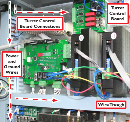
Route connections running to the Turret Control Board as shown in (see Figure 17).
-
Power and ground wires should be routed through the wire troughs (see Figure 17).
-
Locate the CI contactor in the electrical cabinet and loosen L14 terminal’s lock screw (see Figure 18).
-
Piggyback the L14 spade terminal onto the existing L14 connection CI contactor as shown in Figure 18.
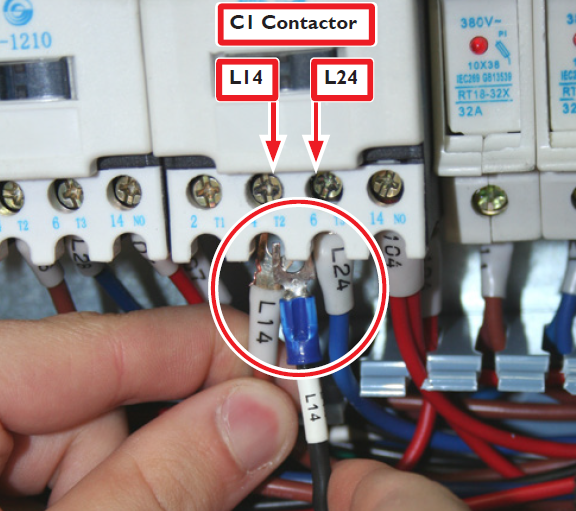
-
Re-tighten L14 terminal lock screw, securing both terminal wires.
-
Repeat steps 15-17 for the other power wire (L24); piggyback on existing L24 connection on the C1 Contactor.
-
Reference Figure 20 when making the four Turret Control Board connections.
IMPORTANT: Do not connect the items outlined in Figure 20 at this time. This image shown is for reference purposes only. The detailed connection procedure is explained in the following steps.
-
Plug the Encoder Connector Block into the Turret Control Board as shown in Figure 20.
-
Plug the Power Connector Block onto the Turret Control Board as shown in Figure 19.
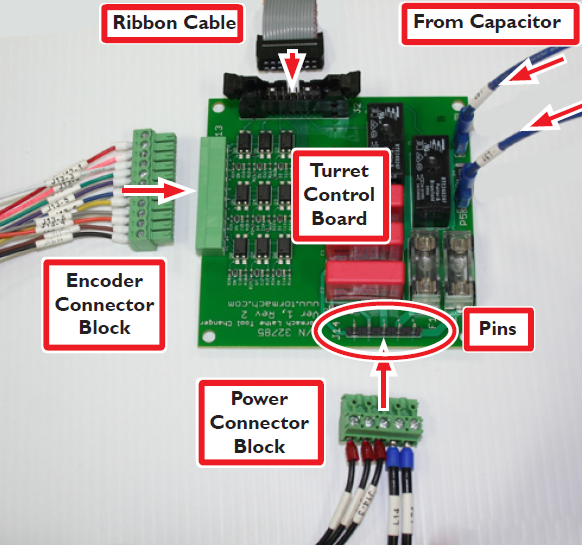
IMPORTANT: Proper alignment/orientation of Power Connector Block into the Turret Control Board is crucial to avoid damage (see Figure 20).
-
Locate the Turret Ground wire and connect to any terminal opening in the green section of the Ground Terminal Block (see Figure 21).
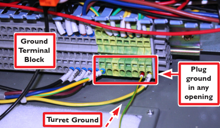
NOTE: If Ground Wire does not reach Ground Terminal Block, screw on extra length of ground wire (included).
-
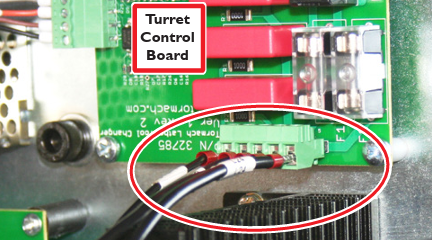
Connect one end of the Ribbon Cable (included) to Turret Control Board as shown in Figure 19.
-
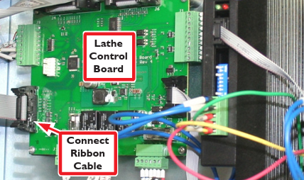
Route the other end of the Ribbon Cable through the wire trough and connect to the Lathe Control Board as shown in Figure 22.
-
Secure all connections running to Turret Control Board (see Figure 17) to pre-drilled holes with 4” Cable Ties/Mounting Tabs.
-
Reinstall any wire trough covers that were removed.
IMPORTANT: The turret must be installed prior to lathe enclosure installation. However, the enclosure must be installed prior to proceeding with Turret Alignment (below). For detailed lathe enclosure installation instructions, please refer to the following technical document: 15L Gen 2 Enclosure.
-
Power on machine according to the Power Off/On Procedure detailed in the Turret Electrical Install section of this document.
-
Test the turret to ensure it is functioning properly. Do this by first indexing the turret through all positions (refer to 15L Slant-PRO lathe manual). If the turret does not lock into place – or errors out – refer to the trouble shooting guide at the end of this document. A simple test to determine whether the turret is locking correctly would be to insert a broom handle (or similar lever) in each turret pocket and pry both up and down. Upon application of light pressure, there should ne any motion of the turret dial.
IMPORTANT: Before attempting the following procedures, Tormach recommends the operator become familiar with the lathe control system (per the operator manual). This will make alignment go quicker and minimize the possibility of machine damage.
Lubrication Procedure
IMPORTANT: Add approximately 3/4 of 32 oz. bottle of Turret Oil (included) prior to first use.
-
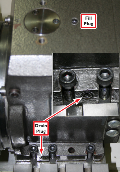
Remove oil sump Drain Plug (see Figure 23); drain and discard oil; replace Drain Plug.
-
Remove oil Fill Plug (see Figure 23).
-
Using a funnel, add approximately 3/4 of 32 oz. bottle of Turret Oil (included) or 28 oz. of ISO VG46 equivalent; replace oil Fill Plug.
-
To aid in oil distribution, rotate turret through two full rotations.
IMPORTANT: Replace Turret Oil every six months or sooner as needed.
Turret Alignment
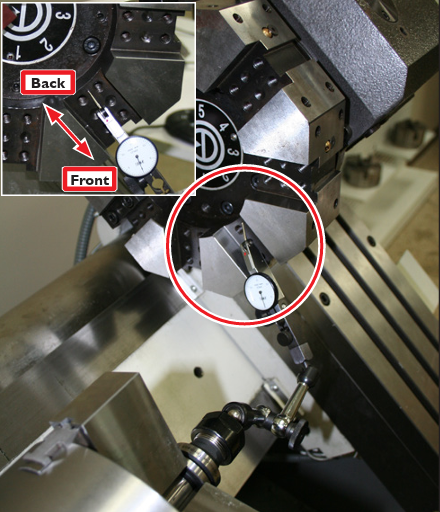
Using a dial indicator, ensure the cutting position tool pocket (i.e., pocket slated for tool insertion) is level to the X axis (see Figure 24).
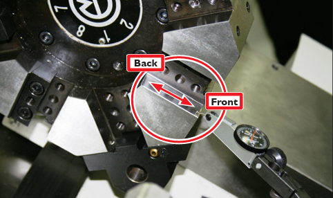
Do this by zeroing the dial indicator at the back of the pocket and then jogging to the front of the pocket. Use this measurement to calculate the amount of level adjustment required (by adding or removing shims). For example, if the dial indicator reads -.004”, divide that figure by two, which equals .002” – the amount of shim correction required for the front of the turret. If the dial indicator reads zero from back to front, no extra shimming is required (for this step); proceed with step 2. Jot down this number for use in step 5. Also refer to the Calculating Shim Adjustments table (below).
|
Calculating Shim Adjustments |
|
|
- reading |
If dial indicator jog results in minus reading, then add shims to the front of the turret |
|
+ reading |
If dial indicator jog results in plus reading, then remove shims to the front of the turret |
-
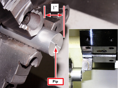
Insert an aluminum Test Piece (included) into lathe spindle, leaving 1” protruding; tighten spindle (see Figure 25).
-
Position tool in an upward facing orientation as shown in Figure 25 inset.
-
Face the Test Piece @ 500 RPM until pip forms at center of piece (see Figure 25).
-
Measure pip with micrometer and divide measurement by two. For example, if the pip measures .022”, divide that number by two which equals .011”. This is the amount of shim correction required.
-
To adjust alignment, combine the pip measurement and the level measurement (from Turret Alignment step 1). For example, .002” + .011” = .013”. This is the shim thickness required to be inserted under the front of the turret. The .011” number represents the shim thickness required to be placed under the back of the turret.
-
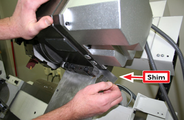
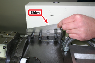
Add shims (from the included Shim Kit) to the front and back of the turret after loosening all six M10 x 40 mm Socket Head Cap Screws (see Figures 26 and 27).
-
To create gap necessary to add shims to front of turret, push forward on it (see Figure 26); insert required shim(s).
NOTE: For easy insertion of shims use lift mechanism as outlined in Turret Mechanical Install section of this document.
IMPORTANT: Do not use pry bar or any similar device to create a gap between turret and lathe bed as mounting surfaces may be damaged.
-
To add shims to back of turret, pull backward on it to create a gap; insert the required shim(s) as shown in Figure 27.
-
Repeat steps 1 through 6 until the cutting position tool pocket (i.e., the pocket that you are going to insert tool in) is level to the X axis.
-
Once adjustment is complete, tighten down all six Socket Head Cap Screws securely.
-
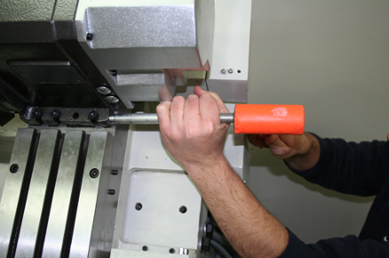
To ensure the tool pocket is parallel to the spindle, run the dial indicator back to front in the tool pocket (see Figure 28). If, for example, the dial indicator reads -.001”, slightly loosen all six Socket Head Cap Screws.
-
Using a piece of wood or aluminum, tap turret with dead-blow hammer (see Figure 29). Repeat until tool pocket is parallel to spindle.
-
Once adjustment is complete, tighten down all six Socket Head Cap Screws securely.
Boring Bar Holder Installation
-
Identify tool pocket to be used for Boring Bar Holder.
-
Using a hex wrench, loosen Coolant Lock Screw; insert a second wrench into Coolant Nozzle to aim coolant flow as needed (see Figure 30).
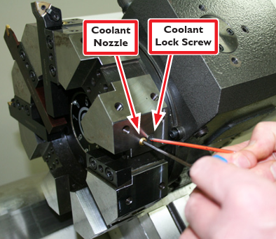
NOTE: Coolant Nozzle must be directed to allow coolant flow through Boring Bar Holder.
-
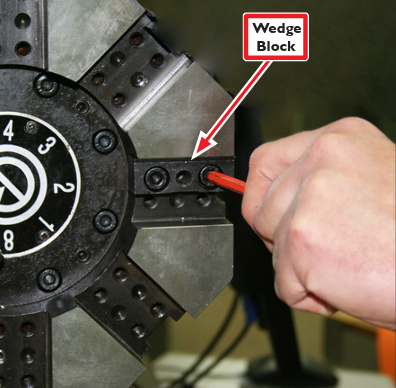
Remove Wedge Block from tool pocket as shown in Figure 31; retain screws to mount boring block.
-
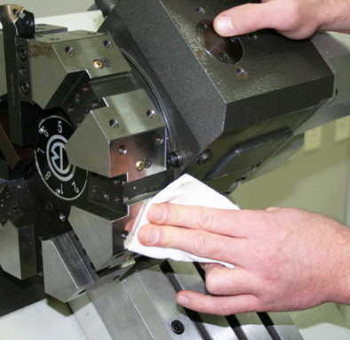
Inspect surfaces of both turret and Boring Bar Holder; remove burrs, wipe off grit and dirt (see Figure 32). If necessary, use hand-held stone to deburr surface. Spray surfaces with a rust preventative such as WD-40®.
-
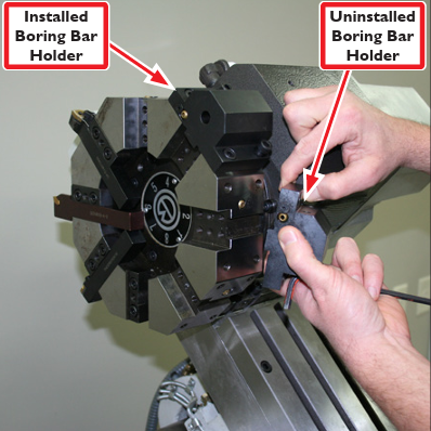
Using four M8 x 25 mm Socket Head Cap Screws, install one of three (included) Boring Bar Holders as shown in Figure 33; tighten snugly.
-
If installed, remove two (tool retaining) Set Screws from Boring Bar Holder as shown in Figure 36; set aside for later use.
-
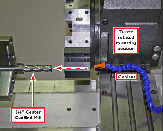
Rotate (or index) turret until Boring Bar Holder is in cutting position (see Figure 34).
-
Install (included) 3/4” Center Cut End Mill into spindle (see Figure 34).
-
Jog mill in X axis to line up spindle with Boring Bar Holder (see Figure 34).
-
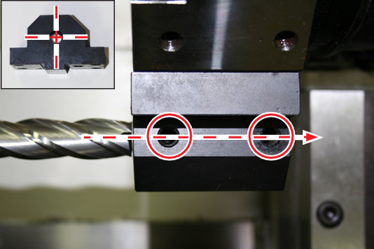
Fine tune alignment of End Mill with lock-down screw holes as shown in Figure 35 and inset.
-
Set jog increment to .001”.
-
While flooding the Boring Bar Holder with Coolant (see Figure 34), slowly jog in Z axis to feed Boring Bar Holder into end mill (see Figure 35 and inset); drill through Boring Bar Holder.
-
Repeat steps 1-11 for two remaining Boring Bar Holders.
-
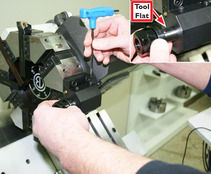
Screw two Set Screws (removed earlier) loosely into Boring Bar Holder and insert 3/4” tool; Tool Flat should face Set Screws. Tighten snugly (see Figure 36 and inset).
OD Turning/Facing Tool Holder Install
-
Remove Wedge Block as shown in Figure 31 (if installed).
-
Inspect surfaces of both turret and OD Turning/ Facing Tool Holder; remove burrs, wipe off grit and dirt (see Figure 32). If necessary, use hand-held stone to deburr surface. Spray surfaces with rust preventative such as WD40®.
-
Using a hex wrench, loosen Coolant Lock Screw; insert a second hex wrench into nozzle to adjust flow direction as needed (see Figure 30). Retighten Coolant Lock Screw snugly.
-
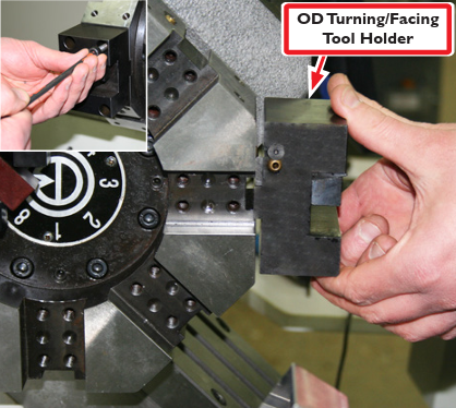
Using four M8 x 30 mm Socket Head Cap Screws, install OD Turning/Facing Tool Holder (see Figure 37); tighten snugly.
Tool Holder/Tool Extraction
-
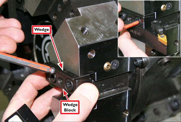
Loosen Wedge Block.
-
Hold Wedge Block while pushing in on Wedge as shown in Figure 38.
-
Insert tool and tighten Wedge Block snugly (see Figure 38 inset).
-
To extract tool, remove two Wedge Block screws; insert M8 x 40 mm Extraction Bolt in center hole as shown in Figure 39.
-
Holding tool with hand, screw in Extraction Bolt until tool comes free.
Turret Set Up: Tool Alignment and Crash Avoidance
Tool alignment pertains to how the cutting edge of the cutting insert is oriented/positioned along the X, Y (tool height), and Z axes. While turret alignment with the axes was addressed earlier in this document, some cutting tools may require additional alignment. A lathe turret allows the mounting of multiple tools for fast, accurate, mid-program tool changes. That said, it’s important to note that when using a CNC lathe there is always the risk of tool crashes – into the work, the spindle head stock, or the chuck. This applies to CNC lathes equipped with turrets as well as gang-mounted tools. Therefore, careful tool and program planning are necessary. Do test runs (cutting air) at decreased feed rates. Take every precaution necessary to avoid a tool crash. Choosing which tool is mounted in which turret position is extremely important. Since operator machining setups vary widely, Tormach is unable to instruct where to mount your tools. This following section is intended to give some general pointers on tool mounting.
![]()
Shimming
Shimming of tools to set tool height and orientation is common in any lathe set up. Shims come in a wide variety of shapes, sizes, materials, and thicknesses. Be sure to have a general shim kit or variety pack available for mounting a variety of tools. Shims typically range in size from .0005” to .01” or larger. Stacking of shims to get the right thickness is not ideal, but not uncommon either.
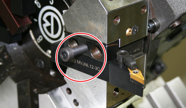
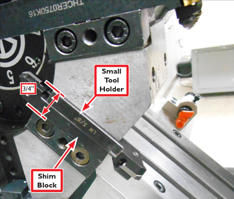
Nominal Tooling Size
Tormach advises ¾” tooling for the turret, but it is possible to use smaller tool holders (see Figure 40). Keep in mind that these must be shimmed so tool tip is in line with the spindle axis.
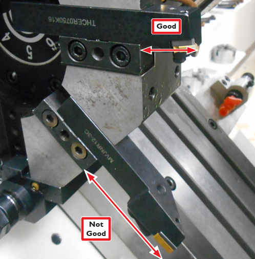
Tooling Length
To reduce vibration and deflection, mount tools with the cutting tip as close to the turret clamp or block as possible (see Figure 41).
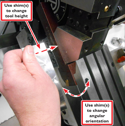
Tool Turret Position Repeatability
While turret operation is fairly accurate and repeatable, it’s impossible to be perfect. During turret installation, earlier in this document, height and alignment were adjusted for one pocket. This resulted in all other pockets being very close to, but not duplicating first pocket height and alignment completely. Since most lathe tools aren’t sensitive to this alignment, being off by, for example, .003”, may not have any measurable impact on a part. Some tools, such as parting tools for example, need to be as close to perfect as possible. We recommend that tools sensitive to alignment be mounted in the first pocket (used for aligning the turret), or be shimmed (up/down, side to side) appropriately (see Figure 42). There is sometimes a trial and error process that occurs to learn where this may or may not be relevant.
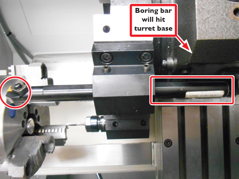
IMPORTANT: Be aware that it is possible for a tool to be mounted out far enough that it could crash into the lathe bed.
IMPORTANT: Some ¾” boring bars can protrude out too far towards the turret base, resulting in a crash during a tool change. To eliminate this issue, cut the boring bar shorter.
Turret Tool Positions
Be aware of the crash potential of all tool positions during use of each tool (see Figure 43). For example when using turret position #1 for a short tool like a tap (that requires turret be very close to the workpiece), be aware of tools in the remaining positions (2-8), as the tap is cutting into the stock.
Issues to consider:
Is the boring bar or a long drill bit (in position #2) going to hit the chuck or head stock? This is a complicated crash scenario to predict. Simply creating a CAM program, inserting the code in the lathe, loading tools, and pushing Cycle Start – without considering where all tools are at all times – can trigger such a crash scenario.
Typically the greatest concern is related to tools oriented parallel to the spindle. For example, if there are large variations in length of tools mounted in boring bar holders, mount the tools as far away from each other as possible.
Sensor Alignment and Adjustment
The Turret has a tool locked sensor that may require adjustment to achieve a complete locking of the turret face after a tool change. Instructions:
-
Power off machine according to the Power Off/ On Procedure detailed in the Turret Electrical Install section of this document.
-
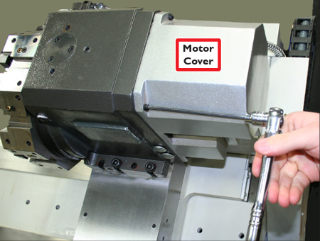
Remove six socket head cap screws attaching the Motor Cover to the back of the Turret (see Figure 44); remove cover.
-
Using a hex wrench, rotate the turret motor in a clockwise direction until the turret moves to a fully-locked position (see Figure 45).
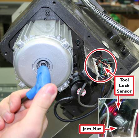
NOTE: Turret is locked when motor is harder to turn.
-
Loosen the Jam Nut on the Tool Lock Sensor (see Figure 45 and inset).
-
Power on machine according to the Power Off/ On Procedure detailed in the Turret Electrical Install section of this document. Press the green Start button on the Operator Panel. At this point the only voltage to the turret is 24 V logic signals, but it’s a good practice to avoid touching any of the exposed wires.
-
With the Turret in the locked position, the red LED on the Tool Lock Sensor should be illuminated.
-
Move the Tool Lock Sensor in (towards the turret body) until the red LED goes out, then back it off by approximately 0.020”.When the turret is locked, the LED should be illuminated. Be sure to test all tool positions.
Troubleshooting
|
Problem |
Solution(s) |
|
Red LED never comes on |
Check power to machine, check ribbon cable from lathe control board to turret control board. |
|
Turret indexes, but never fully locks |
Move tool lock sensor closer to the turret body
Check lubrication; drain and refill per the lubrication instructions. |
|
Turret indexes, but then gets stuck in locked position |
Move tool lock sensor farther away from turret body |
Turret Replacement Parts (not shown in this document)
|
Part Description |
PN |
|
Turret Tool Clamp |
34827 |
|
Turret Motor |
34290 |
|
Turret Encoder |
34302 |
|
Turret Lock Sensor |
34329 |
To view a PDF version of your manual, go to Tormach document TD10307.
If you have additional questions, we can help. Create a support ticket with Tormach Technical Support at tormach.com/how-to-submit-a-support-ticket for guidance on how to proceed.