Purpose:
This document gives instructions to install the eight-position turret on a 15L Slant-PRO lathe.
Product Identification: Turret Kit for 15L Slant-PRO (PN 37335)
|
Quantity |
Description |
|
2 |
4 in. Cable Tie w/ Mounting Tab |
|
4 |
11 in. Cable Tie |
|
3 |
Boring Bar Holder (pre-installed) (PN 37136) |
|
1 |
Capacitor (PN 38460) |
|
1 |
Capacitor Bracket (PN 38749) |
|
1 |
Cemented Carbide OD Turning Tool (PN 34824) |
|
1 |
Coolant Fitting (may be pre-installed) |
|
1 |
Eight-Position Turret (PN 34947) |
|
1 |
Eye Bolt and Shackle (C- or U-Shaped) |
|
1 |
IDC Ribbon Cable Assembly, 18 in. Long, 16 Pin (PN 51540) |
|
1 |
OD Turning/Facing Tool Holder (pre-installed) (PN 37137) |
|
4 |
Screw, Button Head Cap, M4 × 0.7 - 8, Stainless Steel (PN 50838) |
|
4 |
Screw, Phillips, M4 × 20 mm (PN 34627) |
|
6 |
Screw, Socket Head Cap, M10 × 30 mm (PN 34621) |
|
1 |
Shim Kit (PN 33324) |
|
1 |
Spare Motor Belt (under motor cover) (PN 36047) |
|
2 |
Test Piece (PN 34718) |
|
4 |
Standoff, 10 mm, M4 × 0.7 - 8mm Male, M4 × 0.7 - 5mm Female, Steel (PN 50765) |
|
1 |
Turret Control Board (PN 32785) |
|
1 |
Turret Installation Wiring Kit (PN 35141) |
|
6 |
Washer, Flat, M10 (PN 32473) |
NOTE: If any items are missing, we can help. Create a support ticket with Tormach Technical Support at tormach.com/how-to-submit-a-support-ticket for guidance on how to proceed.
NOTE: The turret is pre-filled with oil and permanently sealed at the factory.
Before You Begin
IMPORTANT! You must install the turret before installing the lathe enclosure.
Required Tools
Collect the following tools and items before you begin installation:
-
Dial indicator (PN 31947 or similar)
-
Electric drill
-
Engine hoist
-
Hacksaw (or similar metal cutting saw)
-
Machinist stone (or similar)
-
Metric hex wrench set
-
Metric wrench set
-
Micrometer / caliper
-
Paint pen
-
Phillips and flat-head screwdrivers
-
Wood dowel or broom handle
Oil Line Relocation
Machines with serial numbers 10192 and below must first relocate the oil line. Depending on your machine's serial number, do one of the following:
-
SN 10192 and Lower Go to "Relocate the Oil Line" later in this document. After relocating the oil line, go to "Installation".
-
SN 10193 and Above Go to "Installation" to install your turret.
Installation
Clean the Mounting Surfaces
You must make sure the surface is free of burrs or debris:
-
Use a machinist stone (or similar) to clean the lathe’s slant bed.
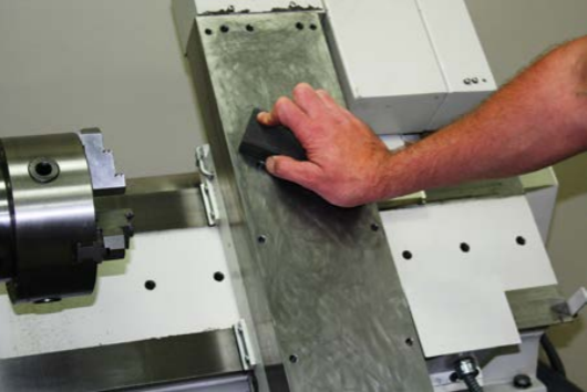
-
Use a machinist stone (or similar) to clean the bottom of the turret.
Install the Turret
WARNING! Transport and Lift Hazard: The transport, lifting, and moving of turret must be done by qualified professionals.
-
Screw the eye bolt tightly into the turret and attach the shackle.
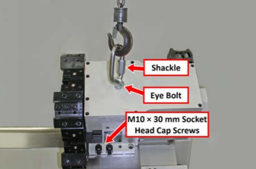
-
Use a lift system to raise the turret above the lathe.
IMPORTANT! Keep the turret attached to the lift system until instructed to remove.
-
Use an 8 mm hex wrench to screw two M10 x 30 mm socket head cap screws two-thirds of the way into the two slots. Do not install the M10 flat washers.
-
Use a lift system to lower the turret onto the two screws installed in the slots.
-
Install the remaining four M10 x 30 mm socket head cap screws and M10 flat washer into open positions on the front and back of the turret.
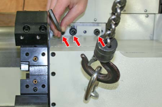
-
One at a time, remove the two M10 x 30 mm socket head cap screws from the slots.
-
Add one M10 flat washer to each screw.
-
Reinstall the M10 x 30 mm socket head cap screws and M10 flat washers to the slots.
-
Snug down all six screws tightly.
-
When the turret is completely secure, disconnect the lift system from the turret’s eye bolt.
-
Remove the eye bolt.
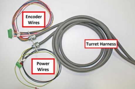
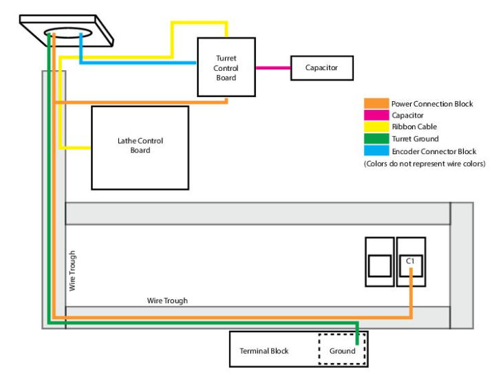
Route Wires to the Electrical Cabinet
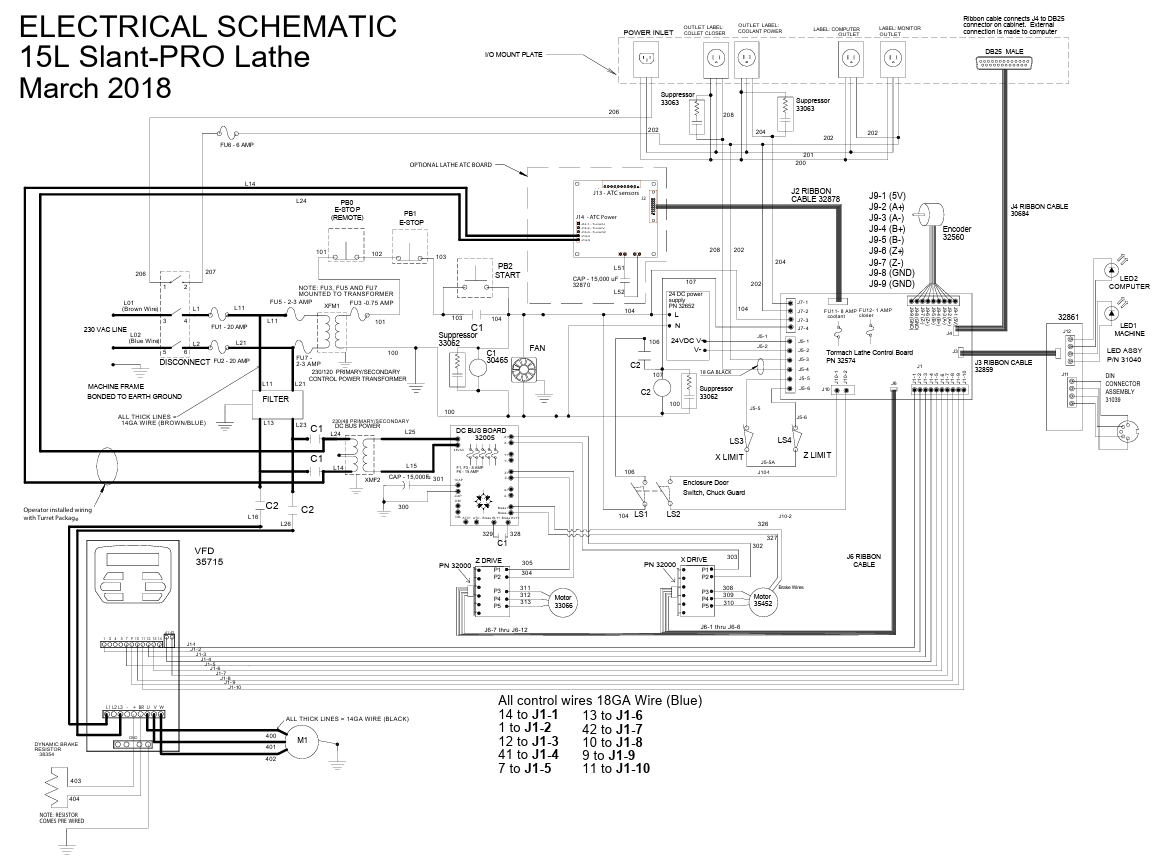
For further details on turret electrical wiring, refer to the following image and/or the electrical schematic in the lathe's operator manual.
-
Power off the machine and the PathPilot controller.
-
Push in the machine's red Emergency Stop button, which removes power to motion control.
-
From the PathPilot interface, select Exit.
-
Turn the Main Disconnect switch to OFF on the side of the electrical cabinet.
-
-
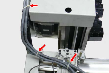
Route the turret harness over the back of the lathe.
-
Use cable ties (included) to secure the turret harness in the locations shown in the following image.
-
Route the turret harness into the lathe casting and out through casting hole on the opposite side of the lathe.
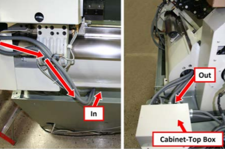
IMPORTANT! Verify that the turret harness is free from entanglement throughout its full motion.
-
Pull the turret harness through the casting far enough so that the new cover plate can reach beyond the cabinet-top box.
-
Open the electrical cabinet door on the side of the lathe.
-
To begin routing the power and encoder ends of the turret harness into the electrical cabinet, you must first unscrew the removable cover plate from the cabinet-top box; set screws aside.
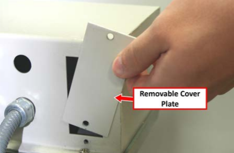
NOTE: If your lathe doesn't have a removable cover plate, we can help. Create a support ticket with Tormach Technical Support at tormach.com/how-to-submit-a-support-ticket for guidance on how to proceed.
-
Carefully feed the power and encoder wires down into the cabinet-top box. Pull the wires into the electrical cabinet far enough so that they can reach all connections.
-
Use the two screws set aside earlier to install the new cover plate and turret harness assembly to the cabinet-top box.
-
Thread four M4 standoffs (PN 50765) into the four pre-drilled and pre-tapped holes on the electrical cabinet back panel.
-
Use four M4 screws (PN 50838) to mount the turret control board to the standoffs that you installed in the previous step.
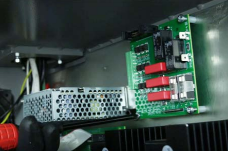
Make Electrical Connections
An illustration of turret wire routing inside the electrical cabinet is shown in the following image. The steps to follow detail the connections shown below.
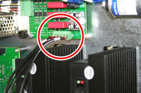
-
Use two M4 x 10 mm pan head screws to mount the capacitor and capacitor bracket on the back panel of the electrical cabinet.
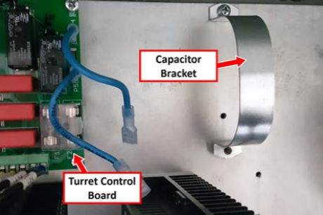
NOTE: If the back panel of your electrical cabinet doesn’t have two holes to mount the capacitor bracket, use the bracket as a template to drill and tap the holes.
-
Locate two loose blue capacitor wires marked L51 and L52.
-
Connect wires L51 and L52 between capacitor terminals and terminals P4/P5 on the turret control board.
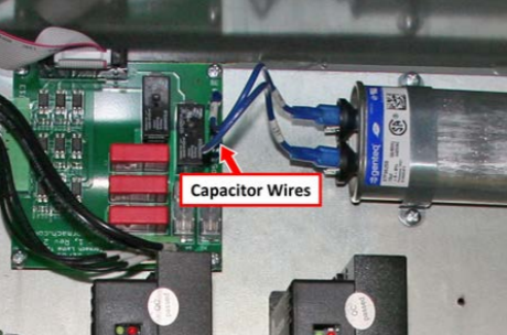
NOTE: The capacitor is non-polar. There is no wrong way to connect.
-
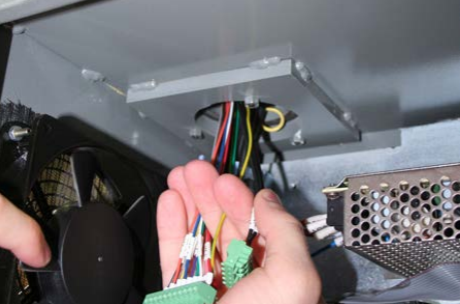
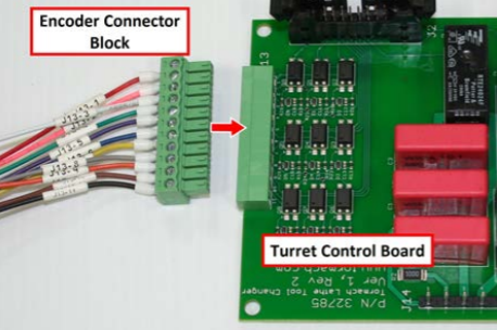
Locate and identify three end wire configurations on the turret harness. Make sure that the cncoder connector block wires are in sequential order.
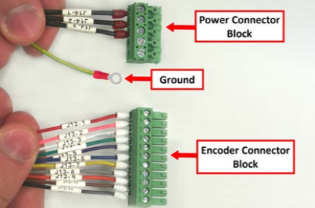
-
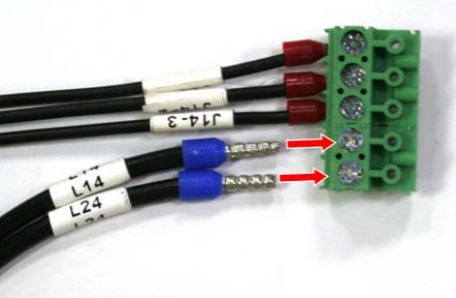
Locate two loose turret power wires marked L14 and L24. Loosen the lock screws on the power connector block, and connect wires L14 and L24. Re-tighten screws snugly.
-
Remove the necessary wire trough covers from the electrical cabinet, and toute the power and ground wires through them.
-
Route the power connector block to the turret control board, and then plug it in.
IMPORTANT! To avoid damage to the turret control board pins, carefully align the power connector block.
-
Route the loose ends of the power connection block (wires L14 and L24) through the wire troughs and to the C1 contactor.
-
Loosen the terminal lock screw above wire L14 on the C1 contactor, and then piggyback the L14 spade terminal onto the existing L14 connection. Re-tighten the terminal lock screw above wire L14 to secure both terminal wires.
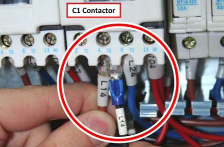
-
Loosen the terminal lock screw above wire L24 on the C1 contactor, and then piggyback the L24 spade terminal onto the existing L24 connection. Re-tighten the terminal lock screw above wire L24 to secure both terminal wires.
-
Route the loose end of the turret ground wire through the wire troughs and to the green-colored section of terminal block.
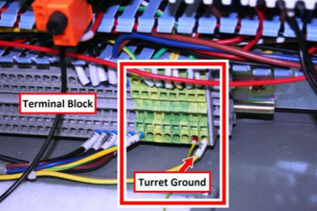
-
Cut the eyelet off of the turret ground wire, and then twist the wire ends together.
-
You can connect the turret ground wire into any available slot in the green-colored section of the terminal block. To make the connection:
-
Slowly insert the end of a small, flat-head screwdriver straight into the slot above or below the wire.
-
Pry the terminal clip open carefully.
-
Insert the wire into the terminal block, and then slowly remove the screwdriver.
-
NOTE: If the turret ground wire does not reach the terminal block, attach the provided turret ground extension.
-
Route the encoder connector block to the turret control board, and then plug it in.
-
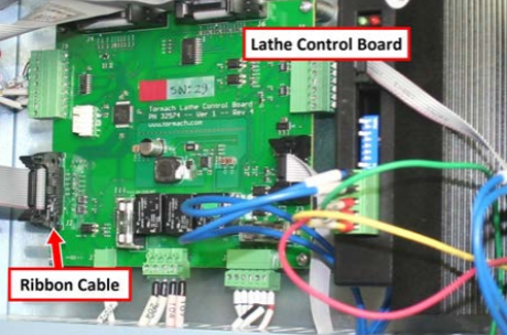
Connect one end of the ribbon cable to the turret control board.
-
Route the opposite end of the ribbon cable through the wire trough and connect it to the lathe control board.
-
Use two mounting tabs, M4 × 10 mm pan head screws, and cable ties to secure excess encoder connector block and ribbon cable connections to the back of the electrical cabinet.
NOTE: Holes are pre-drilled and tapped.
-
Reinstall the wire trough covers.
IMPORTANT! You have completed installing the turret on the lathe. You must now follow the instructions to align the turret. Make sure the lathe enclosure is installed before attempting any alignment procedures. For information on enclosure installation, refer to documentation for that product.
Alignment
IMPORTANT! Before attempting the following procedures, become familiar with the lathe control system (in the lathe operator's manual). This will make alignment quicker and minimize the possibility of machine damage.
Tools Required
-
Magnetic-base dial indicator with fine adjustment
-
Micrometer
-
8 mm hex wrench
-
Assorted precision shims
-
Rubber mallet
-
Clean rag
Adjust X-Axis Alignment
-
Power on the machine and the PathPilot controller.
-
Turn the Main Disconnect switch to ON on the side of the electrical cabinet.
-
Twist out the machine's red Emergency Stop button, which enables movement to the machine axes and the spindle.
-
Press the Start button.
-
Bring the machine out of reset and reference it.
-
-
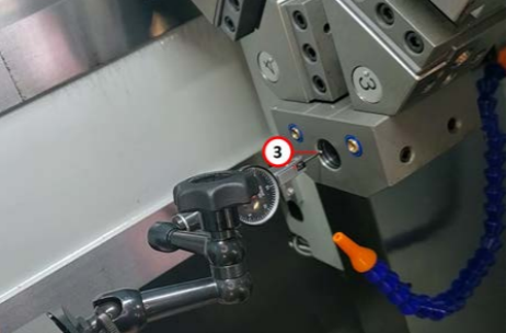
Rotate the turret so that pocket number 3 or pocket number 7 is presented to the spindle.
NOTE: You can use either pocket — both have boring bar holders and are opposing one another, which makes them ideal for alignment.
-
Mount the dial indicator's magnetic base on the spindle. Position the indicator so that, when you rotate the spindle by hand, the indicator sweeps a bore approximately the size of the boring bar holder.
-
Jog the turret close to the indicator and turn the spindle by hand. Adjust the position of the indicator until it's sweeping the inside diameter of the boring bar holder.
-
Set the indicator reading to zero at the initial contact point.
-
Sweep the bore with the indicator:
-
Ensure the reading is the same on both sides of the bore along the machine's X-axis.
-
Jog the machine in X in step mode (0.001 in. increments) until equal readings are achieved.
NOTE: At this step, the reading itself on the dial isn't important — just that the reading is the same in both positions.
-
If needed, fine-adjust the indicator diameter to maintain an accurate sweep.
-
Once the readings match, note any discrepancy in the third position. This value determines the difference in alignment of the Y-axis, which you can resolve by shimming the turret.
-
Determine the shim thickness needed:
-
Because you're using a bore for alignment, the difference in the indicator readings is twice the required turret adjustment.
-
Use a shim that is half of the indicator reading discrepancy from Step 7 (for example, for a reading of 0.003 in., use a 0.0015 in. shim).
Adjust Y-Axis Alignment (Shim Installation)
-
Before installing the shims, make sure that you can easily return to the current position of the turret:
-
From the PathPilot interface, in the X (Dia) DRO field, type 0. Then select the Enter key.
-
While you're installing the shims, be careful to not disturb the indicator.
-
We recommend backing the Z-axis away from the indicator before installing the shims.
-
Loosen the turret bolts (three on top, three on bottom) with an 8 mm hex wrench, but do not remove them.
-
Verify that the shim is clean and free of debris, and then insert the shim under the front of the turret. Make sure that the shim doesn't bend while you're installing it.
-
Carefully tighten the outside and inside bolts on the front and rear of the turret. You can keep the middle bolt loose while you recheck the alignment.
-
Recheck the X and Y readings. If readings are still off, adjust the shim thickness and repeat the process.
-
Change to pocket number 7 and repeat X and Y alignment checks.
-
Ensure both pockets show consistent readings.
-
If necessary, adjust to balance the difference between both holders.
Verify Radial Alignment
-
Change to tool number 6.
-
Remove the wedge block from tool number 6, and clean off the face of the turret if necessary.
-
Mount the indicator on the Z-axis rail, and position the needle so that it's as parallel to the Z-axis as possible.
-
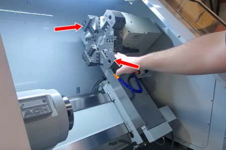
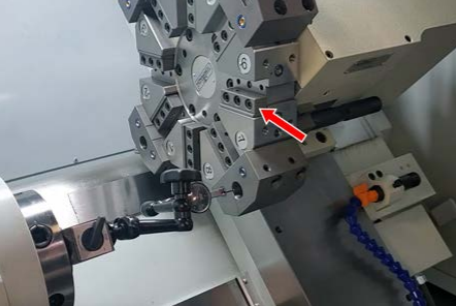
Sweep the face from tool number 6 to tool number 2 with the indicator as shown in the following image.
-
Note any discrepancy between the faces. This value determines the shim thickness needed. Minor deviations within 0.0005 in. are acceptable.
-
Loosen the turret bolts, insert the shim at the rear of the turret, and re-tighten the bolts.
-
Recheck alignment and make final minor adjustments as needed.
-
Re-install the wedge block in tool number 6.
Verify Turret Face Parallelism
-
Mount the indicator on the Z-axis rail, and position the needle so that it's as parallel to the Z-axis as possible.
-
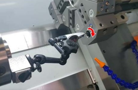
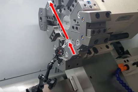
Sweep the face of the turret with the indicator as shown in the following image. Make sure that you don't sweep over any features that are proud of the surface (like the coolant ports).
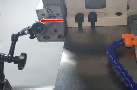
-
Note any movement in the dial indicator. Minor deviations within 0.0005 in. are acceptable.
-
If adjustment is needed:
-
Loosen turret bolts slightly.
-
Use a rubber mallet to tap the turret into alignment.
-
Re-tighten bolts and recheck alignment.
-
-
Verify that all of the turret bolts are re-tightened.
Finalize the Installation
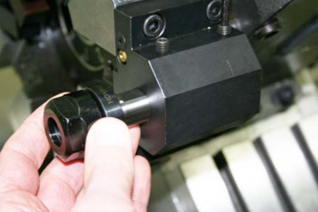
Coolant Fitting
-
Locate the pre-installed coolant fitting on the turret.
-
Screw on the lathe’s coolant hose.
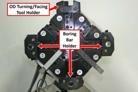
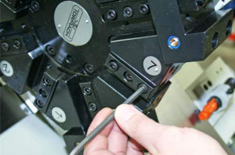
Boring Bar Holder Use
IMPORTANT! Mark the factory-installed location of each boring bar holder on the turret with a paint pen for future re-install (if removed).
Two types of tool holders are pre-installed on the turret. If removal or relocation is necessary, unscrew four bolts on each.
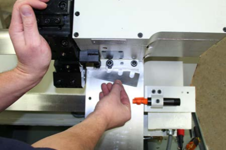
To insert a tool in any boring bar holder:
-
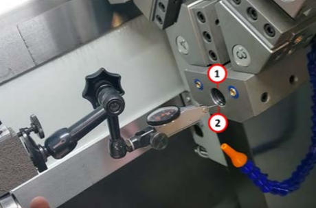
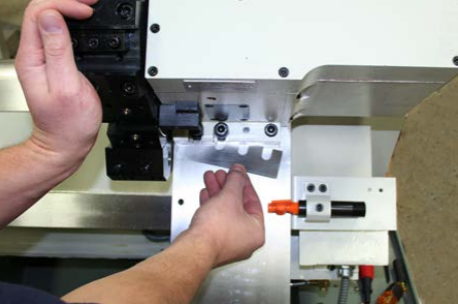
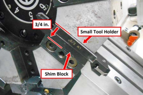
Identify the tool pocket to be used and insert a 3/4” tool.
-
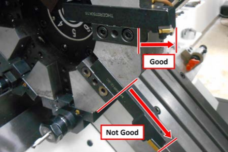
Make sure that the tool is flat as shown in the following image. Tighten snugly. To remove a tool, reverse this process.
NOTE: If using a smaller-sized tool, use appropriate-sized bushing.
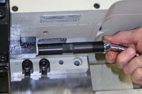
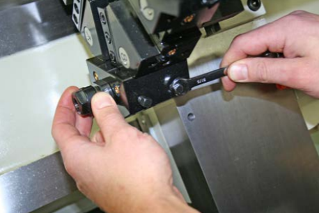
Wedge Block/Tool Extraction
-
Loosen two outside screws in the wedge block; remove the extraction bolt in the center hole and keep for later use.
-
When the tool is inserted, push the wedge back to seat in the rear of the pocket.
-
Tighten the wedge block snugly.
-
To extract the tool, loosen two wedge block screws, insert the extraction bolt into the center hole and — while holding the tool with one hand — screw in the extraction bolt until the tool comes free.
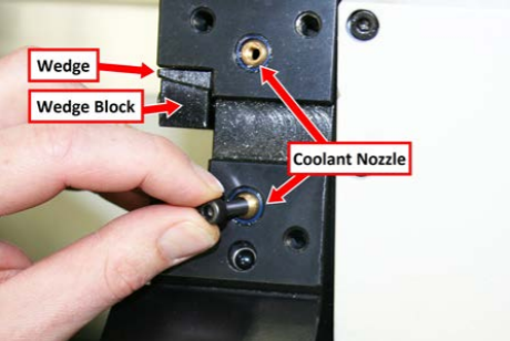
Coolant Nozzle
Use M5 × 8 mm socket head cap screw (or hex wrench) to aim the coolant nozzle as needed. Make sure that the nozzle allows coolant to flow to the cutting edge of the tool.
Setup
Tool Alignment and Crash Avoidance
Tool alignment pertains to how the cutting edge of the cutting insert is oriented/positioned along the X, Y (tool height), and Z axes. While turret alignment with the axes was addressed earlier in this document, some cutting tools may require additional alignment. A lathe turret allows the mounting of multiple tools for fast, accurate, mid-program tool changes. That said, it’s important to note that when using a CNC lathe there is always the risk of tool crashes – into the work, the spindle head stock, or the chuck. This applies to CNC lathes equipped with turrets as well as gang-mounted tools. Therefore, careful tool and program planning are necessary. Do test runs (cutting air) at decreased feed rates. Take every precaution necessary to avoid a tool crash. Choosing which tool is mounted in which turret position is extremely important. Since operator machining setups vary widely, Tormach is unable to instruct where to mount your tools. This following section is intended to give some general pointers on tool mounting.
WARNING! Ejection Hazard: Do not allow turret tools to come in contact with rotating spindle as objects may be ejected from machine with deadly force.
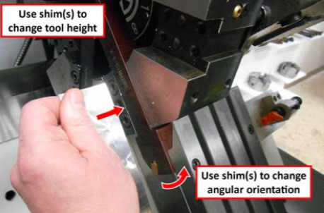
Shimming
Shimming of tools to set tool height and orientation is common in any lathe set up. Shims come in a wide variety of shapes, sizes, materials, and thicknesses. Shims typically range in size from 0.0005 in. to 0.01 in. or larger. Stacking of shims to get the right thickness is not ideal, but not uncommon either.
Nominal Tooling Size
We advise using 3/4 in. tooling for the turret, but it is possible to use smaller tool holders. Keep in mind that these must be shimmed so tool tip is in line with the spindle axis.
Tooling Length
To reduce vibration and deflection, mount tools with the cutting tip as close to the turret clamp or block as possible.
Tool Turret Position Repeatability
While turret operation is fairly accurate and repeatable, it’s impossible to be perfect. During turret installation, height and alignment were adjusted for one pocket. This resulted in all other pockets being close to but not exactly the same pocket height and alignment at the first one. Since most lathe tools aren’t sensitive to this alignment, being off by, for example, 0.003 in. may not have any measurable impact on a part. Some tools, such as parting tools for example, need to be as close to perfect as possible. We recommend mounting tools sensitive to alignment in the first pocket (used for aligning the turret), or shimming (up/down, side to side) appropriately.
There is sometimes a trial and error process that occurs to learn where this may or may not be relevant.
IMPORTANT! Be aware that it is possible for a tool to be mounted out far enough that it could crash into the lathe bed.
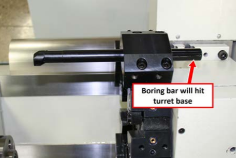
IMPORTANT! Some 3/4 in. boring bars can protrude out too far towards the turret base, resulting in a crash during a tool change. To eliminate this issue, cut the boring bar shorter.
Turret Tool Positions
Be aware of the crash potential of all tool positions during use of each tool.
For example, when using turret position #1 for a short tool like a tap (that requires turret be very close to the workpiece), be aware of tools in the remaining positions (2-8), as the tap is cutting into the stock.
Issues to consider:
-
Is the boring bar or a long drill bit (in position #2) going to hit the chuck or head stock? This is a complicated crash scenario to predict. Simply creating a CAM program, inserting the code in the lathe, loading tools, and pushing Cycle Start – without considering where all tools are at all times – can trigger such a crash scenario.
-
Typically the greatest concern is related to tools oriented parallel to the spindle. For example, if there are large variations in length of tools mounted in boring bar holders, mount the tools as far away from each other as possible.
Troubleshooting
Lock Switch Adjustment
The turret has a tool lock switch that may require adjustment to achieve a complete locking of the turret face after a tool change. To adjust:
-
Push the Emergency Stop button.
-
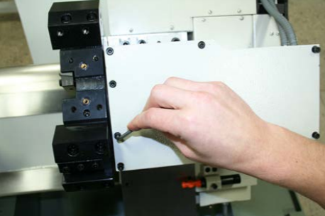
Remove eight socket head cap screws to remove the motor cover from turret.
-
Pull on the motor belt in a clockwise direction to rotate turret motor until turret is in a fully-locked position.
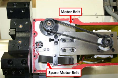
NOTE: A spare motor belt is located under the motor cover.
-
Check to make sure that the turret is locked by inserting a 3/4 in. broom handle (or similar wooden dowel) into the pocket and then rotating the turret back and forth. The turret is mechanically locked when no further rotation is possible.
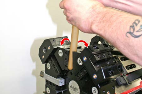
IMPORTANT! Only use a wooden material for this test. Other materials may damage the turret.
-
On the operator panel, twist out the Emergency Stop button, and then push the Start button.
-
Use a flat-head screwdriver to loosen two screws on the lock switch bracket.
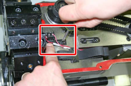
-
Move the bracket left and, using a multimeter, touch contact and a ground; adjust switch location until the multimeter reads 0 volts.
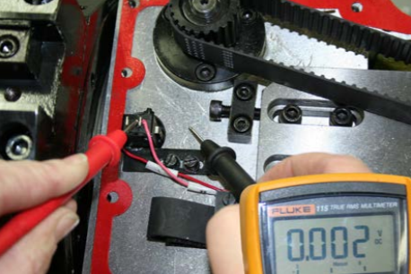
NOTE: Ensure that your multimeter lead is placed on the pink wire as shown. The position of the wire on the switch may differ from the pictured position.
-
Move the bracket right until multimeter reads 24 volts.
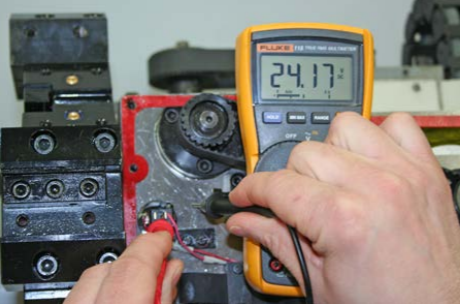
-
Re-tighten the bracket and re-install the motor cover.
Relocate the Oil Line
IMPORTANT! The procedure to relocate the oil line is only required for machines serial number 10192 and below.
You must relocate the lathe’s carriage oil line to allow for turret clearance.
-
At back of the lathe, disconnect the oil line from the oil manifold.
-
Use a Phillips screwdriver to remove the oil line bracket and set it aside.
-
Put the disconnected oil line back through the carriage.
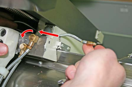
-
Reconnect the oil line to the manifold.
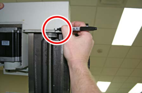
-
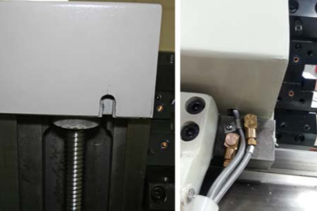
Locate the notch below the X-axis motor cover, and mark the cutout location.
-
Use a Phillips screwdriver to remove four screws on the X-axis motor cover, and then remove the motor cover. Set all aside.
-
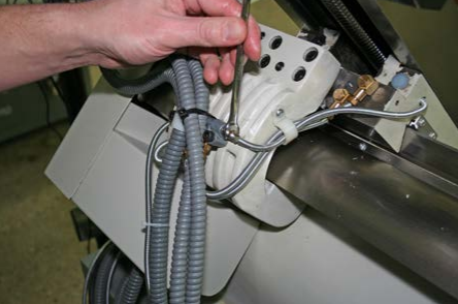
Slowly move the X-axis down, making sure to not pinch the oil line.
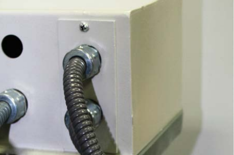
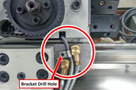
-
Attach the oil line bracket (set aside earlier) to the oil line and position as shown in the following image. Make sure that the tension in the oil line is correct. Then, mark a drill hole for the bracket.
-
Use a #19 drill, M5 × 0.8 tap, and a tapping handle to drill and tap the marked location.
-
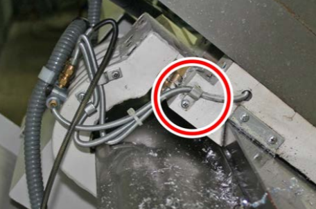
Mark a cutout slot — 5/8 in. × 1/2 in. — on the X-axis motor cover as shown in the following image. Use a 1/2 in. drill bit to drill a hole
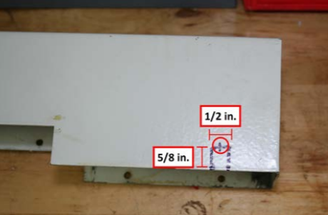
-
Use a hacksaw to cutout the remainder of the slot.
-
Reinstall the X-axis motor cover. Make sure that the oil line has clearance around the slot.
To view a PDF version of your manual, go to Tormach document TD10413.
If you have additional questions, we can help. Create a support ticket with Tormach Technical Support at tormach.com/how-to-submit-a-support-ticket for guidance on how to proceed.