![]()
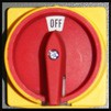
Power Off/Power On Procedure
IMPORTANT! Do not power on motors and drives via the green Start button before powering on the controller that oversees their operation. Ensure the controller is on and the PathPilot® interface is loaded before powering on the lathe. Likewise, make sure to depress the red E-stop before powering off the controller using the Exit button in the PathPilot interface.
Power Off/On Procedure
|
Power Off/On Procedure |
||
|
Power Off |
|
|
|
||
|
||
|
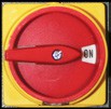
Power On |
|
|
|
||
|
||
|
||
Confirm Spindle Direction
Upon initial lathe setup, confirm the lathe’s spindle is rotating in the correct direction.
![]()
-
Power on the lathe and controller according to the Power Off/On Procedure detailed earlier in this chapter; close the chuck guard.
-
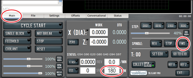
On the Main screen in the PathPilot interface, set chuck speed by entering 180 in the RPM field (see Figure 1). Then, press the Enter key on the keyboard.
-
Click Spindle FWD to start spindle rotation (see Figure 1).
-
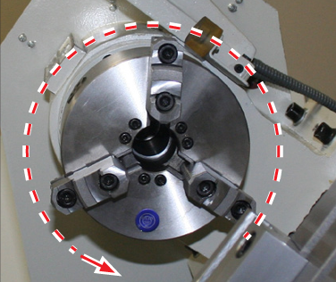
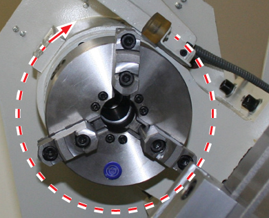
Observe spindle direction to confirm forward is correct (see Figure 2).
-
Repeat to confirm reverse is correct by clicking Spindle REV and observing spindle direction (see Figure 3). If not rotating as shown, refer to Spindle Direction is Reverse.
Lathe Axes Definition
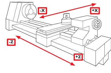
The lathe has two axes of motion, denoted as the X-axis and the Z-axis. The Z-axis is parallel to rotational axis of the spindle. The X-axis is perpendicular to the Z-axis and nominally parallel to the long dimension of the carriage (see Figure 4). The –X direction is toward the front and +X direction is toward the rear. The –Z direction is toward the headstock and the +Z direction is opposite the headstock.
Workholding
![]()
The 15L Slant-PRO comes with a D1-4 spindle that includes a 5C taper insert for precision turning of stock less than 1.125” in diameter. Because this spindle has both D1-4 mounting and a 5C insert, you may configure lathe for use with either 6” D1-4 chuck or a 5C collet closer. A different motor pulley is included for use with the 5C configuration that allows you to run the lathe with a higher maximum spindle RPM when using 5C. For example, 3500 RPM for the 5C configuration and 2500 RPM with the 6” chuck configuration.
5C Collet Configuration (Maximum Speed Rating: 3500 RPM)
An optional lever-action 5C Collet Closer (PN 33283) must be purchased to use a 5C collet with a lathe. This lever-style closer can be refitted with an air cylinder for automatic control of closer operation via M-code. For more information and setup and adjustment procedures, refer to documentation that ships with the product.
D1-4 Chuck Configuration (Maximum Speed Rating: 2500 RPM)
For larger work pieces, 3-jaw 6” Chucks (PN 33156) and 4-jaw 6” Chucks (PN 33336) are available that fit the D1-4 cam lock spindle nose. Because larger work pieces require lower spindle RPMs and higher torque, the 6” chuck accessories necessitate the use of a smaller motor pulley. This pulley must be installed along with the chuck. This reduces the maximum spindle speed from 3500 RPMs to 2500 RPMs, but greatly increases the low-speed torque available for turning at lower RPMs.
Tooling
The three tooling styles available for the Tormach 15L Slant-PRO are detailed below. All three options may be mixed – for example, a gang plate mounted tool could be used in conjunction with tooling mounted in a turret.
Quick Change Tool Post (QCTP)
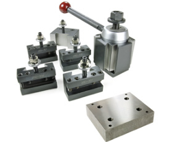
A manual Quick Change Tool Post Kit (PN 33272) can be mounted to the carriage to allow fast, repeatable manual tool changes (see Figure 5). The QCTP uses a dovetail and tapered gib to hold tool holders to the post at adjustable, repeatable distances from the lathe bed so that individual tools can be brought up to centerline height of the spindle. Available QCTP tool holders include standard 3/4” OD, ID (boring), and parting tool holders.
8-position Turret
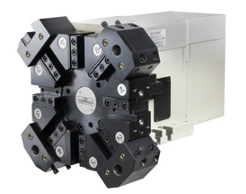
The 8-position Turret (PN 33273) allows automatic tool changing of both turning and boring tools as well as through- turret flood coolant. When equipped with a turret (see Figure 6), the lathe automatically changes tools, numbers 1-8. Gang tooling or quick change tooling may be used in conjunction with a turret on lower portion of carriage.
Gang Tooling
A gang tooling plate with three T-slots and a riser block can be mounted to the carriage to facilitate mounting tool holders in industry-standard, gang-tool holding blocks (see Figure 7). Risers are available for both 1/2” and 3/4” centerline heights.
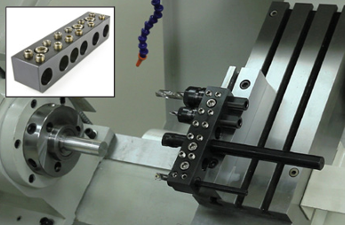
This option offers higher precision and faster tool change times than a manual tool post or turret, but requires vigilance to ensure appropriate clearance between tool, workpiece, and chuck/spindle nose. Gang setups are ideal for small diameter, short parts. Additionally, gang blocks can be swapped out as a single unit, dramatically reducing part setup time.
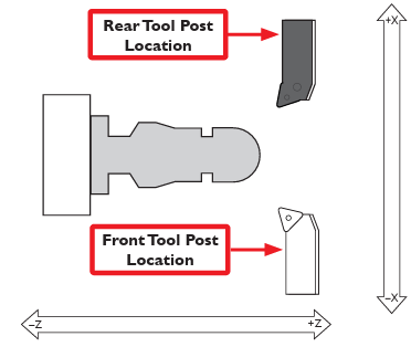
Front Tool Post and Rear Tool Post Locations
Tools are mounted on the carriage in either a front tool post or rear tool post position. Front tool post tools address the workpiece by moving in +X direction (see Figure 8).
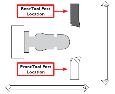
Rear tool post tools address the workpiece by moving in –X direction (Figure 9).
The three tooling configurations for the 15L Slant-PRO have different tool post locations, detailed in the following table:
|
Tooling Configuration |
Tool Post Locations |
|
Quick change tool post |
Front tool post |
|
Gang tooling |
Front or rear tool post |
|
Turret |
Rear tool post |
Right-handed and Left-handed Tools
Tools have either a right-handed or left-handed orientation; right- or left-handed tools can be mounted on the carriage in either the front tool post or rear tool post position (see Figure 8 and Figure 9). The tool can be mounted either with the cutter facing toward the operator or turned with the cutter facing away from the operator, as shown in Figure 8 and Figure 9. Four cutting configurations are available for both a right- and left-handed tool (see Figure 8 and Figure 9).
Right- and left-handed tools cut in different directions depending on the spindle rotation direction, detailed in the following table:
|
Tool |
Spindle Direction |
Cutting Direction |
|
Right-handed |
Forward |
–Z |
|
Reverse |
+Z |
|
|
Left-handed |
Forward |
+Z |
|
Reverse |
–Z |
Right-handed tools are commonly used for general purpose turning. Left-handed tools are sometimes used for back chamfering or grooving.
Looking for more information?
This is a section of the 15L operator's manual. To view the whole manual, go to Tormach document UM10225.
If you have additional questions, we can help. Create a support ticket with Tormach Technical Support at tormach.com/how-to-submit-a-support-ticket for guidance on how to proceed.