Tools and Items Required
-
500-lb capacity engine hoist
-
Lifting straps
-
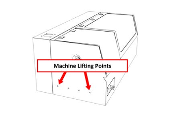
Find the four M10 lifting eyelets provided in the tool box. You'll use them as lifting points to move the machine off of the pallet.
-
Install the two M10 lifting eyelets into each end of the machine by hand in the locations shown in the following image. Verify that the lifting eyelets are installed hand tight.
WARNING! Transportation and Lift Hazard: Before moving the machine, you must confirm that all persons are clear of the area below the machine. Qualified professionals must transport, lift, and move the machine. Moving parts can entangle, pinch, or cut you, causing death or serious injury.
-
Using lifting straps (not provided) on a 500-lb capacity engine hoist, lift the machine up from the pallet.
-
Depending on where you're installing the machine, do one of the following:
-
Tormach Machine Stand Go to "Secure the Machine to the Stand".
-
500-lb Capacity Workbench Go to "Secure the Machine to a Workbench".
Secure the Machine to the Stand
-
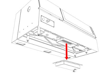
Remove the drip tray from the bottom of the machine.
-
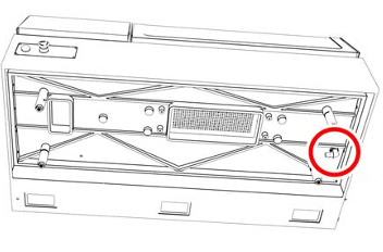
Identify the two fixed-length standoffs on the bottom of the machine, and verify that they're tight.
-
Measure the length of the two fixed standoffs. Then, adjust the two adjustable standoffs until they're the same length as the fixed standoffs.
-
Tighten the jam nuts on the two adjustable standoffs with a 19 mm wrench.
-
Identify the four M14 set screws included in the hardware box from the stand.
-
Thread one of the set screws into each of the standoffs on the bottom of the machine. Then, tighten them using a hex key.
-
Identify the coolant tube in the chip basket. Then, attach the coolant tube onto the fitting on the bottom of the machine.
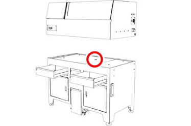
NOTICE! You must route the coolant tube through the provided hole in the stand, as described in the following step. If you don't route the tube through the stand, it may result in coolant leaks.
-
Carefully lower the machine onto the machine stand while routing the coolant tube through the hole in the middle of the stand.
-
Remove the four M10 lifting eyelets from the sides of the machine.
-
Completely open each drawer on the stand. Then, identify the plastic tabs on the drawer slides. Push the tabs up or down to remove the drawer from the drawer slide.
NOTE: One tab gets pushed up, and the other pushed down.
-
Install the nuts onto the bolts that secure the machine to the stand.
-
Use an adjustable wrench to slowly lower the machine by adjusting the feet into the legs. Work your way around the machine, adjusting each foot a little at a time, being careful not to put the machine out of balance. Continue until the threaded rod on the feet is mostly inside the leg, the machine is stable, and the coolant drawer still fits under the stand.
Secure the Machine to a Workbench
-
Remove the risers from the base of the machine.
-
Install the machine feet in place of the risers that you removed in Step 1.
-
If you're adding flood coolant to your system, attach the coolant tube onto the fitting on the bottom of the machine.

-
Carefully lower the machine onto the 500-lb capacity workbench.
-
Remove the four M10 lifting eyelets from the sides of the machine.
-
Check the machine to make sure it doesn't rock back and forth.
-
If it moves, you must level the machine on the workbench. Go to Step 7.
-
If it doesn't move, you've completed the steps to secure the machine to the workbench.
-
Identify the access panels on each end of the machine enclosure. Remove the button head cap screws with a 3 mm hex key. Then, set aside the screws and the access cover.
-
Loosen the jam buts on the leveling feet with a 19 mm wrench.
-
Use a wrench to thread the machine feet in or out to level the machine on the work bench.
-
Tighten the jam nuts on the leveling feet with a 19 mm wrench.
-
Use a 3 mm hex key to re-install the screws and access cover that you set aside earlier.
NOTE: When using the lathe with a desktop coolant system, it's important to periodically inspect the inside of the drip tray for accumulation of chips or other debris. This helps to prevent clogs of the drain line, which can result in coolant backing up into the machine's enclosure.
Looking for more information?
This is a section of the 8L operator's manual. To view the whole manual, go to Tormach document UM10753.
If you have additional questions, we can help. Create a support ticket with Tormach Technical Support at tormach.com/how-to-submit-a-support-ticket for guidance on how to proceed.