To properly validate the core installation of your machine, you must understand how to power on and off the machine and use the controls.
Complete the following steps in the order listed:
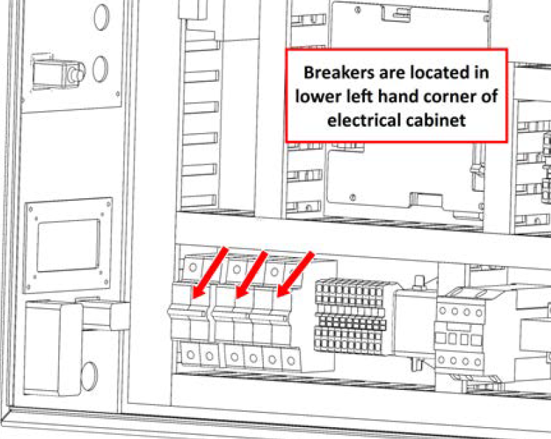
Check Machine Breakers
Check that all breakers in the electrical cabinet are switched on (up position).
Power on the Machine
Use a multimeter to verify that the electrical service in your location meets the following requirements. If your location does not meet these requirements, do not install the machine. Instead, you must consult with a local electrician about your options.
-
Primary Power Required Single-Phase 230 Vac, 50/60 Hz
-
Recommended Circuit Amperage Dedicated 15 A breaker
-
Connect the machine's mains power cable to the verified electrical service.
-
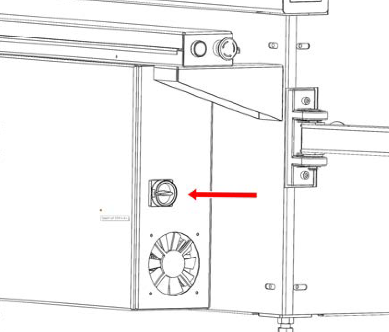
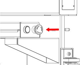
Find the Main Disconnect switch, and then remove the hang tag.
-
Turn the Main Disconnect switch to ON.
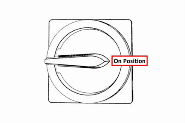
Mains power is now connected to the machine.
-
Push the Power button on the PathPilot controller, if it's not already powered on.
-
Follow the on-screen instructions to configure the PathPilot operating system and PathPilot controller.
When configuration is complete, the PathPilot operating system launches.
NOTE: After you first configure PathPilot, the operating system automatically launches whenever it's powered on.
-
Depending on which monitor you have, do one of the following:
-
Standard Monitor Go to the next step.
-
Touch Screen Monitor You must first make sure that the monitor is configured and calibrated. From the PathPilot interface, in the MDI Line DRO field, type Admin Touchscreen. Then, select the Enter key, and follow the on-screen instructions.
-
-
Rotate the Emergency Stop button one-quarter turn clockwise to release it.
-
Push the blue Reset button to enable the machine.
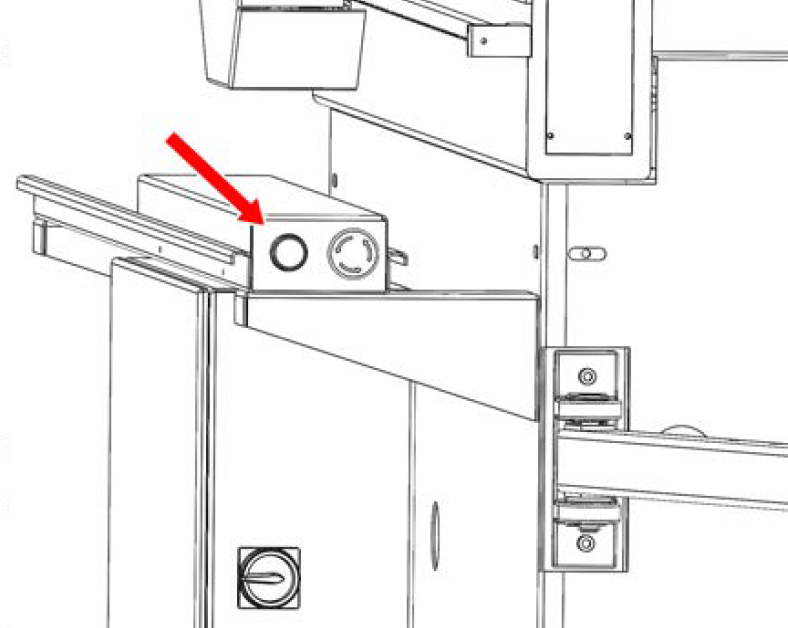
The axis drives are now powered on.
-
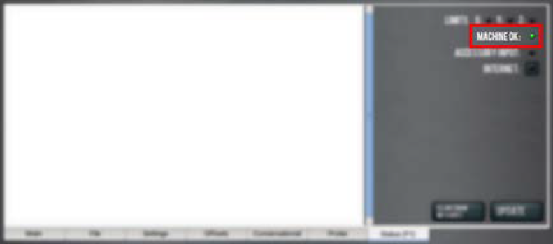
Verify that the blue Reset LED comes on. From the PathPilot interface, on the Status tab, verify that the Machine OK light changes from yellow to green.
Once both are on, the machine is powered on and ready to operate.
-
Select Reset.
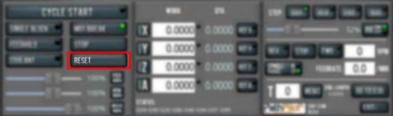
This initializes the connection between the machine and controller.
Verify Axes Function
You must confirm that the axes correctly operate.
-
Reference the axes: from the PathPilot interface, select Ref Z, Ref X and Ref Y.
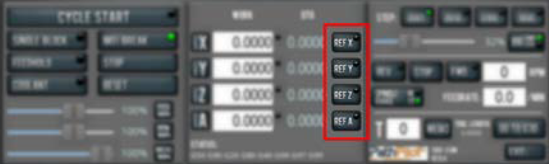
The machine moves to the reference position.
-
Use the keyboard to verify axes motion:
-
Select the Right Arrow key and then the Left Arrow key.
The torch carriage moves right (X+), then left (X-). -
Select the Up Arrow key and then the Down Arrow key.
The gantry moves toward the back end of the table (Y+), then toward the front (Y-). -
Select the Page Down key and then the Page Up key.
The torch lifter moves down (Z-), then up (Z+).
-
If applicable, verify the optional Jog Shuttle:
-
Press any axis button on the Jog Shuttle — X, Y, Z, or A — to select an axis.
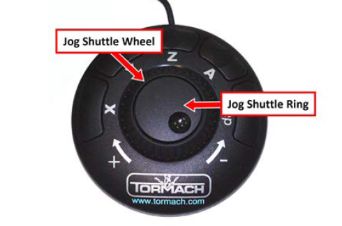
From the PathPilot interface, on the Main tab, the corresponding green Axis light comes on.
-
Turn the Jog Shuttle Ring in any direction to move the selected axis, then turn it in the opposite direction to reverse the direction.
Check Belt Tension
Since brand new drive belts have a tendency to stretch slightly after first use, your Y-axis drive belts might need re-tensioning.
If you notice that the Y axis gantry seems to have excessive backlash or that the servo is struggling to hold a consistent position, follow the maintenance procedure for "Adjust Belt Tension".
If Y-axis gantry movement seems normal and there is no noticeable backlash belt tension adjustment can be deferred until the time defined in the "Maintenance Schedules".
Testing Plasma Source Control
-
Using the "Connectors Reference" verify that the Hyperthem control cable is connected to the correct spot on the rear of your electrical cabinet.
-
Jog the torch to a location several inches above the water table so that you can safely test the arc.
-
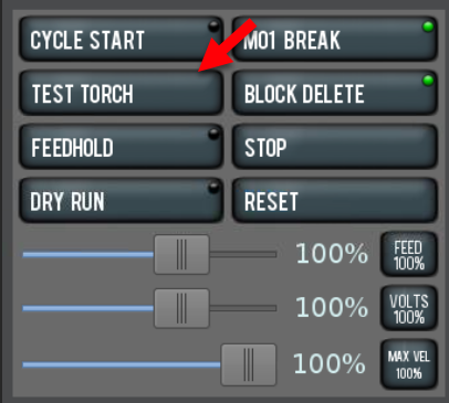
Activate the plasma source and create a pilot arc by pressing the TEST TORCH button in PathPilot.
-
Verify that your plasma source activates and creates a pilot arc (you may have to press the button twice to bypass the "warning puff" function on some plasma sources).
-
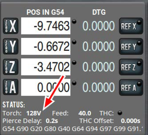
While the pilot arc is active, watch the "Torch Voltage" readout at the bottom of your control screen.
-
You should see an open-circuit voltage of above 100V. If you do not see a voltage reading, follow the "Voltage Feedback" section of the Troubleshooting guide.
Testing Ohmic Probing
-
Make sure that the ohmic probing spade connector is connected to your torch cap.
NOTE: You must be using shielded consumables where the torch cap extends below the nozzle. If the nozzle contacts the workpiece before the torch cap, ohmic probing will not work.
-
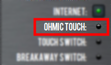
Switch to the Status tab on your PathPilot controller and locate the OHMIC TOUCH led. It should be off initially.
-
Touch the ground clamp lead from the plasma source to the torch cap. You should see the LED switch to green.
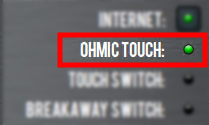
If you your ohmic probe input is not responding the way described above, check the "Ohmic Probing" Troubleshooting section.
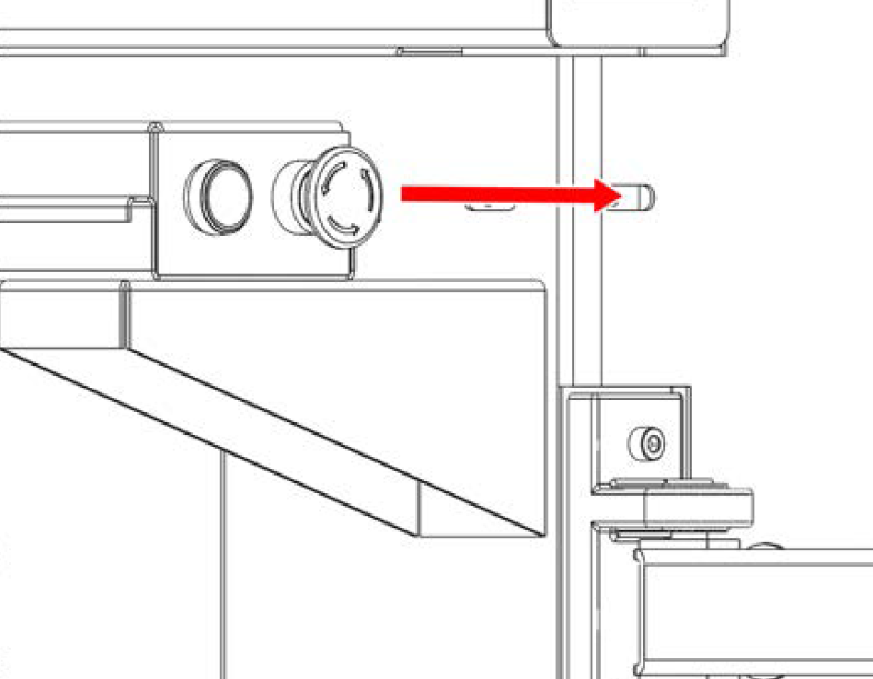
Testing Torch Breakaway
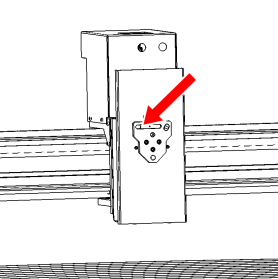
Your Tormach 1300PL is equipped with torch breakaway detection to stop motion in the event that a tip-up during cutting causes a collision with the torch. A proximity sensor is located in the touch mounting base to detect when the mounting clamp has been knocked off.
-
Make sure that the machine is on and PathPilot is running.
-
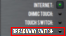
Switch to the Status tab on your PathPilot controller and locate the BREAKAWAY SWITCH led. It should be off initially.
-
Pull the torch clamp away from the base. You should see the LED light up when the torch clamp is removed and extinguish when it is replaced.
Power off the Machine
-
Push the Emergency Stop button to lock it into the disabled position.
With the Emergency Stop button in the disabled position all motion function stops, the Reset button is disabled , and the blue Reset LED goes off. From the PathPilot interface, on the Status tab, the Machine OK light illuminates yellow.
-
From the PathPilot interface, select Exit.
-
When prompted, select OK.
-
Once the PathPilot interface indicates that it's safe to power off the machine, turn the Main Disconnect switch to OFF.
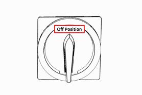
Mains power is disconnected from the machine.
Looking for more information?
This is a section of the 1300PL operator's manual. To view the whole manual, go to Tormach document UM10720.
If you have additional questions, we can help. Create a support ticket with Tormach Technical Support at tormach.com/how-to-submit-a-support-ticket for guidance on how to proceed.