In This Section, You'll Learn:
How to use PathPilot, depending on the activity that you want to do.
Create and Load G-Code Files
To get started with PathPilot, you must first load or create a G-code file.
Load G-Code
To run a G-code program on a PathPilot controller, you must first verify that the file is on the controller. For more information on transferring and moving files, see "Transfer Files to and From the Controller".
To load G-code:
-
From the File tab, in the Controller Files window, select the desired .nc file.
-
Select Load G-Code.
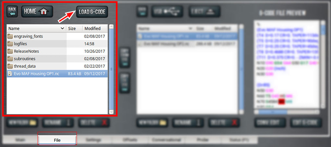
NOTE: This function is only available for files stored on the PathPilot controller.
PathPilot loads the G-code file and opens the Main tab.
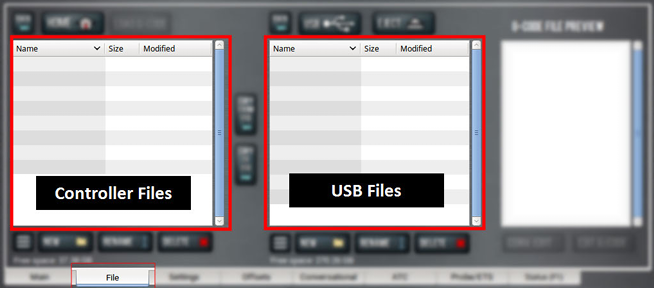
Transfer Files to and From the Controller
To run a G-code program, you must transfer the files to the PathPilot controller. You can either use a USB drive or PathPilot HUB (our cloud-based simulator) to transfer files. For more information on PathPilot HUB, go to hub.pathpilot.com.
To transfer files to and from the controller:
-
Either insert a USB drive into any open USB port, or sign in to PathPilot HUB.
-
From the File tab, select the file to transfer (either in the USB / HUB Files window or the Controller Files window).
NOTE: Select Back to move backward and either Home or USB to move to the highest level.
-
Select the location to which you want to copy the transferred file.
-
Select either Copy <- or Copy ->.
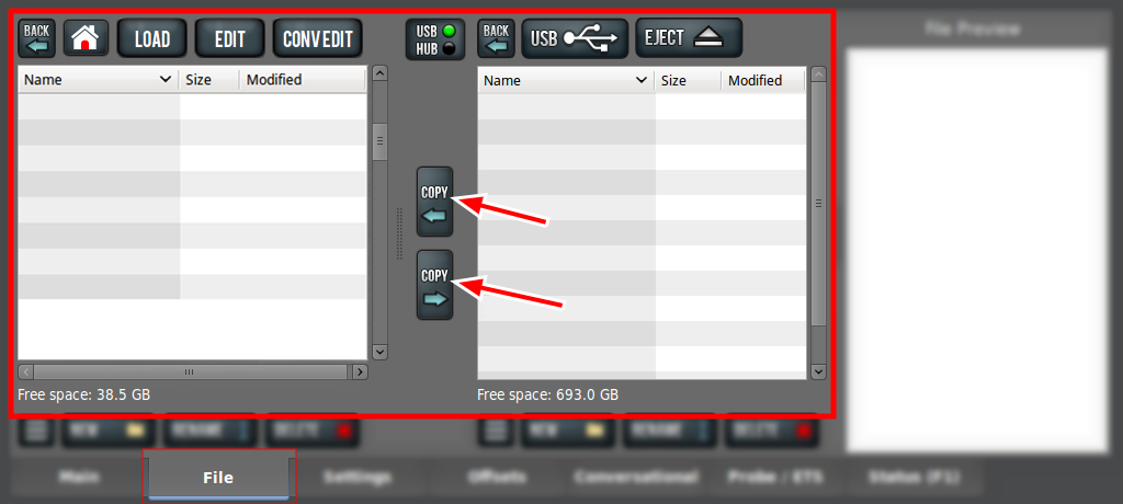
NOTE: The file must have a unique name. If it doesn't, you must either overwrite the file, rename the file, or cancel the file transfer.
-
Select Eject.
It's safe to remove the USB drive from the controller.
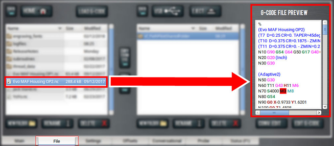
Preview G-Code Files
You can preview an .nc file that's either on the PathPilot controller or on a USB drive.
To preview G-code files:
-
From the File tab, in the Controller Files window or the USB Files window, select an .nc file.
The text displays in the Preview window.
Access Recent G-Code Files
You can load a recently loaded G-code file from the Main tab. For information, see "About the G-Code Tab".
To access recent G-code files:
-
From the Main tab, in the G-Code tab, select the Recent Files menu.
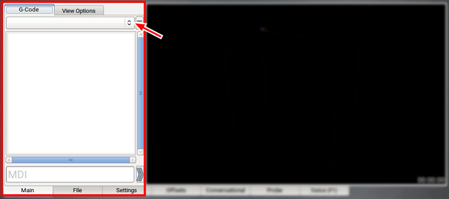
The last five program files loaded into PathPilot display.
-
Select the name of the desired G-code program.
The G-code program loads.
Close the Current Program
-
From the Main tab, on the G-Code tab, select the Recent Files menu.
-
Select Clear Current Program.
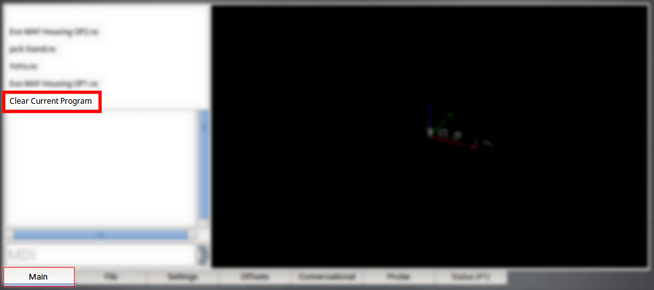
The currently loaded G-code program closes.
Edit G-Code
In PathPilot, there are two ways to edit G-code:
Edit G-Code with a Text Editor
You can edit .nc files that are on the PathPilot controller. If the .nc file is in the USB Files window, you must first transfer it to the controller; go to "Transfer Files to and From the Controller".
To edit G-code with a text editor:
-
From the Controller Files window, highlight the .nc file and select Edit G-code.
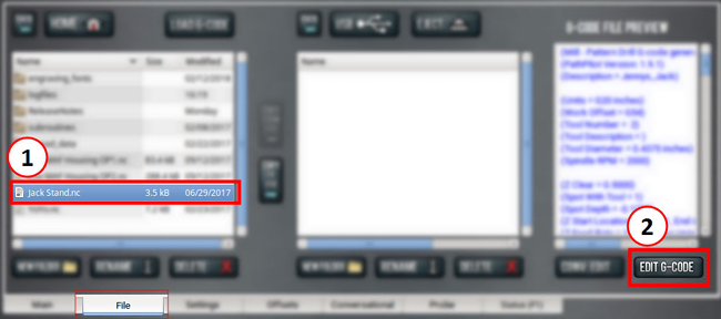
The file opens in a text editor.
-
Make and save the appropriate changes to the file.
-
Close the text editor.
Tip! To quickly edit an already loaded G-code program from the Main tab, you can use a keyboard shortcut: Shift+Alt+E.
Edit G-Code with Conversational Programming
You can edit .nc files that are on the PathPilot controller. If the .nc file is in the USB Files window, you must first transfer it to the controller; go to "Transfer Files to and From the Controller".
To edit G-code with conversational programming:
-
From the File tab, select the .nc file.
-
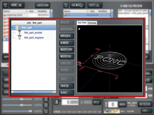
Select Conv. Edit.
The file opens in a job assignment editor window: the program's job assignments are on the left and a preview of the program is on the right.
-
Edit the file contents as needed. Do any of the following:
Change the Step Order
Create a New Job Assignment
Load an Existing G-Code File
Edit a Job Assignment -
Select Save.
The G-code program file is updated.
Change the Step Order
-
Select Move Up, Move Down, Duplicate, or Remove.
Create a New Job Assignment
-
Select Insert Step.
PathPilot opens the Conversational tab. -
Create the new job assignment.
-
Select Insert.
-
(Optional) Edit the job assignment order in the program.
Load an Existing G-Code File
-
Select Insert File. You can insert G-code files that are hand-written, generated from CAM software, or generated from conversational programming in PathPilot.
-
Navigate to and select the .nc file that you want to insert.
-
Select Open.
-
(Optional) Edit the job assignment order in the program.
Edit a Job Assignment
-
Select the job assignment, and then select Conv. Edit.
PathPilot opens the Conversational tab. -
Edit the job assignment.
-
Select Finish Editing.
Tips
-
To restore an edited job assignment to its original parameters: select Revert.
NOTE: Revert is only available for individual job assignments created in conversational programming.
-
To undo all changes made to an entire G-code program: select Close. When prompted, select Close Without Saving.
Read G-Code
Once your G-code file is loaded into PathPilot, you can read it in the following ways:
Expand the G-Code Tab
You can change the size of the G-Code tab if you need more space to view the code. For more information on using the G-Code tab, see "About the G-Code Tab".
To expand the G-Code tab:
-
Select the Window Expander.
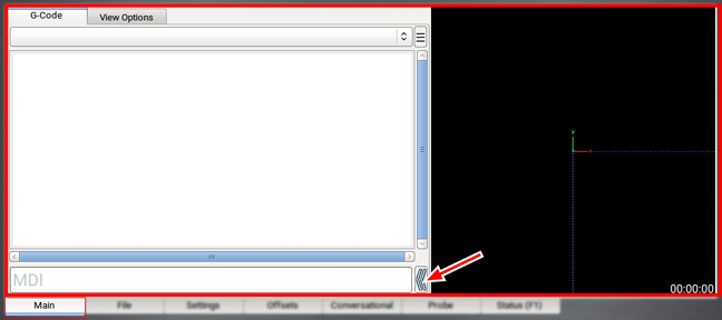
The Tool Path display shrinks.
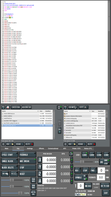
About the G-Code Tab
The G-Code tab displays the code of the currently loaded program file. Use the scroll bars to view the entire file. You can make the G-Code tab larger. For information, see "Expand the G-Code Tab".
PathPilot highlights certain lines of code of interest. When running a G-code program in single block mode, there may be as many as two lines of G-code highlighted, both with a different color:
-
Green Line Indicates the start line (the line from which PathPilot starts the program).
To change the start line, go to "Set a New Start Line".
-
Orange Line Indicates the line of code that PathPilot is currently executing.
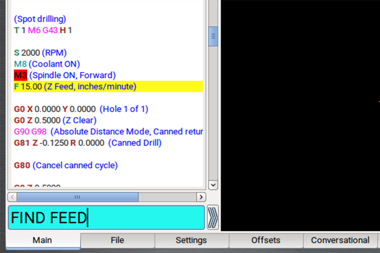
Search in the Code
You can use PathPilot to search the text of a G-code program file for specific numbers, codes, or other items of interest (like tools, feeds, and speeds).
To search in the code:
-
From Main tab, on the G-Code tab, select any line of code to use as a starting point.
-
In the MDI Line DRO field, type Find followed by one of the following:
-
Any text. PathPilot searches for instances of the specific number or code.
-
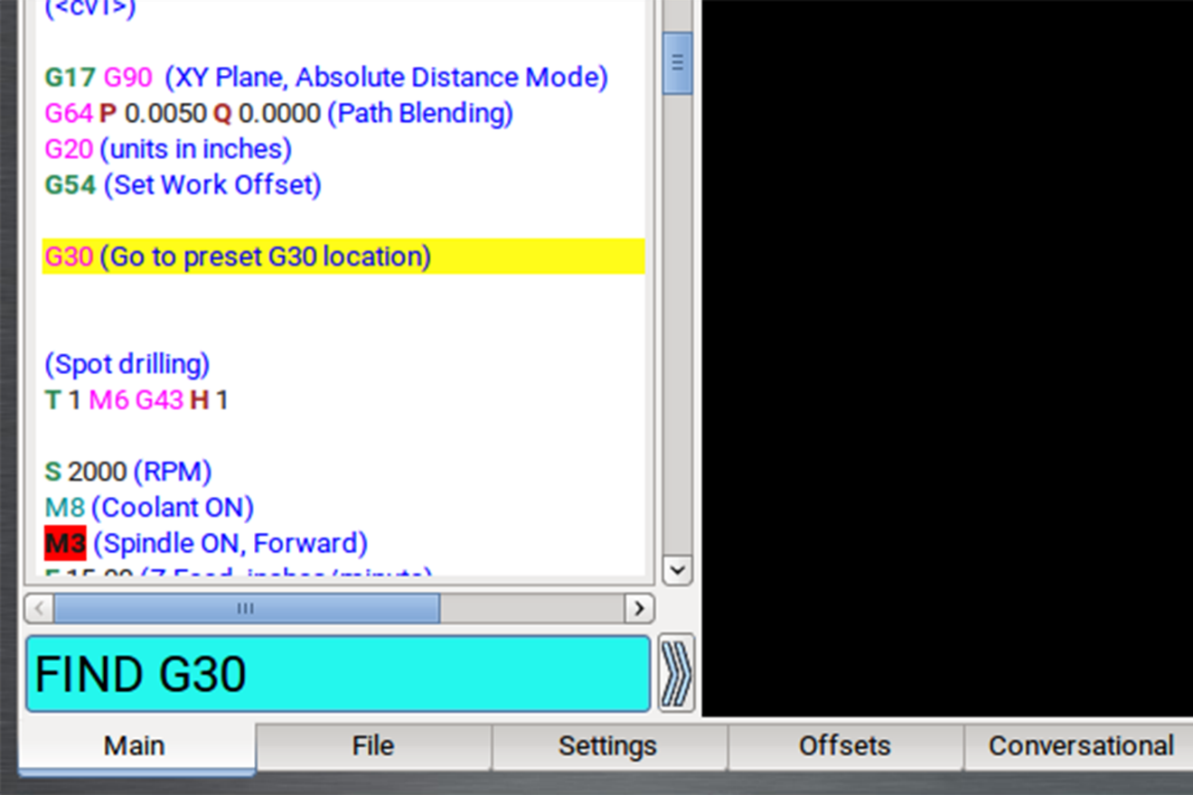
b. Feed. PathPilot searches for instances of the actual word Feed and any F G-code command.
c. Speed. PathPilot searches for instances of the actual word Speed and any S G-code command.
d. Tool. PathPilot searches for instances of the word Tool and any T G-code command.
NOTE: The find command is not case-sensitive.
-
Select the Enter key.
If PathPilot finds the information, the searched term is scrolled to and highlighted in the G-Code tab. -
(Optional) Select Enter.
PathPilot finds the next instance of the searched text. -
(Optional) Select Enter+Shift.
PathPilot finds the previous instance of the searched text.
NOTE: When the search reaches the end of the G-code file, it starts again from the beginning.
Set a New Start Line
The start line (the line from which PathPilot starts the program) is, by default, the first line of code in the program.
To set a new start line:
-
From the Main tab, on the G-Code tab, do one of the following:
-
Right-click any line in the program.
-
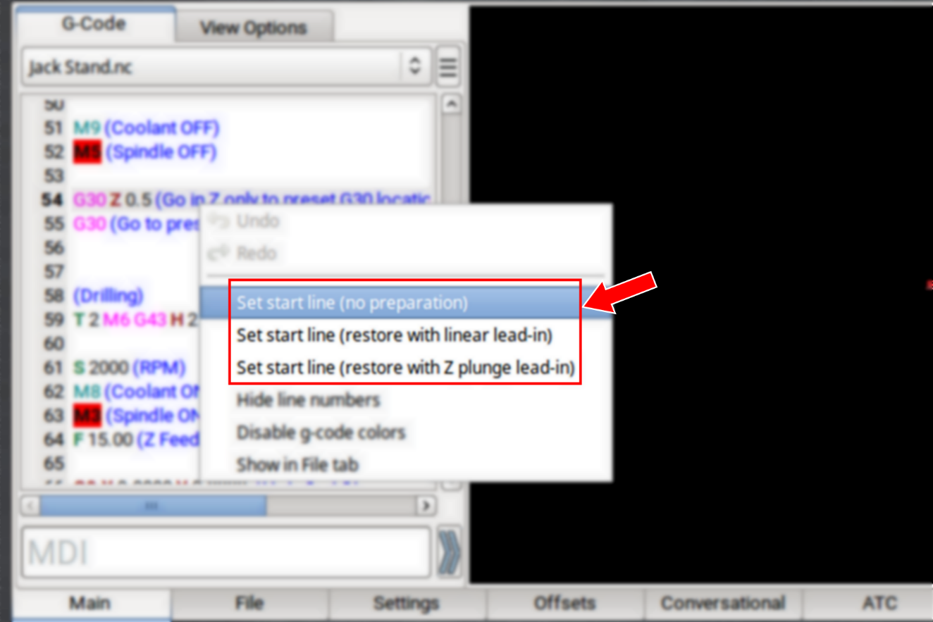
b. Tap the line. Then, select the Options menu.
-
Select the desired lead-in move. For information, see "Lead-In Moves".
Lead-In Moves
-
Set start line (no preparation) Keep the current tool in the spindle, with the current tool length applied. The machine executes the start line from the current position.
NOTE: We don't recommend this option for starting partway through a cut.
Example
-
Starting the program at a tool change.
-
Starting the program with a different tool in the spindle than the program calls for (like if your tool broke, which you've replaced, but you'd rather not edit the entire program or the tool table entry).
-
Set start line (restore with linear lead-in) Perform a tool change (as required). The machine rapids in X and Y, then Z to the current position, then feeds in a straight linear line to the start line position.
NOTE: This option assumes that the current position is the lead-in position.
Example
Quickly resuming work after stopping the program to make an adjustment to the machine setup (like clearing chips, removing an object, or turning on the coolant pump). Because the machine's already set up, you can position the tool near the stopping point.
-
Set start line (restore with Z plunge lead-in) Perform a tool change (as required). The machine rapids in Z to G30 clearance height, rapids in X and Y to the start line position, then feeds in Z to the start line position.
Example
Running a sub-section of a large program when the correct tool isn't loaded (and positioning the tool tip near the starting point is difficult, like with a long tool or fly cutter loaded). This option doesn't require you to jog to the exact lead-in position.
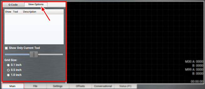
Change the View of the Tool Path Display
-
From the Main tab, do one of the following:
-
Right-click the Tool Path display.
-
b. Select the View Options tab.
-
Select a new view.
For information, see "About the Tool Path Display".
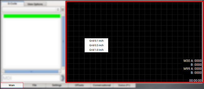
About the Tool Path Display
The Tool Path display is a graphical representation of the currently loaded G-code file's tool path. Depending on which programming mode you're in (G20 or G21), PathPilot defaults to one of the following grid line spacings:
-
G20 Mode 1/2 in. intervals
-
G21 Mode 5 mm intervals
In the Tool Path display, there are four different line types:
-
Dotted Blue Lines Indicate the boundary box (the ends of travel of the axes).
-
Red Lines Indicate the tool path as it is cut.
NOTE: The Tool Path display shows the program extents — the furthest points to which the tool will travel while running the program — of the currently loaded G-code file alongside the tool path lines.
-
White Lines Indicate the preview lines.
-
Yellow Lines Indicate the jogging moves.
To erase the jogging moves (yellow line) or the tool path (red lines), do one of the following:
-
Double-click anywhere in the Tool Path display.
-
Select Reset.
Use Conversational Programming
To create simple parts, use the conversational programming feature in PathPilot.
About Conversational Programming
PathPilot includes G-code generators intended to make simple G-code programs:
-
Programs for simple parts.
-
Programs for parts made up of a collection of simple features.
NOTE: For complex parts, or parts with complex shapes, we recommend you use a CAD/CAM program.
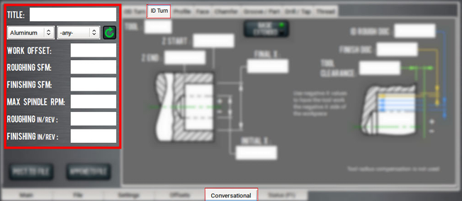
The Conversational tab is divided into two sections:
-
Parameters common to most operations, like speeds and feeds.
NOTE: DRO fields that are grayed out are not available for the specific conversational features.
-
Parameters specific to each operation, like part geometry.
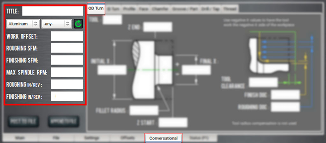
Create an Outside Diameter
Using conversational programming, you can program PathPilot to rough and finish three features: an outside diameter, a fillet (corner radius), or an adjacent face. For information, see "About OD Turning".
Before You Begin
Before you begin, you must verify that you enter the program values considering the following:
-
The value used in the Z End DRO field should be less than the value used in the Z Start DRO field.
-
The value used in the Filet Radius DRO field should be larger than the radius of the tool.
-
The tool is cutting both an outside diameter and a face — valid tools are limited to orientation 2 for a rear tool, and type 3 for a front tool.
-
The face is always on the headstock end of the diameter being cut.
-
The fillet calculation doesn't use cutter radius compensation: the middle of the fillet isn't on the true radius for a tool with a tip radius.
To create an outside diameter:
-
From the Conversational tab, select the OD Turn tab.
-
From the Conversational DROs group, set the parameters for the OD turning operation.
-
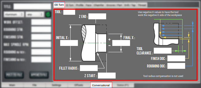
Work through the program-specific DRO fields:
-
In the Tool DRO field, type the currently selected tool as it's defined in the Tool Table window (on the Offsets tab).
This DRO field is a command value — it sets the tool number for a tool change at the start of the program.
-
b. In the Initial X DRO field, type the value of the stock's outside diameter.
NOTE: This DRO field is a reference value. It's also used with the Tool Clearance DRO field to locate some of the transitions between rapid and feed rate. If the values in the Initial X DRO field and the Final X DRO field are both positive, the tool works on the positive X side of the spindle center (the side away from you). If they're both negative, the tool works the negative side of the spindle (the side closer to you). It's an error if there's a positive and a negative value for each DRO field.
c. In the Final X DRO field, type the desired value of the part's final outside diameter.
d. In the Z Start DRO field, type the location of the stock's face.
NOTE: This DRO field is used with the Tool Clearance DRO field to set the transition between rapid and feed rate on some Z moves.
e. In the Z End DRO field, type the desired location of the part's face.
f. In the Fillet Radius DRO field, type the desired radius between the part's outside diameter and its face. For no radius, type 0.
NOTE: If you type a value that's less than the tip radius, PathPilot drives the cutter to the corner. If you type a value that's larger than the Z range (the distance between the location of the stock's face and the desired location of the part's face) or the X range (half of the distance between the stock's outside diameter and the desired value of the part's outside diameter), the fillet starts or ends outside of the stock perimeter, and it doesn't end at the specified X and Z locations.
g. In the Tool Clearance DRO field, type the distance required for clearance when the machine makes rapid movements between the stock's outside diameter its face. Because there's only one value used for X and Z moves, use the greater of the two clearances.
NOTE: Use larger values to begin; once you're familiar with how the program works, smaller values may save time. This DRO field is also sometimes used as a location for retracting the tool while making cutting passes.
h. In the Roughing DOC DRO field, type the desired amount of material to remove from the radius of the stock on each roughing pass. The depth of cut is adjusted to get the value used in the G-code.
i. In the Finish DOC DRO field, type the desired amount of material required for one finish pass (completed after roughing).
About OD Turning
Outside diameter turning is the process of removing material on the outside of a part.
OD Turning in PathPilot
During an OD turning routine, PathPilot does the following:
-
Roughing starts at the location typed in the Initial X DRO field, and incrementally cuts diameters at an adjusted depth of cut using the value typed in the Roughing DOC DRO field.
-
The finish diameter is started at the following location: (Final X + [2 × Finish DOC]). At this point, a single finishing pass is done at the value typed into the Finish DOC DRO field.
The finish pass starts at the +Z (tailstock) end of the outside diameter and feeds to the middle of the fillet.
NOTE: Since there is only one finish pass, the value in the Finish DOC DRO field isn't adjusted.
-
The tool retracts to the stock diameter.
-
The face finish pass is cut from the stock diameter to the end of the fillet.
Create an Internal Diameter
Using conversational programming, you can program PathPilot to cut a basic or extended internal diameter on a part. For information, see "About ID Turning".
Before You Begin
Before you begin, you must verify that you enter the program values considering the following:
-
Valid tool orientations are limited to type 2 for a front tool, and type 3 for a rear tool.
-
The tool path changes by 90° on the same side of the tool, so a form tool (narrow tip angle) and separate roughing DOCs are needed.
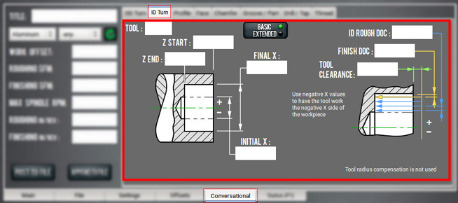
Basic Internal Diameters
To create a basic internal diameter:
-
From the Conversational tab, select the ID Turn tab.
-
From the Conversational DROs group, set the parameters for the ID turning operation.

-
Work through the program-specific DRO fields:
-
In the Tool DRO field, type the currently selected tool as it's defined in the Tool Table window (on the Offsets tab).
This DRO field is a command value — it sets the tool number for a tool change at the start of the program. -
In the Initial X DRO field, type the diameter of the pilot hole. Make sure that the diameter is large enough to clear the tool holder's X width.
-
In the Final X DRO field, type the desired final diameter of the internal diameter.
-
In the Z Start DRO field, type the location of the stock's face.
-
NOTE: This DRO field is used with the Tool Clearance DRO field to set the transition between rapid and feed rate on some Z moves.
e. In the Z End DRO field, type the desired final location for the part's face.
f. In the Tool Clearance DRO field, type the distance required to retract the tool and transition between rapid and cutting feed rate. Because there's only one value used for X and Z moves, use the greater of the two clearances.
NOTE: Use larger values to begin; once you're familiar with how the program works, smaller values may save time. Larger values bring the back of the tool holder closer to the ID wall on the end of facing cuts.
g. In the ID Rough DRO field, type the depth of material to cut on the radius of the bore. The depth of cut is adjusted to get the value used in the G-code.
h. In the Finish DOC DRO field, type the desired amount of material required for one finish pass on the ID, fillet, and face (completed after roughing).
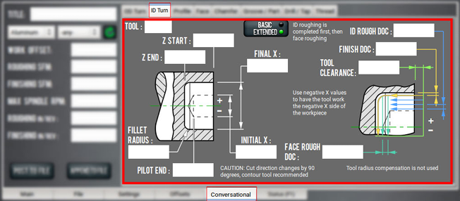
Extended Internal Diameters
To create an extended internal diameter:
-
From the Conversational tab, select the ID Turn tab.
-
Select the button to toggle from Basic to Extended mode.
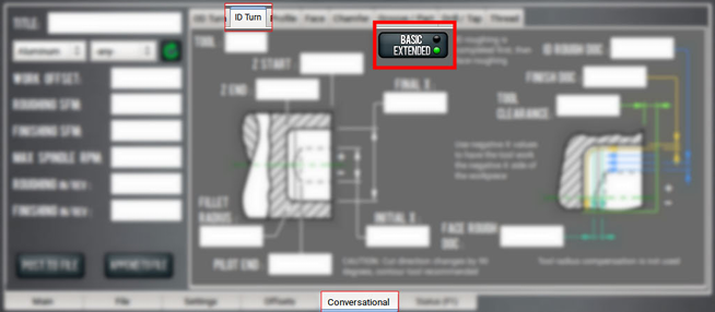
-
From the Conversational DROs group, set the parameters for the ID turning operation.
-
Work through the program-specific DRO fields:
-
In the Tool DRO field, type the currently selected tool as it's defined in the Tool Table window (on the Offsets tab).
This DRO field is a command value — it sets the tool number for a tool change at the start of the program. -
In the Initial X DRO field, type the diameter of the pilot hole. Make sure that the diameter is large enough to clear the tool holder's X width.
-
In the Final X DRO field, type the desired final diameter of the internal diameter. The value must be greater than twice the tool holder’s X width plus tool clearance.
-
In the Z Start DRO field, type the location of the stock's face.
-
NOTE: This DRO field is used with the Tool Clearance DRO field to set the transition between rapid and feed rate on some Z moves.
e. In the Fillet Radius DRO field, type the desired radius between the finished inside diameter and the face.
NOTE: The fillet calculation does not use CRC, so the middle of the fillet may not be on the true radius for a tool with a tip radius. Valid values are 0 or positive. Values larger than the Z range (Z START - Z END) or the X range ((INITIAL X - FINAL X) / 2) are valid, but will have a fillet start or end short of the finish locations, which may not be practical.
f. In the Z End DRO field, type the desired final location for the part's face.
g. In the Tool Clearance DRO field, type the distance required to retract the tool and transition between rapid and cutting feed rate. Because there's only one value used for X and Z moves, use the greater of the two clearances.
NOTE: Use larger values to begin; once you're familiar with how the program works, smaller values may save time. Larger values bring the back of the tool holder closer to the ID wall on the end of facing cuts.
h. In the ID Rough DRO field, type the depth of material to cut on the radius of the bore. The depth of cut is adjusted to get the value used in the G-code.
i. In the Face Rough DRO field, type the depth of material to cut on the internal face of the bore. The depth of cut is adjusted to get the value used in the G-code.
NOTE: The reverse or back cutting direction is sensitive to depth of cut. Form tools with a small angle between cutting edges allows for a larger depth of cut.
j. In the Finish DOC DRO field, type the desired amount of material required for one finish pass on the ID, fillet, and face (completed after roughing).
About ID Turning
Internal diameter turning is the process of removing material from the inside of a part.
ID Turning in PathPilot
There are two versions of ID turning in PathPilot: basic and extended. Both versions use CSS for spindle speed control and FPR for feed control. The fillet does not use CRC so the fillet will not follow a true radius for tools with a tip radius.
-
Basic Mode
Basic mode does one operation, which roughs and finishes from an initial pilot hole diameter to a final internal diameter without cutting a face at the bottom of hole. Use Basic mode for through holes or holes that don’t need a finished face. Each pass ends at Z End.
Roughing starts at the pilot hole diameter (the value in the X Start DRO field), and incrementally cuts diameters with an adjusted depth of cut until the start of the finish diameter (X End - [2 × Finish DOC]). Finishing is done in one pass.
-
Extended Mode
Extended mode does three operations: ID roughing, face roughing, and an ID, fillet, and face finish pass. The extended ID roughing passes stop at the bottom of the pilot hole in order to prevent engaging too much of the tool cutting edge. Once the rough ID is cut to the pilot hole bottom, rough facing is started. There are two DRO fields for depth of cut, since, depending on the tool geometry, ID roughing and face roughing may need different depth of cuts.
For each face pass, the tool tip cuts to the hole center + Tool Clearance which requires a rough hole diameter (which was cut in the first operation) that is a little more than twice the tool’s X width. Caution is needed to prevent hitting the back of the tool holder on the side of the hole.
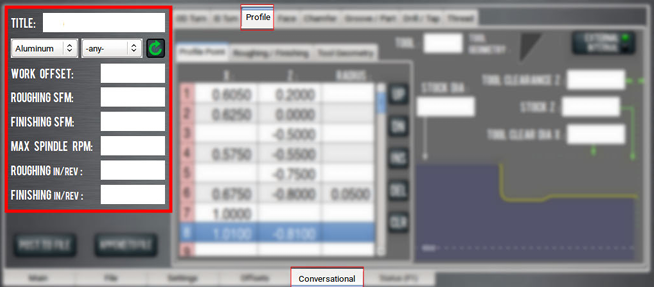
Create a Profile on a Part
Using conversational programming, you can program PathPilot to rough and finish an arbitrary internal or external profile on a part. For information, see "About Profiling".
Before You Begin
Before you begin, you must verify that you enter the program values considering the following:
-
The Tool Clear Dia X DRO field has a value of smaller diameter than first X value on the Profile Point table.
-
An internal tool is indicated in the Tool DRO field.
Complete the following steps in the order listed:
Describe the Stock
-
From the Conversational tab, select the Profile tab.
-
(Optional) To create an internal profile, select the button to toggle from External mode to Internal mode.
-
From the Conversational DROs group, set the parameters for the profiling operation.
-
Work through the program-specific DRO fields:
-
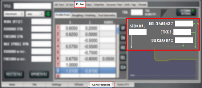
In the Stock Dia DRO field, type the diameter of the stock.
-
In the Tool Clearance Z DRO field, type the Z value for the tool clearance on the Z-axis.
Tool Clearance Z is the Z plane the tool goes from rapid to feed. -
In the Stock Z DRO field, type the starting Z value for the profile.
-
In the Tool Clear Dia X DRO field, type the X value — as a diameter — for the tool clearance on the X-axis.
-
For External Profiles You must make sure the value typed in the Tool Clear Dia X DRO field is a larger diameter than the value typed in the Stock Dia DRO field.
-
For Internal Profiles You must make sure the value typed in the Tool Clear Dia X DRO field is a smaller diameter than the first diameter (specified in the Profile Point table).
-
-
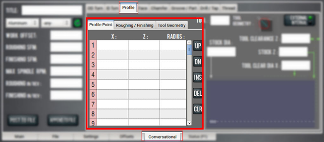
Identify the Profile Points
Use the Profile Point table to describe the point-to-point values of a profile — from a larger Z value to a smaller Z value. As you work through the Profile Point table, PathPilot displays a graphical representation of the profile on your part.
Click on any segment in the graphic to highlight the corresponding row in the Profile Point table. Alternately, you may click on any row in the Profile Point table to highlight the corresponding segment in the graphic.
Point the mouse toward any area in the graphic and use the scroll wheel to zoom in and out to enlarge small features. To quit zooming, either select the Esc key or select another line in the Profile Point table.
To identify the profile points:
-
Select the Profile Point tab.
-
In the Profile Point table, type the X and Z values for the profile. X values are in diameters terms. The X field is expressed in terms of X+ cutting (X- G-code will properly be generated if the tool selection calls for it).
NOTE: If the value is unchanged from the previous row in the Profile Point table, PathPilot assumes the value is repeated. If you are using the same value, you can leave the cell empty.
-
(Optional) In the Radius column, type a value to X and Z end points to create an arc.
-
For a Center Point Above and/or to the Right of the Start Point Type a positive radius value.
-
For a Center Point Below and/or to the Left of the Start Point Type a negative radius value.
-
Identify the Tool
-
In the Tool DRO field, type the number of the tool to use for creating the profile.
Tool Geometry displays a graphical representation of the selected tool. -
On the graphical representation of the profile on your part, make sure there are no red line segments. If there are red line segments, you must specify a new tool or edit the fields in the Profile Point table.
A red line segment indicates that the geometry of the selected tool cannot cut the programmed angle without gouging the part profile — typically, when feature entry or exit angles are too steep for the tool geometry to clear.
The back angle of the tool will not clear the entry to the arc feature.
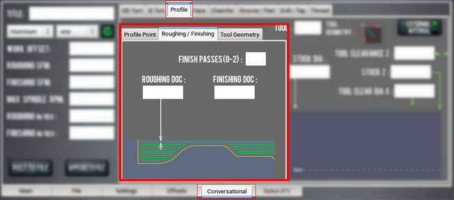
Identify the Roughing and Finishing
Use the Roughing / Finishing tab to describe the required roughing and finishing for the part’s profile.
NOTE: You can use only roughing or only finishing. It is an error if all three of the following DRO fields are empty: Finishing Passes, Roughing DOC, and Finishing DOC.
To identify the roughing and finishing:
-
Select the Roughing / Finishing tab.
PathPilot updates the graphical representation of the profile depending on which DRO field you select:-
Select inside the Roughing DOC DRO field to display a roughing graphic.
-
b. Click inside the Finishing DOC DRO field or the Finish Passes DRO field to display a finishing graphic.
-
In the Roughing DOC DRO field, type the depth of cut for each roughing pass.
NOTE: The default value is 0.02 inches.
-
In the Finishing DOC DRO field, type the depth of cut for each finishing pass.
NOTE: The default value is 0.003 inches.
4. In the Finishing Passes DRO field, type the number – from 0-2 – of finishing passes.
NOTE: The default value is 2 (passes).
A finishing pass is a continuous pass from the start of the profile (toward the tailstock) to the end of the profile (toward the headstock).
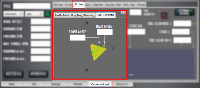
Describe the Tool Geometry
Use the Tool Geometry tab to describe the front and rear profiling angles. Because there are many tool and tool holder geometries, the Tool Geometry tab allows you to properly describe each tool and avoid part gouging.
To describe the tool geometry, you must first determine the cutting direction: either X+ or X-, based on the tool orientation and an external or internal profile.
For example, if you are cutting an external profile on a part and have a tool orientation of 2, PathPilot creates X+ G-code.
Use the following table to determine the cutting direction:
|
Cutting Direction |
Internal or External |
Tool Orientation |
|
X+ (typically, while using a turret) |
External |
1, 2, 6 |
|
Internal |
3, 4, 8 |
|
|
X- (typically, while using a quick-change tool post) |
External |
3, 4, 8 |
|
Internal |
1, 2, 6 |
To describe the tool geometry:
-
X+ Cutting Tool In the Front Angle DRO field and the Back Angle DRO field, type the value of the tool geometry expressed as a negative angle in the counterclockwise direction from 0˚.
NOTE: The Tool Geometry graphic preview (to the right of the Tool DRO field) updates as angles are changed.
-
X- Cutting Tool In the Front Angle DRO field and the Back Angle DRO field, type the value of the tool geometry expressed as a negative angle in the clockwise direction from 0˚.
About Profiling
The profile is created from a list of points that describes the part geometry. A profile can have both forward (toward the tailstock) and rear (toward the headstock) facing features, and can also start behind the highest Z plane (the feature that is closest to the tailstock).
On the Profile tab, you can also specify things like:
-
Tool geometry
-
Feeds and speeds
-
Finish depth
-
Number of finish passes
-
Roughing depth of cut (roughing DOC)
Create a Face on a Part
Using conversational programming, you can program PathPilot to cut a face with tool paths from the stock's outer diameter to the spindle center or an inner diameter (with each pass progressing in Z toward the headstock). For information, see "About Facing".
Before You Begin
Before you begin, you must verify that you enter the program values considering the following:
-
To cut with a rear tool, the values used in the Initial X DRO field and the Final X must be positive. The tool works on the positive X side of the spindle center (the side away from you).
-
To cut with a front tool, the values used in the Initial X DRO field and the Final X must be negative. The tool works on the negative side of the spindle (the side closest to you).
-
The value used in the Roughing DOC DRO field must be positive.
-
The value used in the Finish DOC DRO field must be positive.
-
Spindle speed control: CSS.
-
Feed rate control: FPR.
To create a face on a part:
-
From the Conversational tab, select the Face tab.
-
From the Conversational DROs group, set the parameters for the facing operation.
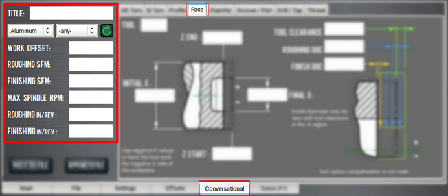
-
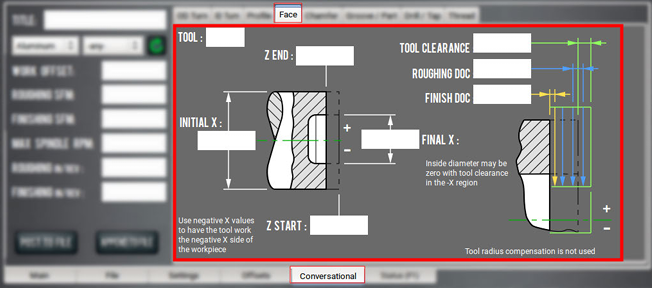
Work through the program-specific DRO fields:
-
In the Tool DRO field, type the tool number for use with the program. This sets the tool number for a tool change at the start of the program.
-
In the Initial X DRO field, type the stock diameter. This value is also used with the value in the Tool Clearance DRO field to locate some of the transitions between rapid and feed rate.
-
In the Final X DRO field, type the location of the face inside diameter. The tool path goes beyond this diameter by the tool clearance. For tools with a tip radius, the control point and face contact point aren't the same, so the tool clearance value, if greater than the tool tip radius, can be used to extend the path to the contact point.
-
In the Z Start DRO field, type the location of the stock face. Roughing passes start here. It is also used with Tool Clearance to set the transition between rapid and feed rates on some moves.
-
In the Z End DRO field, type the finished face location.
-
In the Tool Clearance DRO field, type the desired space required for tool retracting and transitions between rapid and cutting feed rate. Since there's one value used for X and Z moves, set the value to the greater of the two clearances. Larger values may be safer, but brings the back of the tool holder closer to the inner diameter wall on the end of facing cuts. Smaller values may save time once you're familiar with how well the program works.
-
In the Roughing DOC DRO field, type the depth of the material being cut. This depth of cut is adjusted to get the value used in the G-code.
-
In the Finish DOC DRO field, type the desired amount of material required for one finish pass (after roughing).
-
About Facing
During a facing routine, PathPilot does the following:
-
Rough facing starts at Z Start and incrementally cuts at the depth of cut until the start of the finish face pass (Z End + Finish DOC).
-
The start of each pass is at the Initial X diameter + Tool Clearance and moves in the minus X direction until the Final X diameter – Tool Clearance is reached.
If the value in the Final X DRO field is zero, the end of the pass will go beyond the spindle center. -
Finishing is done in one pass at the value entered into the Finish DOC DRO field.
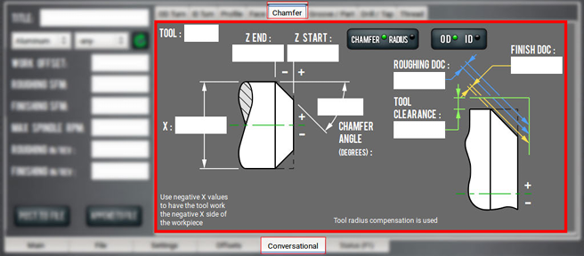
Create a Chamfer or Radius on a Part
Using conversational programming, you can program PathPilot to cut a chamfer, taper, or corner radius. For information, see "About Chamfer and Radius".
Before You Begin
Before you begin, you must verify that you enter the program values considering the following:
-
Uses cutter compensation (G41, G42), so that tools with a nose radius can cut to the correct profile.
-
Radii are limited to 90° arcs that start on the outside diameter (the Initial X DRO field and the Z End DRO field). Be careful when using chamfer angles less than 30° or greater than 60°, due to the extra travel involved in traversing the tool clearance space at an angle. The path may take the tool into the chuck, spindle, or adjacent workpiece features.
-
The value used in the Rouging DOC DRO field must be positive.
-
The value used in the Finish DOC DRO field must be positive.
-
Spindle speed control: CSS.
-
Tool feed control: FPR.
To create a chamfer or radius on a part:
-
From the Conversational tab, select the Chamfer tab.
-
From the Conversational DROs group, set the parameters for the chamfer or radius operation.
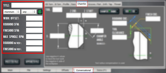
-
Work through the program-specific DRO fields:
-
In the Tool DRO field, type the tool number for use with the program. This sets the tool number for a tool change at the start of the program.
-
In the X DRO field, type the stock diameter. This value is also used with the Tool Clearance DRO field to locate some of the transitions between rapid and feed rates.
-
In the Z Start DRO field, type the stock face or the end of the chamfer or radius. This value is also used with the Tool Clearance DRO field to set the transition between rapid and feed rates on some Z moves.
-
In the Z End DRO field, type the location of the start of the chamfer or radius. The Z width of a chamfer or the radius of a corner equals (Z End - Z Start).
-
(Optional) In the Chamfer Angle DRO field, type the angle between the workpiece centerline and the chamfer.
-
In the Tool Clearance DRO field, type the desired space beyond the stock outside diameter and face that's required for some movements to clear the workpiece. Since there is one value used for X and Z moves, set the value to the greater of the two clearances. Larger values may be safer; smaller values may save time once you're familiar with how well the program works. This field is also sometimes used as a location for retracting the tool while making cutting passes.
-
In the Rouging DOC DRO field, type the depth of cut during roughing. The depth of cut is adjusted. In this case, the roughing range is the distance from the workpiece corner (the intersection of the face and outer diameter) and the closest point on the chamfer or radius minus the finish depth of cut.
-
In the Finish DOC DRO field, type the desired amount of material required for one finish pass (after roughing).
-
About Chamfer and Radius
During a routine to create a chamfer or a radius, PathPilot does the following:
-
Roughing starts at the corner of X and Z Start in adjusted depth of cut increments perpendicular to the chamfer angle or incremental arcs for radius.
-
The last roughing pass leaves enough material for the finish pass; finishing is done with a single pass.
-
Passes start and end on the perimeter of the tool clearance space, which is set by adding the tool clearance DRO value to the stock OD, X, and the face location, Z Start.
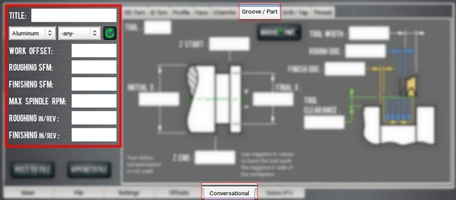
Create a Groove or Part a Workpiece
Using conversational programming, you can program PathPilot to create a groove or to part a workpiece from stock. For information, see "About Grooving and Parting".
Before You Begin
Before you begin, you must verify that you enter the program values considering the following:
-
Grooving paths are based on Z Start and Z End values:
-
If the value in the Z Start DRO field is greater than the value in the Z End DRO field, the tool’s control point is set to the +Z side of the tool.
-
If the value in the Z Start DRO field is less than the value in the Z End DRO field, the control point is set to the -Z side of the tool.
-
-
Groove roughing is done with plunge cuts in the X direction. Each plunge is incremented in the Z direction from Z Start ± Finish DOC to Z End ± (Tool Width + Finish DOC).
-
Even though a grooving/parting tool may be considered to have two tips, valid tool orientation is limited to:
-
Groove on the negative side of Z Start, Back Tool = Type 1
-
Groove on the positive side of Z Start, Back Tool = Type 2
-
Groove on the positive side of Z Start, Front Tool = Type 3
-
Groove on the negative side of Z Start, Front Tool = Type 4
-
Part on the negative side of Z Start, Back Tool = Type 1
-
Part on the negative side of Z Start, Front Tool = Type 4
-
-
CSS is used for spindle speed control.
-
FPR is used for feed rate control.
-
CRC is not used.
To create a groove on a part, or to part a workpiece:
-
From the Conversational tab, select the Groove/Part tab.
-
From the Conversational DROs group, set the parameters for the grooving or parting operation.
-
If required, toggle the Groove/Part button. Then, do one of the following:
-
Go to "Create a Groove on a Part".
-
Go to "Part a Workpiece from the Stock".
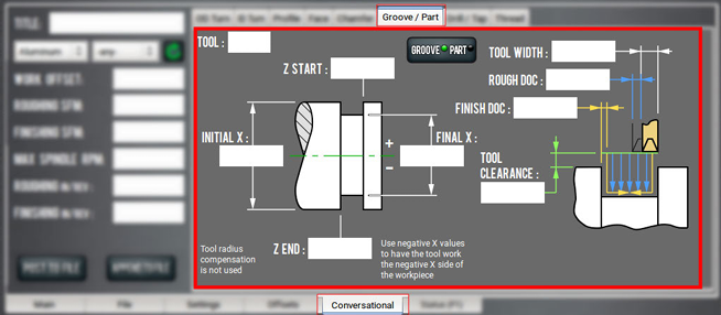
Create a Groove on a Part
Work through the program-specific DRO fields:
-
In the Tool DRO field, type the tool number for use with the program. This sets the tool number for a tool change at the start of the program.
-
In the Initial X DRO field, type the stock diameter. This value is also used with the Tool Clearance DRO field to locate some of the transitions between rapid and feed rates.
-
In the Final X DRO field, type the diameter of the new groove bottom or the end of the parting.
-
In the Z Start DRO field, type the location of the groove start. For parting, this field sets the location of the +Z side of the slot.
-
In the Z End DRO field, type the location of the groove end.
-
In the Tool Width DRO field, type the groove or parting tool's width.
-
In the Rough DOC DRO field, type the depth of the material being cut. In this case, for groove, it is the Z offset for each plunge cut. The depth of cut is adjusted. Valid values are positive and normally should be less than the full depth width of the tool tip (usually the distance between tip radii centers).
-
In the Finish DOC DRO field, type the desired amount of material required for one finish pass (after roughing).
-
In the Tool Clearance DRO field, type the desired space beyond the stock outside diameter for rapid movements to clear the workpiece. Larger values may be safer; smaller values may save time once you're familiar with how well the program works. This field is also sometimes used as a location for retracting the tool between cutting passes.
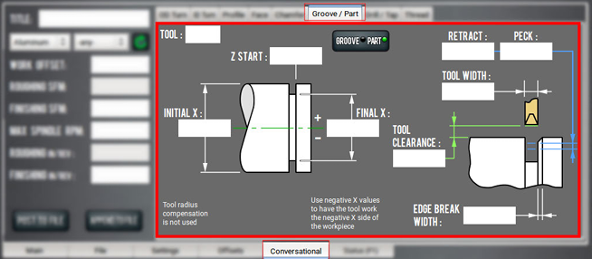
Part a Workpiece from the Stock
Work through the program-specific DRO fields:
-
In the Tool DRO field, type the tool number for use with the program. This sets the tool number for a tool change at the start of the program.
-
In the Initial X DRO field, type the stock diameter. This value is also used with the Tool Clearance DRO field to locate some of the transitions between rapid and feed rates.
-
In the Final X DRO field, type the diameter of the new groove bottom or the end of the parting.
-
In the Z Start DRO field, type the location of the groove start. For parting, this field sets the location of the +Z side of the slot.
-
In the Tool Width DRO field, type the groove or parting tool's width.
-
In the Tool Clearance DRO field, type the desired space beyond the stock outside diameter for rapid movements to clear the workpiece. Larger values may be safer; smaller values may save time once you're familiar with how well the program works. This field is also sometimes used as a location for retracting the tool between cutting passes.
About Grooving and Parting
-
Groove finishing is done with a plunge cut down the Z End side.
-
When the tool reaches the bottom, the tool is moved in the Z direction toward the center of the groove, then retracts.
-
The tool is plunged on the Z Start side of the groove, then again is moved in Z toward the groove center and retracted. This requires a grooving tool, which can side cut. Part does one plunge cut at Z Start. The tool’s control point is on the +Z side of the tool. The plunge cannot be set to go beyond the spindle center (X = 0).
Create Holes on a Part or Tap a Hole
Using conversational programming, you can program PathPilot to drill holes on a part, or use rigid tapping to thread holes on a part. For information, see "About Drilling and Tapping".
Before You Begin
Before you begin, you must verify that you enter the program values considering the following:
-
The value used in the Z Start DRO field must be larger than the value in the Z End DRO field.
-
For tapping, the value used in the Z End DRO should allow for extra threading while the spindle comes to a stop and reverses.
-
The value used in the Peck Depth DRO field needs a direction, so should have a negative value.
-
Drilling is limited to the -Z direction, toward the spindle.
-
Use the RPM DRO field instead of CSS.
To create holes on a part, or to tap a hole:
-
From the Conversational tab, select the Drill/Tap tab.
-
From the Conversational DROs group, set the parameters for the drilling or tapping operation.
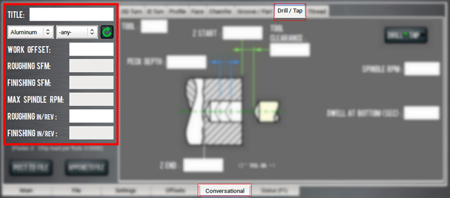
-
If required, toggle the Drill/Tap button. Then, do one of the following:
-
Go to "Create a Hole on a Part".
-
Go to "Create Threads in a Hole".
Create a Hole on a Part
Work through the program-specific DRO fields:
-
In the Tool DRO field, type the tool number for use with the program. This sets the tool number for a tool change at the start of the program.
-
In the Z Start DRO field, type the stock face location. This field is also used with the Tool Clearance DRO field to set the transition between rapid and the feed for drilling or tapping.
-
In the Z End DRO field, type the final depth. This is the location where the drill feed stops and optionally dwells.
-
In the Peck Depth DRO field, type an incremental depth for retracting the drill to clear chips from the hole, if required. If drilling the hole doesn't need a peck, type 0. To make each peck depth equal, the value is adjusted to fit an integer number of pecks within the hole depth.
-
In the Tool Clearance DRO field, type the desired space required for tool retraction and transitions between rapid and cutting feed rate.
-
In the Spindle RPM DRO field, type the RPM (G97) desired.
-
In the Dwell at Bottom (Sec) DRO field, type the length of time that Z motion should pause so that the drill can finish cutting the hole bottom before retracting.
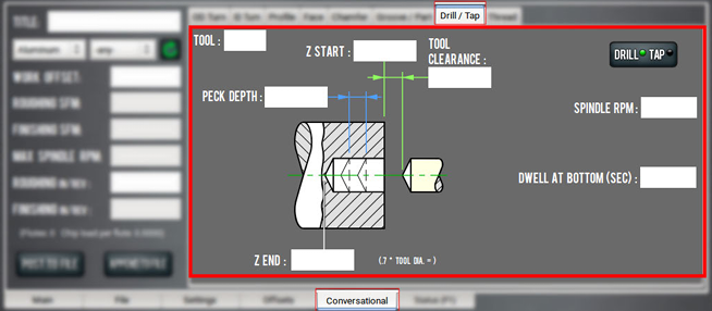
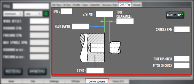
Create Threads in a Hole
Work through the program-specific DRO fields:
-
In the Tool DRO field, type the tool number for use with the program. This sets the tool number for a tool change at the start of the program.
-
In the Z Start DRO field, type the stock face location. This field is also used with the Tool Clearance DRO field to set the transition between rapid and the feed for drilling or tapping.
-
In the Z End DRO field, type the final depth. This is the location where the spindle rotation is reversed.
-
In the Peck Depth DRO field, type an incremental depth for retracting the drill to clear chips from the hole, if required. If drilling the hole doesn't need a peck, type 0. To make each peck depth equal, the value is adjusted to fit an integer number of pecks within the hole depth.
-
In the Tool Clearance DRO field, type the desired space required for tool retraction and transitions between rapid and cutting feed rate.
-
In the Spindle RPM DRO field, type the RPM (G97) desired.
-
In the Threads/Inch (/mm) DRO field, type the Z motion to spindle ratio that matches the thread pitch required. This field is also used with the Pitch (Inches) DRO field, so entering a value in either field calculates and inserts a value in the other.
-
In the Pitch (Inches) DRO field, type the Z motion to spindle ratio that matches the required thread pitch. This field is also used with the Threads/Inch (/mm) DRO field, so entering a value in either field calculates and inserts a value in the other.
About Drilling and Tapping
Drilling
-
For feed rate control, drill uses a millimeter or inch feed per revolution (G95) to feed from Z Start + Tool Clearance until Z End.
-
Rapids back to Z Start + Tool Clearance.
Dwell allows a pause for the drill to stay at Z End long enough to cut a full revolution at the bottom of the hole (rather than immediately retracting the drill, which could leave an irregular bottom).
Pecking can help clear chips before they bind in the hole during drilling. The peck motion retracts to Z Start + Tool Clearance on each cycle.
NOTE: Due to motion control limits, the retract to Z Start + Tool Clearance may not retract fully before starting the next drilling feed. You must verify that the pecking retract motion meets requirements for your application.
Tapping
Tap uses electronic gearing (G33.1, Rigid Tapping) to lock the Z-axis and spindle motion together for rigid tapping.
-
Tapping starts with the tap at Z Start + Tool Clearance.
-
Z motion waits until the spindle encoder index is tripped. Then, the gears are engaged and Z feeds at the rate set by the pitch or threads per unit (TPU) and spindle encoder count. The Z motion follows the spindle motion no matter what the spindle does.
-
For tapping, the spindle is run forward until Z End is reached, the spindle is reversed, which causes it to slow to a stop, then reverse. During this time, the tap continues to follow the spindle motion and continues to make threads until the spindle reverses.
NOTE: These extra threads needs to be considered when setting the Z End DRO field.
-
The reverse motion continues until reaching Z Start + Tool Clearance where the gearing is disengaged.
Create Threads on a Part
Using conversational programming, you can program PathPilot to single point an external or an internal thread on an existing outer diameter. For information, see "About Threading".
Before You Begin
Before you begin, you must verify that you enter the program values considering the following:
-
The value used in the Z Start DRO field must be larger than the value used in the Z End DRO field.
-
The value used in the Depth of Cut DRO field must be positive.
To create threads on a part:
-
From the Conversational tab, select the Thread tab.
-
From the Conversational DROs group, set the parameters for the threading operation.
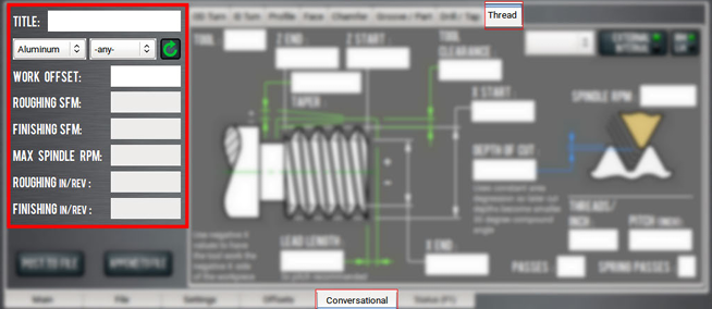
-
If required, toggle the External/Internal button or the RH/LH button.
-
Work through the program-specific DRO fields:
-
In the Tool DRO field, type the tool number for use with the program. This sets the tool number for a tool change at the start of the program.
-
In the X Start DRO field, type the existing major diameter for external threads, or minor diameter for internal threads.
-
In the X End DRO field, type the location of the new outside diameter.
-
In the Z Start DRO field, type the stock face location. This value is also used with the Tool Clearance DRO field to set the transition between rapid and feed rate on some Z moves.
-
In the Z End DRO field, type the final thread Z location.
-
In the Tool Clearance DRO field, type the desired space beyond the stock outside diameter that's required for rapid movements to clear the workpiece. This sets the starting X diameter of the thread cycle return path. Larger values may be safer; smaller values may save time once you're familiar with how well the program works.
-
In the Lead Length DRO field, type the required length during the start of the cutting path that allows the motion to stabilize before cutting material. The start of a cutting pass waits for the spindle encoder index to trip; when it does, the Z motion tries to instantly match the spindle speed, but actually needs time to accelerate and match the spindle encoder count. This value must be a compromise between spindle speed, thread pitch, and workpiece clearance.
-
From the Thread Table drop-down menu, select the value for the thread. The threads listed in this menu follow the current unit setting (inch or millimeter). Once you make a selection, the data for that thread is entered into the appropriate DRO fields.
-
NOTE: The values entered in these tables assume a full form thread tool. If you're using a fine point threading tool to cut coarse threads, you must modify the root diameter to account for the smaller tool nose radius of the fine point threading tool.
i. In the Spindle RPM DRO field, type the spindle rpm.
j. In the Depth of Cut DRO field, type the depth of material being cut. Each pass is incremented based on a calculation of the area of the material being removed. This allows for a constant tool load for each pass.
k. In the Threads/Inch (/mm) DRO field, type the number of threads per inch (or millimeter).
l. In the Pitch (Inch) DRO field, type the distance per thread.
m. In the Passes DRO field, type the number of successive passes to cut the thread.
n. In the Spring Passes DRO field, type the number of extra passes at full thread depth. We suggest using this to clean up the thread and compensate for any material deflection during thread cutting.
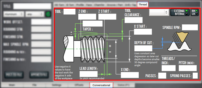
About Threading
Thread is based on the G76 Threading Cycle. This canned cycle contains a lead-in, cut, lead out, and return path for each threading pass. Each cycle is incrementally offset in X and Z to account for a 30° software compound angle. The offset is calculated such that the each pass cuts the same amount of material by cross sectional area. The first pass has the most X displacement, and this decreases with each pass.
Machine Settings and Accessories
Before running a G-code program, you must first make sure that the machine settings are properly configured.
Enable an Internet Connection
If desired, you can enable an internet connection on your PathPilot controller. An internet connection allows you to receive automatic PathPilot updates and transfer files with PathPilot HUB instead of a USB drive.
To enable an internet connection:
-
From the PathPilot interface, on the Status tab, select Internet.
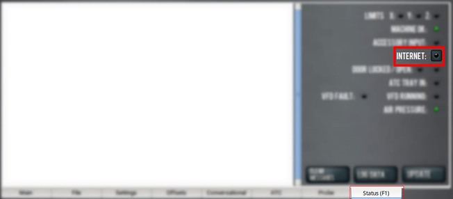
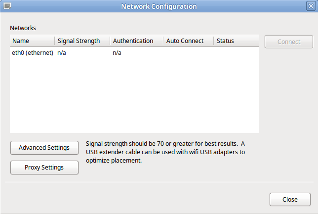
The Network Configuration dialog box displays.
-
From the Network Configuration dialog box, in the Networks list, select the network you want to use. Then, select Connect.
NOTE: Wi-Fi connection signal strengths are indicated on a scale of 0 to 100, with 100 being the strongest. PathPilot continually refreshes the signal levels to help you find the best placement for your Wi-Fi network adapter. Ethernet connections are indicated by a prefix in the following format: eth[NUMBER]. For example, eth1.
The PathPilot operating system connects to the internet using the network you specified. It continues to detect and connect to the Wi-Fi network, even after power cycles.
-
Once connected, you can use PathPilot HUB and automatic updates features. Depending on what you want, see the following procedures:
Enable Automatic Updates
NOTE: Automatic updates require an internet connection. If you haven't yet enabled it, go to "Enable an Internet Connection".
If desired, you can enable automatic updates for PathPilot.
To enable automatic updates:
-
From the PathPilot interface, on the Status tab, select Update.
The Software Update dialog box displays.
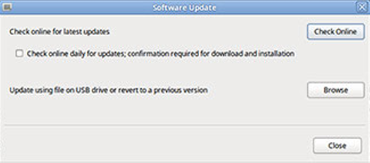
-
From the Software Update dialog box, select the Check online daily for updates; confirmation required for download and installation checkbox.
-
Select Close.
When future updates are available, the Status tab displays a notification.
Change the Network Name
If you're connected to a network using either the Ethernet jack or the (optional) Wireless Network Adapter (PN 38207), the PathPilot controller appears on your network as network-attached storage. The default network name of the controller is TORMACHPCNC.
To change the network name:
-
From the Network Name field, type a new network name.
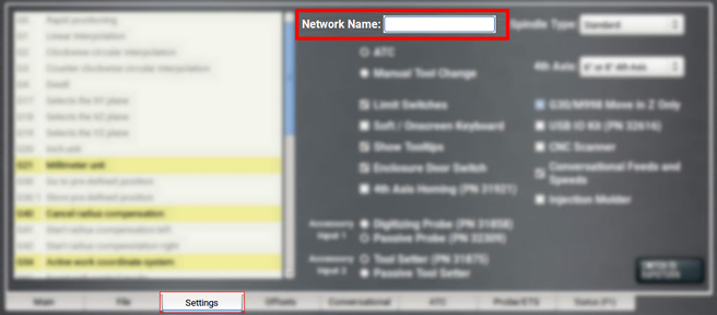
NOTE: The network name must be unique within your network.
-
Select the Enter key.
-
For the change to take effect, you must restart the controller.
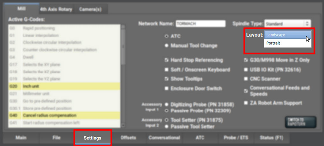
Change the Screen Orientation
A vertical orientation for 1920 × 1080 monitors is supported in PathPilot v2.10.0 and later. For more information on the portrait layout, go to "About Portrait Screen Layout".
To change the screen orientation:
-
From the PathPilot interface, on the Settings tab, select Portrait from the Layout drop-down menu. Restart the controller.
-
Rotate the monitor to the portrait orientation. You can rotate it either left or right, depending on what's easier for your setup.
-
While the controller is restarting, specify which direction you've rotated the monitor. Select Apply. If the result is unexpected, click Restore Previous Configuration on the confirmation dialog and choose a rotation direction again.
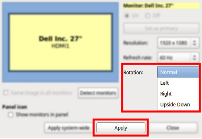
The controller restarts in portrait layout.
About Portrait Screen Layout
Portrait layout provides some key advantages:
-
A larger tool path window that's always visible at the top of the screen, regardless of which tab you have active.
-
A wider G-code window to more easily read the loaded G-code file and, if enabled, line numbers.
-
The tool path window's view options are always visible for much easier access.
-
When browsing G-code files using the File tab, file previews display on the top portion of the screen.
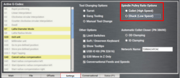
Specify the Spindle Pulley Option
-
From the Settings tab, select one of the following:
-
Collet (High Speed)
-
Chuck (Low Speed)
-
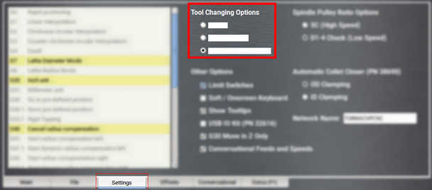
Specify the Tool Change Method
When PathPilot finds an M06 command in a G-code program, it has different behaviors depending on the specified tool change method.
To specify the tool change method:
-
From the Settings tab, select the appropriate tool change method for your machine.
About Turret Tool Changes
T commands T01 through T08 cause the turret to index (regardless of current machine position) and the offsets for the requested tool are applied. With the turret setup, tool numbers higher than eight are still available, and a T command of, for example, T09 does not cause turret rotation but does apply the offsets for tool 9. It is possible to mount a parting tool or gang of drills to the lower portion of the carriage and assign tool numbers higher than eight to these tools.
The machine does not automatically retract to G28 or G30 position before a tool change. You must program the machine to a safe position before executing a T command. If generating code using the conversational features of the control, a G30 is inserted before each tool change command.
About Gang Tool Changes
If the gang option is selected, the T command simply applies the offsets for the selected tool. Unlike the manual tool change option, T commands with the gang option selected doesn't pause the program during the tool change. Offsets are applied nearly instantaneously, and machining resumes automatically during part program execution.
About Manual Tool Changes
The manual tool change option causes the machine to pause at the T command during G-code program execution. This allows you to manually change tools on a quick-change tool post. After changing tools, selecting Cycle Start resumes program execution with the new tool offsets applied. When the machine is paused waiting for a manual tool change in the middle of a G-code program, the light on the Cycle Start button flashes, and the tool label flashes with the requested tool number.
About Mixed Tooling Changes
When mixing turret or gang tools with quick-change tool post mounted tools, there are two choices:
-
If you select the turret or gang setting, the machine won't automatically pause for manual changes of quick-change tool post tools. You must program these manual M01 stops.
NOTE: We recommend this option.
-
If you select the quick-change tool post option, you must select Cycle Start to confirm both manual and turret/gang changes.
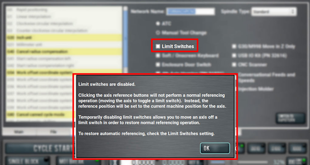
Disable Limit Switches
To provide a temporary workaround for a malfunctioning limit switch circuit, you can disable the limit switches. For information, see About Limit Switches.
NOTE: By default, the Limit Switches checkbox is selected.
To disable limit switches:
-
From the Settings tab, clear the Limit Switches checkbox.
-
Select OK.
The machine completes a unique referencing procedure after selecting the axis reference buttons: rather than moving each axis to the end of its travel, the reference position is set as the machine's current position.
Tip! This is useful for troubleshooting, because you're now able to move the axis.
Limit G30 Moves
You can limit G30 moves so that only the Z-axis moves. For information, see "About G30".
To limit G30 moves:
-
From the Settings tab, select G30 Move in Z Only.
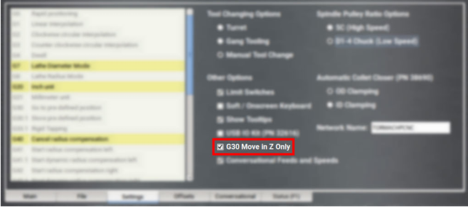
About G30
A G30 command in a G-code program moves the machine to a preset position. For more information on setting a G30 position, see "Use a G30 Position".
Use a G30 move to start a coordinated movement of the axes. You can limit the movement to only the Z-axis. For information, see "Limit G30 Moves".
Tip! It's useful to program a G30 move right before a tool change so that the machine can jog to a safe tool change position.
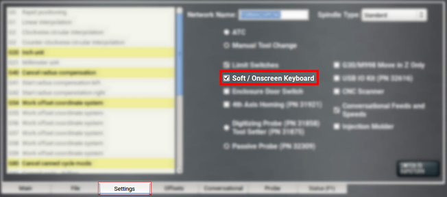
Enable the On-Screen Keyboard
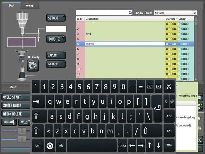
If you have an (optional) Touch Screen Kit (PN 35575), you can use a soft keyboard to type information in the PathPilot interface. For information, see "About Soft Keyboards".
To enable and use the soft (on-screen) keyboard:
-
From the Settings tab, select Soft / On-Screen Keyboard.
-
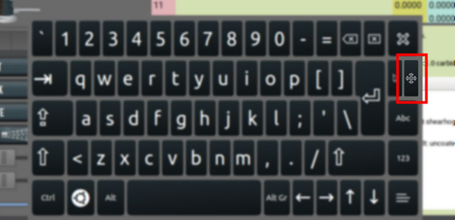
To resize the keyboard, select a corner of the keyboard and drag.
-
To reposition the keyboard, select the Anchor key and drag the keyboard anywhere on the screen.
-
To close the keyboard, select the X key.
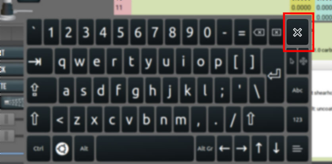
About Soft Keyboards
If you enabled a soft keyboard (on-screen keyboard) in the PathPilot interface to use with an optional touch screen or operator console, a keyboard opens when you select any field where keyboard input is required.
The keyboard displays a wide range of keys: both uppercase and lowercase, symbols, arrow keys, caps lock, backspace and delete, and more.
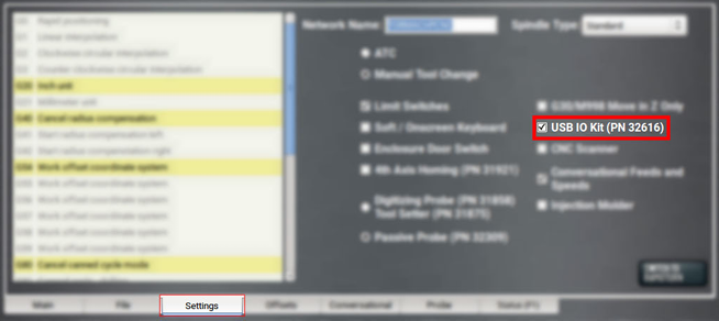
Enable the USB M-Code I/O Interface Kit
If you have a USB M-Code I/O Interface Kit (PN 32616), you must first enable it in the PathPilot interface.
To enable the USB M-Code I/O Interface Kit:
-
From the Settings tab, select USB IO Kit (PN 32616).
Enable Tooltips
PathPilot displays expandable tooltips for many areas of the interface. Hovering over an item, like a DRO field or a button, displays helpful information about the item.
To enable or disable tooltips:
-
From the Settings tab, select or clear Show Tooltips.
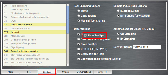
NOTE: If you disable the tooltips, you can still display them for specific items. Hover over an area of the interface, and select the Shift key on the keyboard.
Enable Feeds and Speeds Suggestions in Conversational Routines
You can use PathPilot to automatically calculate feeds and speeds. For more information, see "Use Feeds and Speeds Suggestions".
-
From the Settings tab, select Conversational Feeds and Speeds.

Use a USB Camera
After plugging in the USB camera, navigate to the camera settings. From the PathPilot interface, in the Settings tab, open the Camera(s) tab. Identify the Camera Status read-only dialog box.
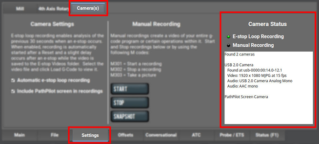
As cameras are plugged in and unplugged, the Camera Status area is refreshed. To test compatibility of any USB camera, plug it in and watch the Camera Status area for the camera name and details.
NOTE: If a camera isn't shown after plugging it in or starting a video recording, it might require too much power from the USB ports on the controller. This is very likely when more than one camera is used. Try using a powered USB hub to add the camera(s).
When a USB camera is plugged in, it's analyzed for supported video and audio formats, frame sizes, and frame rates. If the camera supports it, PathPilot uses H.264 compression; otherwise, it uses Motion JPEG.
If the USB camera has a microphone, PathPilot records audio as well as video. The preferred format is compressed AAC, but uncompressed PCM is used as a fallback.
About USB Cameras
Recording video and audio from USB cameras is supported in PathPilot v2.10.0 and later. You can use up to four cameras simultaneously to record from different vantage points.
NOTE: All cameras are started and stopped at the same time — if you don't want a camera to record, you must unplug it.
USB cameras are compatible with all machine types, but older controllers may lack the processing power and memory needed for camera support. Controllers require 4GB of memory for camera functionality. Use the ADMIN MEMORY MDI command to verify the memory size of a controller.
You can purchase a Tormach USB Camera (PN 51240) with a metal case, mounting bracket, and 15-foot USB cable. Other USB cameras may work (see below), but do not include any technical support.
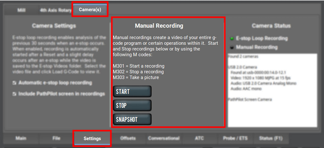
Manual Recording
To start or stop a manual recording, either:
-
Use the controls in the Manual Recording area of the Camera(s) tab.
When a manual recording is stopped, a file save-as dialog appears prompting you for the file name base to use.
-
Select the Video Camera Recording button in the Persistent Controls section.
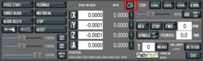
Whenever PathPilot is recording from a USB camera and/or the virtual screen camera, the LED on this button is green. If PathPilot is recording and the button is pressed:
-
If a program is running and not paused at an M00/M01, the recording is aborted.
-
If a program is not running, but the machine is moving, the recording is aborted.
-
Otherwise, if a manual recording is in progress, it is stopped and a file save as dialog will appear. If an automatic e-stop loop recording is in progress, it is aborted since no e-stop occurred.
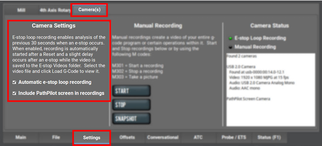
To include a screen recording:
-
Toggle the Include PathPilot screen in recordings checkbox in the Camera Settings area of the Camera(s) tab to enable or disable screen recording.
To take a picture (using all of the USB cameras at once):
-
Select Snapshot in the Manual Recording area of the Camera(s) tab.
The Main tab displays. -
Review the camera images, which display on top of the Tool Path area. The camera images refresh every 0.5 seconds.
-
Align the cameras or adjust lighting to your preference, and then select the Shutter button.
Automatic E-Stop Loop Recording ("Dashcam")
E-stop loop recording enables analysis of the previous 30 seconds after an E-stop. When enabled, recording is automatically started after reset.
To enable or disable the recording of emergency stops:
-
Toggle the Automatic e-stop loop recording checkbox in the Camera Settings area of the Camera(s) tab.
NOTE: This feature is enabled by default.
Automatic E-stop loop recording starts when the Reset button is selected. If you selected Video Camera Recording to abort a previous E-stop loop recording, select Reset to start it again.
To view E-stop videos:
-
A slight delay occurs after an E-stop while the video is saved to the E-stop Videos folder. Select the video file, and then select Load G-Code to view it.
NOTE: The E-Stop Videos folder is automatically monitored for internal drive space use. If the folder size grows beyond 5 GB, the oldest video files are automatically deleted until the folder size becomes less than 5 GB.
Review Video and Image Files
-
On the File tab, select the video or image file and select Load G-Code.
A video player application starts or the image preview is displayed.
Alternatively, you could transfer the video or image files to a Windows or macOS computer for review.
File Naming Convention
For manual and automatic E-stop recordings, the base file name for the recording has automatically chosen suffixes appended for each camera.
For example, if you stop a manual recording of two cameras, specify “Left Bracket Op1” as the name, and enabled screen recording, you'll see the following files:
|
File Name |
Description of File |
|
Left Bracket Op1_0.mp4 |
Camera 0 mp4 video file |
|
Left Bracket Op1_0.log |
Troubleshooting log for camera 0 |
|
Left Bracket Op1_1.mp4 |
Camera 1 mp4 video file |
|
Left Bracket Op1_1.log |
Troubleshooting log for camera 1 |
|
Left Bracket Op1_PP.mp4 |
PathPilot screen recording mp4 video file |
|
Left Bracket Op1_PP.log |
Troubleshooting log for screen recording |
G-Code Commands
PathPilot supports three new M-codes to control cameras within G-code programs: M301, M302, and M303. Example use cases:
-
Record only across each M01 stop where the operator needs to flip a workpiece or change a tool.
-
Create short videos that focus on unique aspects of the program to reduce later video editing.
-
Record USB IO integration operations with robots or other devices (pneumatic vises, etc.).
-
Monitor progress on a workpiece by including M303 throughout the program.
File Naming Conventions
Recordings or pictures created by M301/M302/M303 have automatically generated file names, with the base file name taken from the running G-code file. Video files are saved alongside the G-code file. The suffix for each file uses a time stamp format. This makes it easy to distinguish multiple runs of the same G-code program.
For example, if engrave.nc is running and uses M301 and M302 to create one recording on a machine with one camera, and screen recording is enabled, you'll see the following files:
|
File Name |
Description of File |
|
engrave_2023-02-21_16_58_33_0.mp4 |
Camera 0 mp4 video file |
|
engrave_2023-02-21_16_58_33_0.log |
Troubleshooting log for camera 0 |
|
engrave_2023-02-21_16_58_33_PP.mp4 |
PathPilot screen recording mp4 video file |
|
engrave_2023-02-21_16_58_33_PP.log |
Troubleshooting log for screen recording |
|
engrave_2023-02-21_17_43_22.jpg |
Picture taken by a single M303 later in the program |
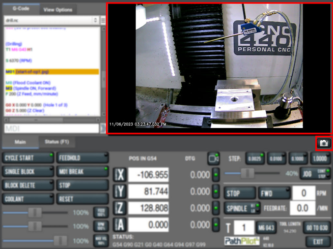
Use M01 to Take Pictures
In addition to displaying information like pictures or messages during an M01 break, you can also use a USB camera (if installed) to take a picture.
To use M01 to take pictures:
-
Add M01 (op1_setup.jpg) into your G-code program.
-
Run the G-code program.
-
When PathPilot executes the M01 it looks to see if the comment contains a file name.
-
If there isn't a file name: The comment is shown as instructional text across the tool path.
-
If there is a file name, but the file doesn’t exist yet and the extension is .jpg, .png, or .jpeg: The USB cameras are initialized and shown in the tool path display.
-
-
Select the Shutter button to take the picture and create the op1_setup.jpg file.
In future runs of the G-code program, op1_setup.jpg will display to the operator for instructional purposes on the workpiece.
For more information, see Display Information and Capture Images During an M00 or M01 Break.
Set Up G-Code Programs
Before running a G-code program, you must first make sure that the machine is properly set up for the specific G-code program.
Set Tool Geometry Offsets
Before running a G-code program, PathPilot must know the geometry of the tools that are required for the program. For more information on using tool length offsets, see "About Tool Offsets".
NOTE: You can import a .csv file with tool geometry offset data. For information, see "Import and Export the Tool Table".
To set tool geometry offsets:
-
Verify that the machine is powered on, out of reset, and the axes have been referenced.
-
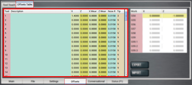
From the PathPilot controller, on the Offsets tab, select the Offsets Table tab.
-
Find the Tool Table window.
-
Touch off the tool geometry offsets. For information, see "Touch Off the Tool Geometry Offsets".
-
(Optional) Select a field to edit. When finished, select the Enter key.
Touch Off the Tool Geometry Offsets
On the Offsets tab, you can use the Tool Touch tab to graphically select a tool, and then touch off the tool to set the geometry offsets.
Tip! When using this method to measure your tool geometry, remember that the X zero location never changes (the spindle centerline is always X = 0), but the Z zero location may change depending on the length of the workpiece that is chucked into the spindle. As long as each tool is measured to a face that has been zeroed, only measure these tools one time or until you replace an insert.
To touch off the tool geometry offsets:
-
From the Offsets tab, on the Tool Touch tab, select a tool.
The tools along the bottom of the screen are front tool post tools (used by machines with a quick-change tool post setup).
NOTE: Gang tooling setups typically use both front and rear tool post tools.
After you select the tool, PathPilot:
-
Sets the tip orientation for the tool, used (along with tip radius) in cutter compensation.
-
Sets the tool type (front tool post or rear tool post), used by the conversational routines to double check the user entry fields in an attempt to try to detect and prevent crashes.
-
Displays the tool touch off dialog.
Touch X
-
Take a skim cut off of the diameter of the workpiece — just long enough to measure the cut surface with a micrometer.
-
Jog the tool away from workpiece in Z, but don't jog the machine in X.
-
Measure the diameter of the skim-cut workpiece with a micrometer.
-
In the Touch X DRO field, type the value that you measured in Step 3.
NOTE: If you're touching off a front tool post tool, verify that the value you enter is positive.
-
Select Touch X.
The LED comes on.
Touch Z
-
Jog the machine toward the part zero (usually the face of the workpiece) in the Z direction.
-
Move the tool so that its cutting edge is just touching the surface of the material and define this as Z = 0. Use a sheet of paper to indicate when the tool is touching the material.
-
Slowly jog the Z-axis until it's approximately 1/4 in. away from part zero on the workpiece.
-
With the paper between the tool and the workpiece, slowly jog the machine until you feel a light pull on the paper.
-
In the Touch Z DRO field, type the thickness of the piece of paper. Then select Touch Z.
About Tool Offsets
Tool offsets allow you to use various tools while still programming with respect to the workpiece. Tools can have different lengths (and, while using gang tooling, different X/Z positions on the carriage).
Tool offsets are broken down into two components:
-
Geometry Offsets Represents the distance from the work offset zero location to the tool’s control point.
NOTE: Unlike on a mill (where G43 must be called out to apply an offset), tool geometry offsets are automatically applied with the Txx tool change command.
-
Wear Offsets
The sign convention for the machine are as follows:
-
Z negative is toward the spindle.
-
X positive is toward the operator.
Sign convention is important when you choose the manual tool change option or the gang tooling option.
All tools mounted for use on the operator side of the workpiece are touched off using positive X (diameter) values, and most X words in part programming for these tools have positive values.
Set Work Offsets
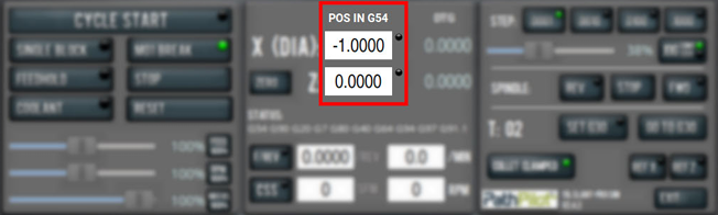
In the the X (Dia) DRO field, all values are expressed in terms of the diameter of the workpiece, not the radius.
Example
If the active tool is 2 in. away from the spindle centerline, 4.000 displays in the X DRO field.
To set the current axis location to zero in the active work coordinate system:
-
Select Zero.
To change work offsets:
-
On the Main tab, in the MDI Line DRO field, type the new work offset to activate (for example, G55). Then select the Enter key.
-
The new work offset displays in the following locations in the PathPilot interface:
-
The Status read-only DRO field.
-
Above the Work Offset DRO fields.
-
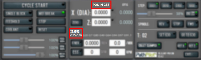
NOTE: The values in the Work Offset DRO fields update to indicate the new location of each axis in the new work offset.
For more information on using work offsets, see "About Work Offsets".
About Work Offsets
Work offsets allow you to think in terms of X and Z coordinates with respect to the part, rather than thinking of them with respect to the machine position. This means that you can jog the machine to an arbitrary location (like the end of a workpiece) and call that location zero.
You can save up to 500 work offsets in PathPilot. The naming structure varies based on the offset number, as detailed in the following table.
|
Work Offset Naming |
||
|
Offsets 1-9 (Use either name) |
||
|
Offset |
Extended Name |
Name |
|
1 |
G54.1 P1 |
G54 |
|
2 |
G54.1 P2 |
G55 |
|
3 |
G54.1 P3 |
G56 |
|
4 |
G54.1 P4 |
G57 |
|
5 |
G54.1 P5 |
G58 |
|
6 |
G54.1 P6 |
G59 |
|
7 |
G54.1 P7 |
G59.1 |
|
8 |
G54.1 P8 |
G59.2 |
|
9 |
G54.1 P9 |
G59.3 |
|
Offsets 10-500 (Use extended name) |
||
|
Offset |
Extended Name |
Name |
|
10 |
G54.1 P10 |
Not used |
|
11 |
G54.1 P11 |
Not used |
|
... |
||
|
499 |
G54.1 P499 |
Not used |
|
500 |
G54.1 P500 |
Not used |
View Work Offsets
To view the current work offset:
-
From the Offsets tab, on the Offsets Table tab, identify the Work Offsets Table window.
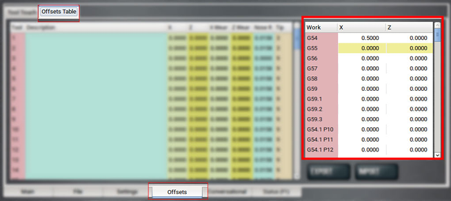
The active work offset is highlighted.
To change the current work offset, go to "Set Work Offsets".
View Available G-Code Modes
The G-Code Description window shows a list of all available G-code modes.
To view available G-code modes:
-
From the Settings tab, find the G-Code Description window.
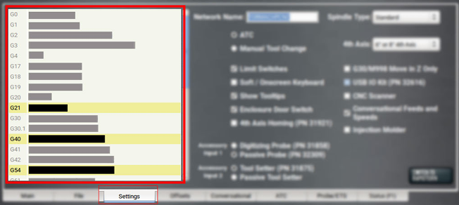
Run G-Code Programs
While running a G-code program, use the following controls:
Bring the Machine Out of Reset
-
Select Reset.
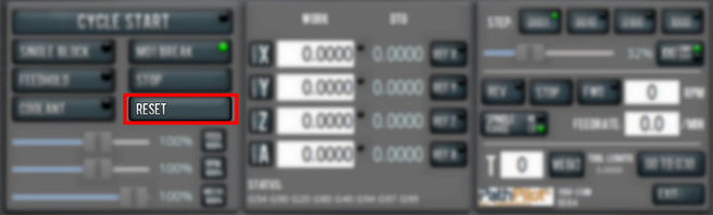
For more information on reset mode, see "About Reset Mode".
About Reset Mode
When the machine is first powered on, or after an emergency stop, the Reset button flashes. When you select the flashing Reset button, PathPilot verifies communication to the machine and does the following activities:
-
Brings the machine out of an emergency stop condition
-
Clears alarms
-
Clears the tool path backplot
-
Resets all modal G-codes to their normal state
-
Rewinds the currently loaded G-code program
-
Stops machine motion, but is not a replacement for the Emergency Stop button
You can select the Reset button any time while the machine is on.
View the Active Axis to Jog
To find which axis is active while jogging your machine:
-
Identify the light next to the Work Offset DRO fields.
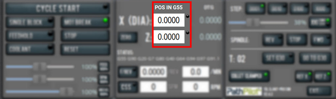
For information, see "Jog the Machine".
Jog the Machine
To switch between jogging modes:
-
From the Manual Control area, in the Jog group, select Jog.
PathPilot toggles between continuous velocity mode and step mode.
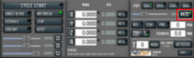
When the Cont green light is on, continuous velocity mode is selected.
When the Step green light is on, step mode is selected.
To use continuous velocity mode:
-
Set the velocity: drag the Jog Speed slider.
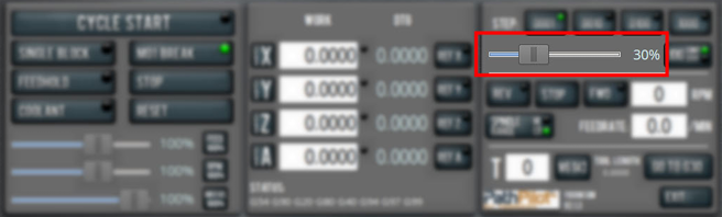
For more information on continuous velocity mode, see "About Continuous Velocity Jogging".
To use step mode, select the step size. Do one of the following, depending on your accessories:
-
In the Manual Control Area, in the Jog group, select the step size.
The Step button's light comes on, indicating which step size is active.
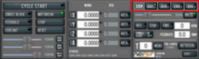
-
On the (optional) Jog Shuttle, press the Step button to toggle the currently selected step size.
In the PathPilot interface, the Step button's light comes on, indicating which step size is active.
For more information on step mode, see "About Step Jogging".
Jog in Continuous Velocity Mode
In continuous mode, the machine jogs at a continuous velocity.
To select continuous velocity mode:
-
In the Manual Control area, select Jog.
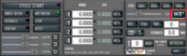
When the Cont green light is on, continuous velocity mode is selected.
When the Step green light is on, step mode is selected.
To set the velocity:
-
Drag the Jog Speed slider.

About Continuous Velocity Jogging
While jogging in continuous velocity mode, the machine moves at a constant speed for as long as:
-
A keyboard key is pressed
-
The Jog Shuttle outer ring is twisted away from the neutral position
This is useful when you're doing things like:
-
Roughly positioning the machine (for example, to move the spindle head away from the workpiece).
-
Moving the machine a certain distance at a constant speed.
Jog in Step Mode
In step mode, the machine jogs in steps, which range based on the programming mode you're using:
-
Imperial (G20) Mode 0.0001 in. to 0.1000 in.
-
Metric (G21) Mode 0.01 mm to 10 mm
To select the step size:
-
In the Manual Control Area, select the step size.
The Step button's light comes on, indicating which step size is active.
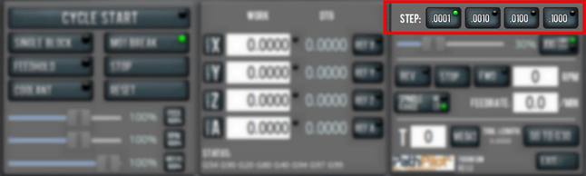
About Step Jogging
While jogging in step mode, the machine moves one step each time you either press a jog key on the keyboard or click the inner wheel of the Jog Shuttle. The jog step sizes range depending on the programming mode you are using:
-
Imperial (G20) Mode 0.0001 in. to 0.1000 in.
-
Metric (G21) Mode 0.01 mm to 10 mm
Step jogging mode is useful to finely move the machine, like when you're indicating a workpiece or manually setting tool lengths.
The jog keys on the keyboard only move the machine in steps when step mode is indicated in PathPilot. The inner wheel on the jog shuttle always moves the machine in steps, regardless of which mode is indicated in PathPilot.
View the Current Machine Position
-
Identify the Work Offset DRO fields.
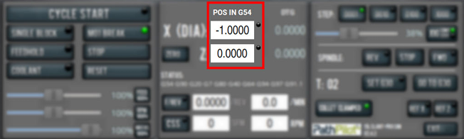
The position is expressed by the currently active work offset coordinate system (like G54 or G55).
When the machine isn't moving, you can edit the DRO fields. For more information on setting work offsets, go to "Set Work Offsets".
Reference the Machine
-
Verify that the machine can freely move to its reference position (at the ends of travel).
-
To verify that the tooling is clear of any possible obstructions, reference the Z-axis before referencing the other axes: from the PathPilot interface, select Ref Z.
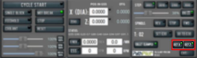
-
Once the spindle is clear of any possible obstructions, continue referencing all axes.
NOTE: You can select the buttons one after another. Once the machine references one axis, it'll move on to the next.
After each axis is referenced, its button light comes on.
For more information on referencing the machine, see "About Referencing".
About Referencing
You must reference the machine to establish a known position for PathPilot. The position that's set while referencing the machine is the origin of the machine coordinate system. Without referencing the machine, PathPilot won't know the current position of the machine axes.
You must reference the machine at the following times:
-
After you power on the machine
-
After you push in the Emergency Stop button
-
Before running a G-code program
-
Before using MDI commands
-
Before setting work or tool offsets
-
After a collision or an axis stall/fault
When referencing, the machine moves each axis to the end of its travel. The machine stops at the limit switch, which sets the axis’ reference position.
Start a Program
-
From the PathPilot interface, in the Main tab, select Cycle Start.
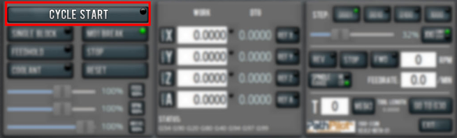
For more information on starting a program, see "About Cycle Start".
If you can't start a program, go to "Cycle Start Reference".
About Cycle Start
While a program is running, the Cycle Start button's light is on. Selecting Cycle Start causes an alarm unless the chuck guard or enclosure door is closed and a valid G-code program is loaded.
The Cycle Start button's light flashes if motion is paused during the program. The following modes may pause motion during a program:
-
Single block
-
Feed hold
-
M01 break
If machine motion pauses a single block, feed hold, or M01 break, the Cycle Start button flashes until it's selected again.
Cycle Start Reference
The Cycle Start button doesn't operate if you select it:
-
While you're not in the Main tab. For information, see “Main Tab” Reference.
-
Before you've loaded a G-code program. For information, see "Load G-Code".
-
Before referencing the machine. For information, see "Reference the Machine"
Stop Machine Motion
-
From the Program Control area, select Stop.
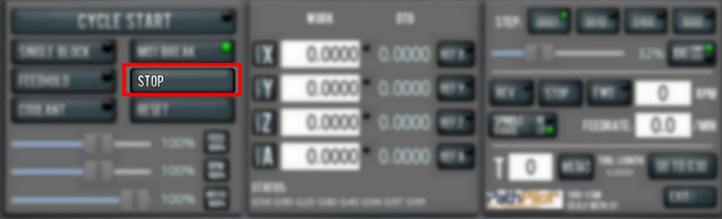
Operate the Coolant Pump
To turn coolant on or off:
-
Select Coolant.
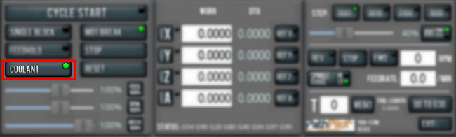
For more information on turning on and off coolant, see "About Coolant".
About Coolant
In the PathPilot interface, the Coolant button controls the machine's coolant pump power outlet. The Coolant button’s light shows the current state of the outlet: the light is on when the outlet has power; the light is off when the outlet does not have power.
NOTE: The Coolant button is equivalent to using an M08 (coolant on) or M09 (coolant off) command in the G-code program.
Use the Coolant button before or after a program is running, while a program is running, or while you are using manual data input (MDI) commands.
View the Active G-Code Modes
To find the currently active G-code modes and the currently active tool at a glance:
-
Identify the Status read-only DRO field.
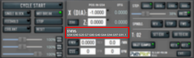
For more information on G-code modes, go to "View Available G-Code Modes".
View the Distance to Go
To view the distance to go:
-
Identify the DTG read-only DRO fields.
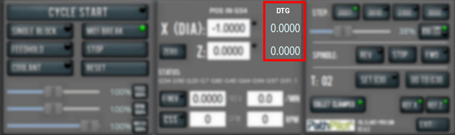
The value is the remaining distance in any programmed move.
For more information on using the DTG read-only DRO fields, see "About Distance to Go".
About Distance to Go
While a program is running, the DTG read-only DRO fields show the remaining distance in each move.
After using the feed hold function or the maxvel override function, look at the distance to go. This read-only DRO field is useful to prove out a part program.
Control G-Code Programs
If necessary, use the following controls to add to your G-code program:
Use the Feed Hold Function
-
Select Feed Hold.
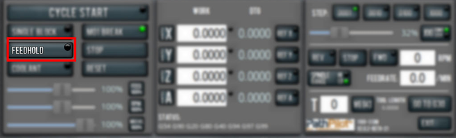
Tip! Use the Spacebar key to quickly activate the feed hold function.
For more information on using the feed hold function, see "About Feed Hold".
About Feed Hold
When the feed hold function is active, the Feed Hold button's light is on.
The feed hold function pauses machine motion — aside from the spindle — and the Cycle Start button flashes. For information, see "About Cycle Start".
NOTE: If the machine isn't moving, the feed hold function doesn't have an effect.
You can use the feed hold function either while a program is running or while you are using manual data input (MDI) commands. If the program is running a spindle-synchronized move, the feed hold function is delayed until the move is complete.
Use the Feed Rate Override Function
To use the feed rate override function:
-
Using the Feed Rate Override slider, change the programmed feed rate by a specific percentage.
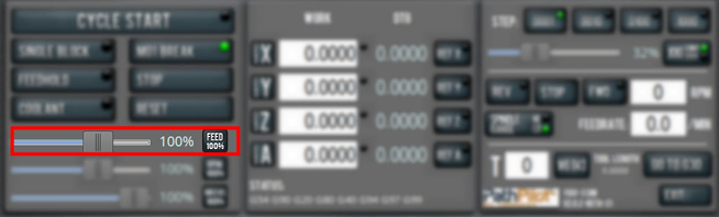
NOTE: Percentages range from 1-200%.
To remove the feed rate override function:
-
Select Feed 100%.
The feed rate returns to 100% of its programmed value (it's no longer overriden).
For more information on the feed rate override function, see "About Feed Rate Override".
About Feed Rate Override
You can use the feed rate override function while you're doing any of the following activities:
-
Using manual data input (MDI) commands
-
Jogging
-
Running a program with G01, G02, or G03 commands
The feed rate override function does not affect G00 (rapid) commands. It's ignored if:
-
The program is running a spindle-synchronized move
-
An M48 (disable feed and speed overrides) command is used
To indicate lack of motion or unusual levels, the slider turns yellow when it's either at 0% or above 100%.
The Feed Rate Override slider and Feed 100% button work similarly to the spindle override controls. They affect the commanded feed rate by a percentage from 1-200%. The feed rate override works for MDI, jogging, and G-code program G01/G02/G03 moves. The override has no effect on G00 (rapid) moves.
Use M01 Break Mode
-
Select M01 Break.
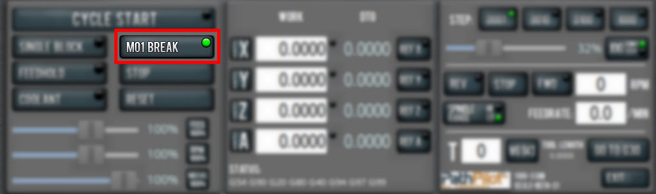
For more information on using M01 break mode, see "About M01 Break".
About M01 Break
When the M01 break mode is active, the M01 Break button's light is on. When the M01 break mode is inactive, the M01 Break button's light is off.
M01 break mode enables any M01 (optional stop) commands that are programmed in the G-code file. You can turn M01 break mode on or off either before starting a program or while a program is running.
-
When M01 Break is Active Machine motion stops after PathPilot reaches an M01 command, and the Cycle Start button flashes. For information, see "About Cycle Start".
-
When M01 Break is Inactive PathPilot ignores all programmed M01 commands.
Use the Maxvel Override Function
To use the maxvel override function:
-
Using the Maxvel Override slider, change the maximum velocity by a specified percentage.
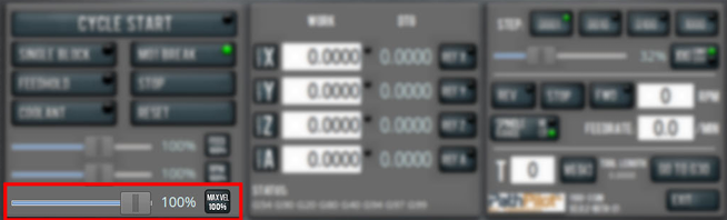
To remove the maxvel override function:
-
Select Maxvel 100%.
For more information on using the maxvel override function, see "About Maxvel Override".
About Maxvel Override
The maxvel override function affects G00 and G01 commands, and it's useful for:
-
Running a Program for the First Time Drag the Maxvel Override slider to 0% to verify that all DRO fields look appropriate.
-
Safety If you're running a spindle-synchronized move, a maxvel override isn't ignored.
Verify that the maxvel override value allows the machine to use the programmed feed rate during spindle-synchronized moves. If it can't, the spindle-synchronized move won't produce the results you want.
To indicate lack of motion or unusual levels, the slider turns yellow when it's either at 0% or above 100%.
Use Single Block Mode
-
Select Single Block.
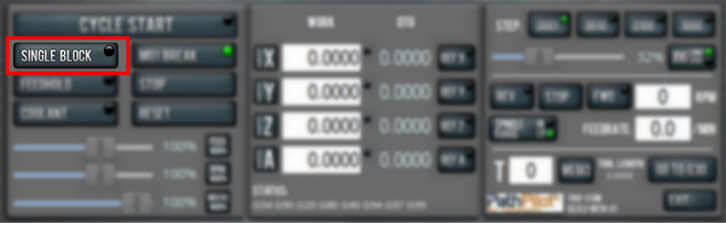
For more information on using single block mode, see "About Single Block".
About Single Block
While single block mode is active, the Single Block button's light is on.
Single block mode runs one line of G-code at a time. After each line, motion is paused, and the Cycle Start button flashes. For information, see "About Cycle Start".
You can turn single block mode on or off either before starting a program or while a program is running. For information, see "Use Single Block Mode".
NOTE: Single block mode ignores non-motion lines, like comment lines or blank lines.
Use the Spindle Override Function
To use the spindle override function:
-
Using the Spindle Override slider, change the programmed spindle speed by a specific percentage.
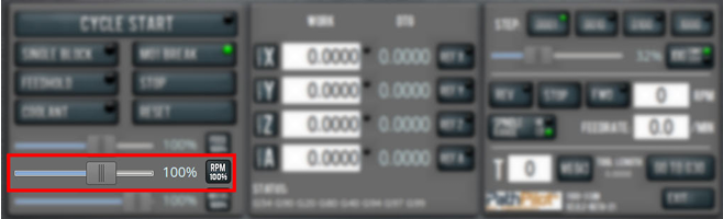
NOTE: Percentages range from 1-200%.
To remove the spindle override function:
-
Select RPM 100%.
The spindle speed returns to 100% of its programmed value (it's no longer overriden).
For more information on using the spindle override function, see "About Spindle Override".
About Spindle Override
The spindle override function won't command the spindle to move past the maximum allowable speed. If the spindle isn't moving, the spindle override function is delayed until the next time spindle starts. The override doesn’t drive the spindle past its maximum speed. It does affect the speed of a spindle command limited by a D word.
You can use the spindle override function while you're doing any of the following activities:
-
Running a program
-
Using manual data input (MDI) commands
The spindle override function is ignored in the following situations:
-
If the program is running a spindle-synchronized move
-
If an M48 (disable feed and speed overrides) command is used
To indicate lack of motion or unusual levels, the slider turns yellow when it's either at 0% or above 100%.
Change the Feed Rate
-
In the Feed Rate DRO field, type in a feed rate. Then select the Enter key.
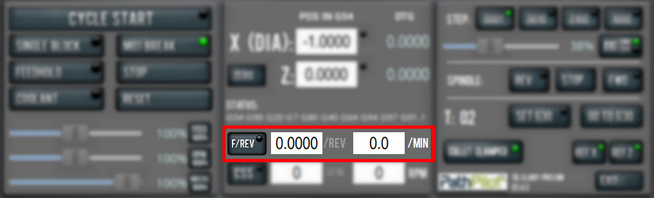
For information, see "About Feed Rates".
About Feed Rates
There are two feed rate modes:
-
Units per Minute (G94) A G-code F word is interpreted to mean the controlled point should move at a certain number of inches or millimeters per minute, depending upon what length units are being used and which axis or axes are moving.
-
Units per Revolution of Spindle (G95) A G-code F word is interpreted to mean the controlled point should move at a certain number of inches or millimeters per spindle revolution depending upon what length units are being used and which axis or axes are moving.
NOTE: We recommend programming in units per revolution for almost all machining done on a lathe.
These settings are mutually exclusive: you cannot simultaneously be in both units per revolution and units per minute modes. The F/Min and F/Rev DRO fields display the current F word in both units/revolution and units/minute. The active mode is indicated in the PathPilot interface: when units per revolution mode is active, the light on the F/Rev button illuminates, the /Rev label (next to the DRO field) is white, and the Min label is gray.
You can turn on units per revolution mode by:
-
Clicking in the F/Rev DRO field, entering a value, and pressing the Enter key on the keyboard.
-
Clicking the F/Rev button.
-
Typing G95 into the MDI Line DRO field, and pressing the Enter key on the keyboard.
-
Running a G-code program with a G95 command.
Change the Spindle Speed
In the Spindle RPM DRO field, type in a spindle speed. Then select the Enter key.
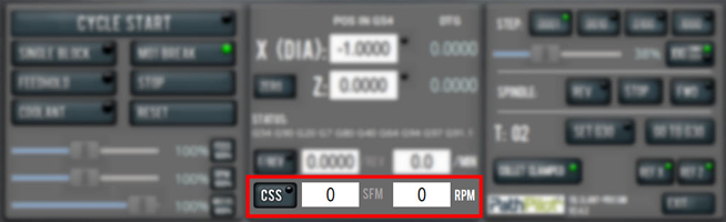
For information, see "About Spindle Controls".
About Spindle Controls
A spindle speed is the rate at which the spindle rotates.
Use the FWD and Stop buttons to manually control the spindle.
|
Button |
G-Code |
Use to... |
|
FWD |
M03 |
Start the spindle clockwise at the RPM specified in the RPM DRO field. |
|
REV |
M04 |
In G97 mode: start the spindle in the reverse direction at the RPM specified in the spindle RPM DRO field. In G96 mode: start the spindle at an RPM specified by the SFM DRO field and the X (Dia.) value in the X DRO field. |
|
Stop |
M05 |
Stop the spindle. |
The FWD and REV buttons and the RPM DRO field don't operate if they're selected when:
-
A G-code program is running.
-
Using manual data input (MDI) commands.
There are two spindle speed command modes:
-
Constant RPM (G97) The spindle turns at an rpm equal to the S word.
Example
G97 S500 M03 starts the spindle at 500 rpm.
-
Constant Surface Speed (G96) The spindle rpm varies to maintain a constant speed in terms of linear feet per minute over the workpiece. The actual spindle RPM depends on the diameter of the work being turned, increasing as diameters get smaller and decreasing as diameters get larger.
Example
G96 S50 M03 turns the spindle on, and the linear speed at which the cutting tool’s control point travels over the work piece’s surface is 50 feet per minute.
NOTE: Because tool life and efficiency depends on surface speed (and not rpm), we recommend constant surface speed mode for all machining on a lathe.
Change the Feed Rate Mode
To turn on F/Rev mode, do any of the following:
-
Select the F/Rev DRO field and enter a value. Then select the Enter key.
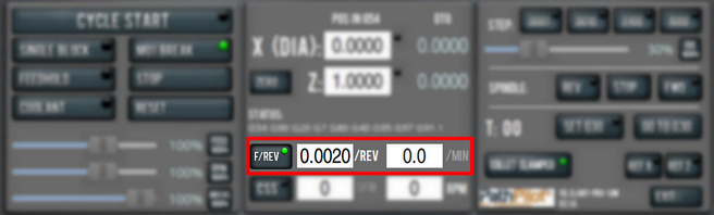
The button's light turns on, and the F/Min DRO field's label turns gray.
-
Select F/Rev when its light is off.
-
Select the MDI Line DRO field and type G95. Then select the Enter key.
-
Run a G-code program that has a G95 command.
You can turn off F/Rev mode by doing any of the following:
-
Select the F/Min DRO field and enter a value. Then select the Enter key.
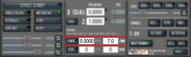
The F/Rev button's light turns off, and the F/Rev DRO field's label turns gray.
-
Select F/Rev when its light is off.
-
Select the MDI Line DRO field and type G94. Then select the Enter key.
-
Run a G-code program that has a G94 command.
For more information on feed rate modes, see "About Feed Rate Modes".
About Feed Rate Modes
The machine recognizes two feed rate modes: units per minute (F/Min) or units per revolution (F/Rev). These settings are mutually exclusive — you can't simultaneously be in both F/Rev and F/Min modes. The F/Min and F/Rev DRO fields display the current F word in both units per revolution and units per minute, with the active mode indicated by both the F/Rev button's light and the DRO fields' labels. For example, when F/Rev is active, the F/Rev button light is on, the F/Rev label is white, and the F/Min label is gray.
Units per Minute Mode (G94)
In units per minute feed rate mode, a G-code F word is interpreted to mean the controlled point should move at a certain number of inches or millimeters per minute, depending upon what length units are being used and which axis or axes are moving.
Units per Revolution Mode (G95)
In units per revolution feed rate mode, an F word is interpreted to mean the controlled point should move at a certain number of inches or millimeters per spindle revolution depending upon what length units are being used and which axis or axes are moving.
NOTE: For almost all machining on a lathe, programming in units per revolution is more desirable.
Change the Spindle Speed Command Mode
To turn on constant surface speed mode (G96):
-
Select the SFM DRO field and enter a value. Then select the Enter key.
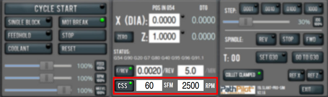
To turn on constant RPM mode (G97):
-
Select the RPM DRO field and enter a value. Then select the Enter key.
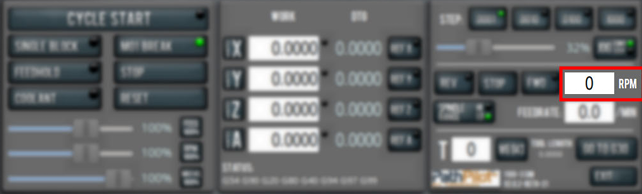
For more information on spindle speed command modes, see "About Spindle Speed Command Modes".
About Spindle Speed Command Modes
The machine recognizes two spindle speed command modes: constant RPM (G97) and constant surface speed (G96).
Constant Surface Speed Mode (G96)
In constant surface speed mode (G96), the spindle RPM varies to maintain a constant speed in terms of linear feet per minute over the workpiece.
Example
G96 S50 M03 turns the spindle on, and the linear speed at which the cutting tool’s control point travels over the work piece’s surface is 50 feet per minute.
In constant surface speed mode, the actual spindle RPM depends on the diameter of the work being turned: it increases as diameters get smaller, and decreases as diameters get larger.
Tip! Because tool life and efficiency depends on surface speed (and not RPMs), we recommend operating in constant surface speed mode.
Constant RPM Mode (G97)
In constant RPM mode (G97), the spindle turns at an RPM equal to the S word.
Example
G97 S500 M03 starts the spindle at 500 RPMs
Change the Tool Number
The Tool DRO field shows the tool currently in the spindle.
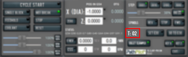
To change the tool number (and apply its tool length offset):
-
From the PathPilot interface, on the Offsets tab, select the Tool Touch tab.
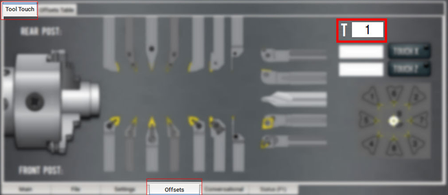
-
In the Tool DRO field, type a number (the valid range is from 0-99). Then select the Enter key.
Use a G30 Position
The Go to G30 button moves the machine to a predefined G30 position. For information, see "About G30".
To set a G30 position:
-
Jog the machine to the desired G30 position.
-
From the Main tab, select Set G30.
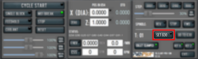
To go to a set G30 position:
-
Do one of the following:
-
Use a G30 command in a G-code program.
-
Select Go To G30.
-
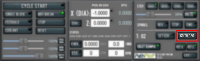
NOTE: The G30 position defaults to only moving the Z-axis.
About G30
A G30 command in a G-code program moves the machine to a preset position. For more information on setting a G30 position, see "Use a G30 Position".
Use a G30 move to start a coordinated movement of the axes. You can limit the movement to only the Z-axis. For information, see "Limit G30 Moves".
Tip! It's useful to program a G30 move right before a tool change so that the machine can jog to a safe tool change position.
Manually Enter Commands
You can send G-code commands directly to the machine by using the MDI Line DRO field. For information, see "About the MDI Line DRO Field".
To manually enter commands:
-
Select the MDI Line DRO field.
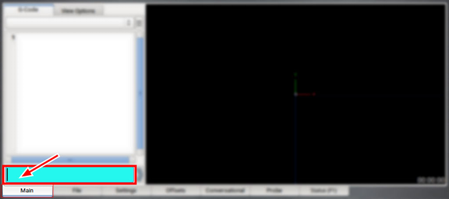
The DRO field highlights.
2. Type the command.
NOTE: You can use the Backspace, Delete, Left Arrow, and Right Arrow keys to correct typing errors.
-
You must press the Enter key to execute the command. To abandon the command, press Esc.
About the MDI Line DRO Field
The MDI Line DRO field allows you to send commands (or, manual data input) directly to PathPilot. For information, see "Manually Enter Commands".
The MDI Line DRO field saves up to 100 of your most recent commands, which are saved after a power cycle.
When you select the MDI Line DRO field, all keystrokes are used within the field — so, you can't jog the machine.
Admin Commands Reference
Use the following commands in PathPilot:
|
Admin Command |
Use to... |
|
Admin Audio |
Customize the controller's audio device settings. |
|
Admin Calc |
Open the calculator. |
|
Admin Clear |
Clear the message history on the Status tab. |
|
Admin Config |
Change the configuration of the PathPilot interface. |
|
Admin CycleCounter |
Control the cycle counters in the Tool Path display. |
|
Admin Date |
Customize the controller's date and time. |
|
Admin Display |
Customize the controller's screen display. |
|
Admin Dropbox |
Connect your controller to a Dropbox account for cloud file syncing. |
|
Admin Help |
Review a list of available Admin commands. |
|
Admin Keyboard |
Customize the controller's keyboard layout. |
|
Admin Logdata |
Write the latest machine log data to a USB drive for technical support assistance. |
|
Admin Memory |
Determine how much total RAM is on your controller. |
|
Admin Mouse |
Change the mouse preferences, like pointer speed and right- or left-hand button mapping |
|
Admin Network |
Configure a Wi-Fi network. |
|
Admin Reset_Soft_Limits |
Reset axis soft limits to machine defaults. |
|
Admin Set_X_Limit |
Set the X-axis soft limit. |
|
Admin Set_Y_Limit |
Set the Y-axis soft limit. |
|
Admin Set_Z_Limit |
Set the Z-axis soft limit. |
|
Admin Settings Backup |
Create a backup of tool offset and fixture information to store externally. |
|
Admin Settings Restore |
Restore tool offset and fixture information backup from an external location. |
|
Admin Show_Soft_Limits |
Display the current axis soft limits on the Status tab. |
|
ADMIN TOOLTIP DELAYMS |
Set the milliseconds prior to displaying the tooltip (and then again for the expanded tooltip). The default is 1200 milliseconds. |
|
ADMIN TOOLTIP MAXDISPLAYSEC |
Limit the amount of time the expanded tooltip displays. The default is 15 seconds. |
|
Admin Touchscreen |
Adjust the touch screen calibration. |
|
Admin Version |
Display detailed version information on the Status tab. |
Copy Recently Entered Commands
-
From the MDI Line DRO field, press either the Up Arrow key or the Down Arrow key.
The previously entered command displays. -
You must press the Enter key to execute the command. To abandon the command, press Esc.
For information, see "Manually Enter Commands".
Use Feeds and Speeds Suggestions
NOTE: Calculating feeds and speeds requires that PathPilot has relevant details about the tooling. If you haven't yet done so, go to "Create Tool Descriptions".
You can use PathPilot to automatically calculate feeds and speeds: from the Conversational tab, in the Conversational DROs group, select a material, a sub-type, and a tool.
-
If you haven't yet done so, enable the conversational feeds and speeds setting. From the Settings tab, select Conversational Feeds and Speeds.
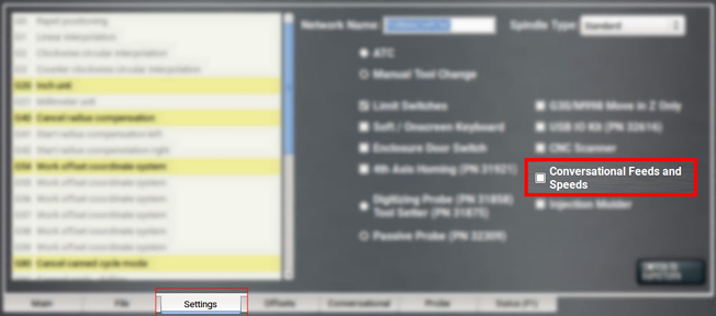
-
From the Conversational tab, locate the Material dropdowns in the Conversational DROs group.
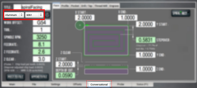
-
From the Material dropdown, select your material (like Aluminum or Plastic).
-
If required, from the Sub-Type dropdown, select the material sub-type (like -any- or 6061).
-
In the Tool DRO field, type the assigned tool number.
-
Select Refresh (to the right of the Sub-Type dropdown).
The following machining-related DRO fields are calculated:
-
Roughing SFM
-
Finishing SFM
-
Max Spindle RPM
-
Roughing (in/rev)
-
Finishing (in/rev)
-
Finishing DOC
-
Roughing DOC
-
Peck (if drilling)
NOTE: After PathPilot calculates values for the machining-related DRO fields, the background turns green.
-
(Optional) You can adjust the values in the calculated DRO fields. Adjusting the value in one of these DRO field doesn't change the value in the other machining-related DRO fields.
NOTE: Once you adjust the value in the DRO field, the background switches from green back to white. This helps you identify which DRO fields have suggested values (those with a green background), and which DRO fields have values you've supplied (white background).
Refresh DRO Field Values
The suggested values are no longer valid if:
-
You select different material or sub-type values, or if you type a new value in to the Tool DRO field.
The suggested feeds and speeds are made by taking into account all of these values. Changing any value requires you to refresh. -
You select a different Conversational tab.
The suggested feeds and speeds are made by taking into account the current, specific conversational operation. Changing your conversational operation requires you to refresh the feeds and speeds values.
When the feeds and speeds are no longer valid, the Refresh button turns green, and the machining-related DRO field backgrounds switch from green to white, as shown in the following image.
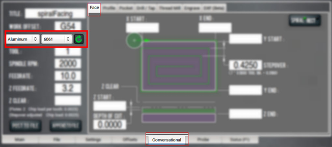
Enable Feeds and Speeds Suggestions in Conversational Routines
You can use PathPilot to automatically calculate feeds and speeds. For more information, see "Use Feeds and Speeds Suggestions".
-
From the Settings tab, select Conversational Feeds and Speeds.
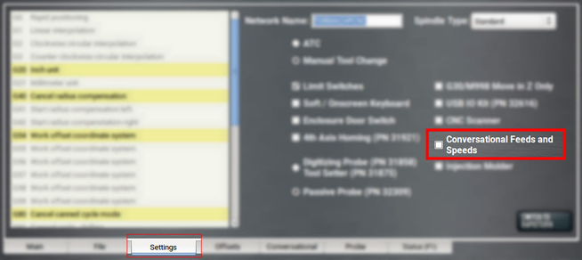
Create Tool Descriptions
If desired, you can create tool descriptions in PathPilot. Detailed tool descriptions allow you to receive feeds and speeds suggestions in conversational programming. For information, see "Use Feeds and Speeds Suggestions".
Manually Enter Tool Descriptions
PathPilot uses keywords and patterns in the tool description to recognize tooling features. For information, see "Tool Keywords Reference".
To manually enter tool descriptions:
-
From the PathPilot interface, on the Offsets tab, select the Offsets Table tab, and identify the Tool Table window.
-
Select a blank line.
-
Type a description for the tool. Descriptions are not case sensitive.
If a pattern or word in the description is recognized, PathPilot uses syntax highlighting to indicate a valid description.
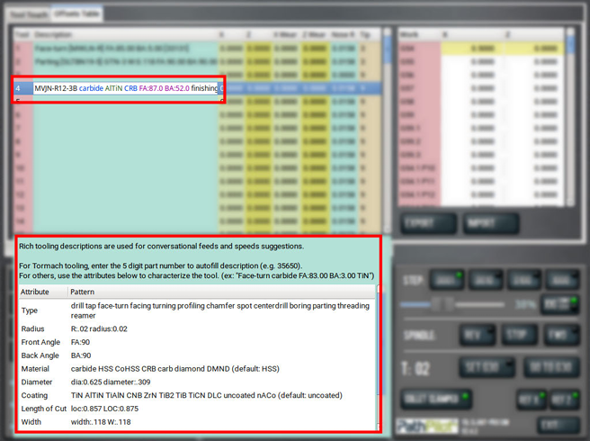
Examples
To get accurate machining information, all tooling must be described with detail: the more detail, the better the results.
Example
MVJN-R12-3B carbide AlTiN CRB FA:87.0 BA:52.0 finishing
This description provides the following to PathPilot to calculate machining information:
-
MVJN holder geometry
-
Aluminum-titanium nitride coated carbide (AlTiN)
-
Carbide
-
87° front angle
-
52° back angle
Using a personal description likely won’t contain meaningful information for PathPilot.
Example
Gold colored tool bit from middle drawer
This description provides very little information, and PathPilot defaults to tool bit features from the setup on the Tool Touch tab.
Automatically Generate Tool Descriptions
If you're using a Tormach tool, you can enter the part number to automatically generate tool descriptions in the Tool Table window.
NOTE: If you don't know the part number, you can search for the tool at tormach.com.
-
From the PathPilot interface, on the Offsets tab, in the Tool Table window, select a blank line.
-
Type the part number for the tool, like 33133.
A full description for a right-handed profiling tool (PN 33133) displays.
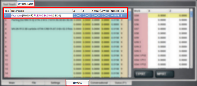
-
You must use the Tool Touch tab to zero the tool for the correct X offset and Y offset.
Tool Keywords Reference
PathPilot uses keywords and patterns in the tool description to recognize tooling features.
|
Item |
Pattern |
Example |
Notes |
|
type |
drill, tap, face-turn, facing, turning, profiling, chamfer, spot, centerdrill, boring, parting, threading, reamer |
Drill, Chamfer, Boring |
|
|
tool radius |
“R” or “radius”, followed by a colon, followed by a decimal number |
R:.0158, radius:0.32 |
No radius specified is the same as a zero radius. |
|
front angle |
“FA”, followed by a colon, followed by a decimal number |
FA:90 |
|
|
back angle |
“BA”, followed by a colon, followed by a decimal number |
BA:90 |
|
|
tool material |
carbide, HSS, CoHSS, CRB, carb, diamond, DMND |
HSS, CoHSS, crb |
HSS: High-speed steel; CoHSS: Cobalt high-speed steel; CRB: Carbide; No tool material specified is the same as HSS. |
|
tool diameter |
“dia” or “diameter”, followed by a colon, followed by a decimal number |
Dia:.0341, diameter:.750 |
For axial tools (drills taps, reamers, etc.). |
|
tool coating |
TiN, AlTiN, TiAlN, CNB, ZrN, TiB2, TiB, TiCN, DLC, uncoated, nACo |
TiN, ZrN, TiB2 |
No coating specified is the same as uncoated. |
|
length of cut |
“loc”, followed by a colon, followed by a decimal number |
loc:0.875 |
For axial tools (drills, reamers, etc.). If no length of cut is specified, a length will be assumed based on cutter diameter. |
|
tool width |
“width” or “w”, followed by a colon, followed by a decimal number |
W:.118, width:.118 |
For grooving and parting tools. |
|
min bore |
“min-bore”, followed by a colon, followed by a decimal number |
min-bore:.522 |
|
|
flutes |
A number, followed by “FL” or “FLUTE” |
4FL, 12FL, 2flute |
No flutes specified is the same as 2 flutes. |
Use Cycle Counters (M30 and M99)
On the Main tab, the Tool Path display shows M30 and M99 cycle counters. They're useful to count parts completed during unattended operation. For each M-code, there's an A and B counter. This provides more flexibility, because you can reset them to 0 independently.
For example, you could use M30 A to count parts each shift, and M30 B to count parts each week. The cycle counters persist across the controller's power cycles.
Monitor Cycle Counters
-
In the MDI Line DRO field, type ADMIN CYCLECOUNTER to show or hide the counters and to reset them to 0.
Change Cycle Counter Values
The cycle counters are implemented as read-only persistent G-code numbered parameters, as detailed in the following table. If needed, the cycle counter value can be read in G-code.
|
Cycle Counter |
Parameter |
|
M30 A |
#5650 |
|
M30 B |
#5651 |
|
M99 A |
#5652 |
|
M99 B |
#5653 |
To change a counter value explicitly, use a G10 command: G10 L99 P~ Q~
-
P~ selects the cycle counter to change. Use any of the values detailed in the following table.
|
Cycle Counter |
P~ |
|
M30 A |
0 |
|
M30 B |
1 |
|
M99 A |
2 |
|
M99 B |
3 |
-
Q~ specifies the value to set the cycle counter. If Q~ is omitted, the cycle counter is incremented by 1.
For example, if you program G10 L99 P2, the M99 A cycle counter increments by 1.
System File Management
To keep the files on your system backed up and organized, use the following controls:
Manage System Files
Use the File tab to manage system files on the PathPilot controller. For information, see "Transfer Files to and From the Controller".
To manage system files:
-
From the PathPilot interface, on the File tab, do any of the following from the Controller Files window:
-
Select a file, and then select New Folder, Rename, or Delete.
-
Select a file, and go to the Options menu. Then, select Copy, Cut, or Paste.
-
To navigate through the system files:
-
Select Back or Home.
Create Backup Files
-
Insert a blank, formatted USB drive into the PathPilot controller.
NOTE: To prevent errors when backing up and restoring files, only use a blank, formatted USB drive. Do not use the PathPilot v2.0 Upgrade.
-
From the PathPilot interface, on the Main tab, in the MDI Line DRO field, type ADMIN SETTINGS BACKUP. Then select the Enter key.
PathPilot generates a backup .zip file, and the Admin Settings Backup dialog box displays.
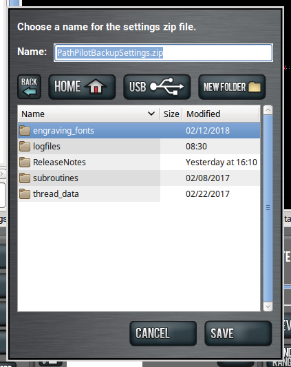
-
From the Admin Settings Backup dialog box, specify where (on the PathPilot controller or on a USB drive) to save the backup .zip file.
-
Select Save.
The backup .zip file is saved in the location you specified in Step 3. -
If you saved the backup .zip file on the PathPilot controller, you must manually transfer it — along with other files you want to back up (like G-code programs) — to a USB drive. From the PathPilot interface, on the File tab, in the Controller Files window, select the backup .zip file and any other files you want to back up.
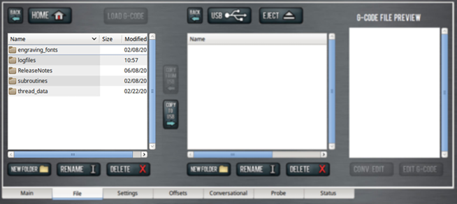
NOTE: Files must have unique names. If they don't, PathPilot prompts you to overwrite or rename files, or cancel the file transfer.
-
To prevent errors, make sure you don't include the following folders:
-
logfiles
-
media
-
ReleaseNotes
-
subroutines
-
USB
-
Select Copy to USB.
The files are copied and display in the USB Files window. -
Eject the USB drive from the PathPilot controller.
-
From the PathPilot interface, select Exit.
-
Verify that all files are properly saved: insert the USB drive on a device other than the PathPilot controller, and review the list of files on the USB drive.
-
(Optional) As an extra precaution, copy all the files onto the device.
-
Go to Install PathPilot v2.x.
About Backup Files
Make a regular backup of all tool offset and fixture information and machine settings stored on your PathPilot controller. Store the file externally to use if you replace your controller or restore it to factory settings.
Restore Backup Files
-
Insert the USB drive with your backup files into the PathPilot controller.
-
From the PathPilot interface, on the Main tab, in the MDI Line DRO field, type ADMIN SETTINGS RESTORE. Then select the Enter key.
The Admin Settings Restore dialog box displays.
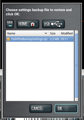
-
From the Admin Settings Restore dialog box, navigate to the backup .zip file on the USB drive, and then select OK.
The PathPilot operating system restores the backup, then restarts. -
If you backed up any other files onto the USB drive, you must manually transfer the files to the PathPilot controller. From the PathPilot interface, on the File tab, in the USB Files window, select the files you want to transfer.
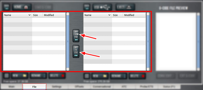
NOTE: To navigate backward, select Back. To navigate to the top level, select USB.
-
From the Controller Files window, select the folder into which you want to copy the files.
-
Select Copy From USB.
The files display in the Controller Files window.
NOTE: Files must have unique names. If they don't, PathPilot prompts you to overwrite or rename files, or cancel the file transfer.
-
If desired, you can enable an Internet connection in the PathPilot controller, which allows you to use PathPilot HUB, and receive automatic PathPilot updates. Go to the next section, "Enable an Internet Connection".
If you don't want to use these features, you have completed installing and configuring PathPilot v2.x.
Import and Export the Tool Table
You can manage the tool table using an external .csv file.
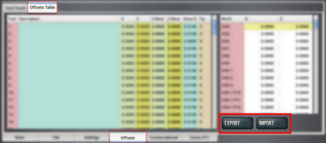
Import a .csv File
-
Transfer the .csv file to a USB drive.
-
Insert the USB drive into the PathPilot controller.
-
Confirm that the PathPilot controller is on.
-
From the Offsets tab, on the Offsets Table tab, select Import.
The Import dialog box displays.
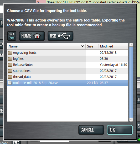
-
Navigate to the .csv file on the USB drive. Then, select OK.
The .csv file updates the tool table.
Export the Tool Table as a .csv File
-
From the Offsets tab, on the Offsets Table tab, select Export.
PathPilot generates the .csv file, and the Export dialog box displays.
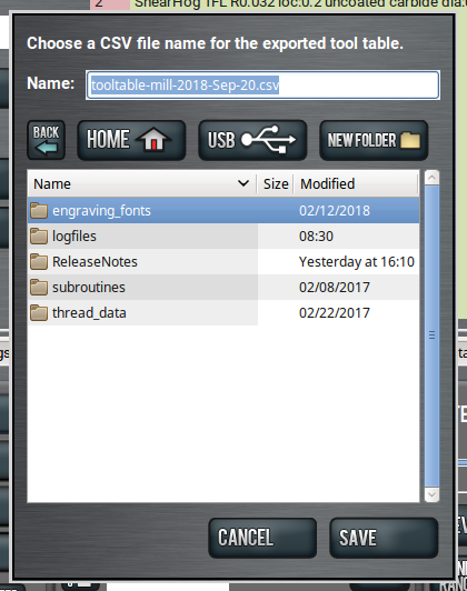
-
In the Name DRO field, type the name for the .csv file.
-
Select Save.
The .csv file is saved in the File tab. -
From the File tab, select the newly created .csv file, and then select Copy to USB.
-
Select Eject.
It's safe to remove the USB drive from the controller.
Looking for more information?
This is a section of the 15L operator's manual. To view the whole manual, go to Tormach document UM10225.
If you have additional questions, we can help. Create a support ticket with Tormach Technical Support at tormach.com/how-to-submit-a-support-ticket for guidance on how to proceed.