In This Section, You'll Learn:
About the languages that are understood and interpreted by PathPilot.
Before You Begin
-
Referring to This Section Use this section only for reference. To learn about the principles of the control language (so that you can write programs by hand from first principles, for example), we recommend that you consult an introductory textbook on G-code programming.
-
Creating and Editing G-Code Files We recommend using a text editor like Gedit or Notepad++. Don't use a word processor to create or edit G-code files — it'll leave unseen codes that could cause problems or prevent a G-code file from working.
Definitions
Read the following sections for reference:
Linear Axes
The X- and Z-axes are at right angles to each other. The Z-axis lies along the centerline of the spindle; distance values increase moving away from the spindle towards the right-hand side of the machine. The X-axis distance values increase as the tool moves up and away from you. The tool cutting position (controlled point) is represented by coordinates on these axes.
Controlled Point
The controlled point is the point whose position and rate of motion are controlled to make cuts. In practice, a tool is not a point – the sharper the point of a tool, the weaker it is – so a tip radius is always part of the tip profile. If this tool is in a front tool post, it can turn to a diameter moving toward the headstock (Z-) and face toward the centerline (X+).
Many standard shapes of tools are available; PathPilot doesn't need to know the exact shape of the tool, but does need to know where it is used to cut and how to interpret the controlled point.
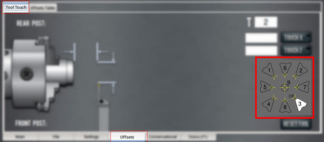
There are nine possible orientations for the cutting point, identified by numbers shown in the following image (with orientation code 3 illustrated). If this tool is put in the turret, or a rear position on the gang plate, it's orientation 2.
-
Tools with orientations 1, 2, 3, and 4 all turn to size and face. Their controlled points are the intersection of tangents to the cutting tip radius so the radius has no effect on the diameter or length of the part made.
If, however, the cut is angled, then the radius means it does not cut the expected part but one a little larger than required.
To machine a part corresponding to the angled tool path defined in the G-code, it is necessary to use tool-tip radius compensation (i.e., G41 or G42). -
Tools with orientations 6 and 8 turn diameters to size and are often used for making profiles. It is difficult to accurately estimate their controlled point in the Z-direction.
-
Tools with orientations 5 and 7 turn on the face of stock and are unusual. It is difficult to accurately estimate their controlled point in the X-direction without a test cut.
-
Tools with orientation 9 are used when tool-tip compensation is applied in all moves.
Some orientations seem unusual at first glance, like a parting or grooving tool in the front tool post has orientation 4. This is because the program defines the part to the right of the tool. The size of the waste left in the chuck is unimportant.
Coordinated Linear Motion
To drive a tool along a specified path, a machining system must often coordinate the motion of both. We use the term coordinated linear motion to describe the situation in which each axis moves at constant speed and both axes move from their starting positions to their end positions at the same time. Because a lathe only has X- and Z-axes, this produces motion in a straight line (linear). In actual motions, it's often not possible to maintain constant speed because acceleration or deceleration is required at the beginning and/or end of the motion. It's feasible, however, to control the axes so that, at all times, each axis has completed the same fraction of its required motion as the other axes. This moves the tool along the same path and we also call this kind of motion coordinated linear motion.
Coordinated linear motion can be performed either at the prevailing feed rate or at rapid traverse rate. If physical limits on axis speed make the desired rate unobtainable, the axes are slowed to maintain the desired path.
Feed Rate
The rate at which the controlled point or the axes move is nominally a steady rate which may be set by you. In the interpreter, the interpretation of the feed rate is as follows unless inverse time feed rate (G93) mode is being used: the feed rate means the length in units per minute or units per spindle revolution along the programmed linear path.
Arc Motion
The axes can be controlled to move in a circular arc in the plane of the axes. While this is occurring, as in coordinated linear motion, the motions can be coordinated so that acceleration and deceleration do not affect the path.
Coolant
Although G-code provides for separate flood and mist coolant, either M07 or M08 turn on the lathe's coolant pump and M09 turns it off.
Dwell
A machining system may be commanded to dwell (keep the axes unmoving) for a specific amount of time. The most common use of dwell is to break and clear chips or for a spindle to get up to speed. The units in which you specify dwell are seconds; a decimal value can be used to get less than one second.
Units
Units used for distances along the X- and Z-axes may be measured in millimeters or inches. Units for all other quantities involved in machine control cannot be changed. Different quantities use different specific units. Spindle speed is measured in revolutions per minute. Feed rates are expressed in current length units per minute.
Current Position
The controlled point is always at some location called the current position, and PathPilot always knows where that is. The numbers representing the current position are adjusted in the absence of any axis motion if any of several events take place:
-
Length units are changed
-
Tool length offsets are changed
-
Work offsets are changed
NOTE: These events do not move the tool, instead they change its displayed position in the axis DROs.
Work Offsets
Work offsets allow you to jog the machine to an arbitrary location (like the end of a workpiece) and call that location zero. Only one work offset can be active at any given time. The default (used in this example) is G54.
Selected Plane
There is always a selected plane, which for a lathe is the XZ-plane of the machining system.
Tool Table
Zero or one tool is assigned to each slot in the tool table. The table defines the offset of the controlled point of the tool from the work offset coordinate system’s origin, the wear corrections to be made to this tool offset, the tool tip radius, and the orientation of the tool tip.
Wear Offsets
Wear offsets are values used to fine tune a part program to compensate for things like tool wear or spring back. Wear offsets are applied with the T command as well, by specifying the desired wear offset register with the last two digits of a four-digit T command. For example, T02 applies the geometry offsets for tool 2, whereas T0202 applies both geometry offsets and wear offsets. Note that either command causes the turret to change position to pocket 2 if the machine is equipped with a turret. There is no M6 tool change command for lathes like there is for CNC milling machines.
Path Control Modes
The lathe may be put into any one of three path control modes:
-
Exact Stop Mode The machine stops briefly at the end of each programmed move.
-
Exact Path Mode The machine follows the programmed path as exactly as possible, slowing or stopping if necessary at sharp corners of the path.
-
Continuous Mode with Optional Tolerance Sharp corners of the path may be rounded slightly so that the feed rate may be kept up (but by no more than the tolerance, if specified).
Feed and Speed Override Controls
PathPilot has commands which enable (M48) or disable (M49) the feed and speed override slider controls. It is useful to be able to override these for some machining operations. Default settings in the program are set and the operator should not change them.
Block Delete Control
PathPilot doesn't implement the optional omission of blocks of code that are prefixed with the forward slash symbol (/).
Optional Program Stop Control
The optional program stop control (M01 Break) works as follows: if the button is selected, and an input line contains an M01 code, program execution is stopped at the end on the commands on that line until you select Cycle Start.
Programming Overview
Read the following sections for a G-code overview:
About G-Code Programming Language
A G-code program is made up of one or more lines of code. Each line of code is called a block, and can include commands to the machine. Blocks are collected into a file, which makes a program.
A block is normally made up of an optional line number at the beginning, followed by one or more words, which groups the elements together into a single statement.
A word is a letter followed by a number (or, something that evaluates to a number). A word can either give a command or provide an argument to a command.
A program is one or more blocks, each separated by a line break. Blocks in a program are executed either:
-
Sequentially (from the top of the program to the bottom)
-
Until an end command (M02 or M30) is encountered
Example:
G01 X3 is a valid line of code with two words:
-
G01 is a command: the machine should move in a straight line at the programmed feed rate.
-
X3 provides an argument value: the value of X should be 3 at the end of the move.
Most commands start with either G (general) or M (miscellaneous) — G-codes and M-codes.
There are two commands (M02 and M30) that end a program. A program can end before the end of a file. If there are lines in a file after the end of a program, they're not meant to be executed in the normal flow (they're generally parts of subroutines).
G-Code Formatting Reference
A permissible block of input code is made up of the following programming elements, in order, with the restriction that there is a maximum of 256 characters allowed on a line:
-
(Optional) Block delete character (/)
-
(Optional) Line number
-
Any number of words, parameter settings, and comments
-
End of line marker (carriage return or line break)
Programs are limited to 999,999 lines of code.
Spaces and tabs are allowed anywhere on a line of code and do not change the meaning of the line, except inside comments. Blank lines are allowed in the input, but they're ignored. Input is not case sensitive (except in comments), so any letter outside a comment may be in uppercase or lowercase without changing the meaning of a line.
Example
G00 x +0. 12 34y 7 is equal to G00 x+0.1234 y7
A line may have:
-
Any number of G words, but two G words from the same modal group may not appear on the same line.
-
Zero to four M words, but two M words from the same modal group may not appear on the same line.
-
For all other legal letters, a line may have only one word beginning with that letter.
Any input not explicitly allowed is illegal, and causes the interpreter to either signal an error or ignore the line.
PathPilot omits blocks of code that are prefixed with a block delete character (/).
PathPilot sometimes ignores things it doesn't understand. If a command doesn't work as expected, or does nothing, make sure that it's correctly typed. PathPilot doesn't check for excessively high machining feeds or speeds, and it doesn't detect situations where a legal command will do something unfortunate (like machining a fixture).
Line Numbers
A line number is indicated by the following, in the order listed:
-
The letter N
-
An integer (with no sign) between 0 and 99,999,999 (which must be written without commas)
Line numbers may be repeated, or used out of order, but that's rare in normal practice. A line number isn't required, and is often omitted.
Words
A word is indicated by the following, in the order listed:
-
A letter other than N or O
-
A real value
Letters
Words may begin with any of the following letters, except N or O:
NOTE: Several letters (I, J, K, L, P and R) may have different meanings in different contexts.
|
Letter |
Description |
|
A |
A-axis |
|
B |
B-axis |
|
C |
C-axis |
|
D |
Tool radius compensation number |
|
F |
Feed rate |
|
G |
General function |
|
H |
Tool length offset index |
|
I |
X-axis offset for arcs |
|
J |
Y-axis offset for arcs |
|
K |
Z-axis offset for arcs |
|
L |
Number of repetitions in canned cycles and subroutines, or key used with G10 |
|
M |
Miscellaneous function |
|
N |
Line number |
|
O |
Subroutine label number |
|
P |
Dwell time in canned cycles, dwell time with G04, key used with G10, or tapping depth in M871 through M874 |
|
Q |
Feed increment in a G83 canned cycle, or repetitions of subroutine call |
|
R |
Arc radius, or canned cycle retract level |
|
S |
Spindle speed |
|
T |
Tool selection |
|
U |
Synonymous with A |
|
V |
Synonymous with B |
|
W |
Synonymous with C |
|
X |
X-axis |
|
Y |
Y-axis |
|
Z |
Z-axis |
Values
A real value is one of the following:
-
An explicit number (like 341, or -0.8807)
-
An expression (like [2+2.4])
-
A parameter value (like #88)
-
A unary operation value (like acos[0])
NOTE: In the command examples that we use, the tilde symbol (~) stands for a real value. If L~ is written in an example, the ~ is often referred to as the L number. Similarly the ~ in H~ may be called the H number, and so on for any other letter.
A number is a subset of a real value. Processing a real value to come up with a number is called evaluating. An explicit number evaluates to itself.
Explicit numbers have the following rules (in this case, a digit is a single character, 0 through 9):
-
A number must consist of the following, in the order listed:
-
An optional plus or minus sign
-
Zero to many digits
-
(Optional) One decimal point
-
Zero to many digits
-
There must be at least one digit somewhere in the number.
-
It must be either an integer (no decimal point) or a decimals (decimal point).
-
It may have any number of digits (subject to line length limitations).
NOTE: PathPilot only keeps 17 significant figures, which is enough for all known applications.
-
A non-zero number with no sign as the first character is assumed to be positive.
Initial zeros (a zero before the decimal point and the first non-zero digit) and trailing zeros (a zero after the decimal point and the last non-zero digit) are allowed, but not required. A number written with initial or trailing zeros has the same value when it is read as if the extra zeros were not there.
Numbers used for specific purposes by PathPilot are often restricted to some finite set of values, or to some range of values. In many uses, decimal numbers must be close enough to an integer to be accepted as a valid input. A decimal number which is supposed to be close to an integer is considered close enough if it is within 0.0001 of an integer.
Order of Execution
If a parameter setting of the same parameter is repeated on a line (like #3=15 #3=6), only the last setting takes effect. It's illogical, but not illegal, to set the same parameter twice on the same line.
The order of items on a line doesn't determine the order of execution on the commands.
Three types of items' order may vary on a line (as given earlier in this section):
-
Word May be reordered in any way without changing the meaning of the line.
-
Parameter Setting If it's reordered, there is no change in the meaning of the line unless the same parameter is set more than once. In this case, only the last setting of the parameter takes effect.
Example
When the line #3=15 #3=6 is interpreted, the value of parameter 3 is 6. If the order is reversed to #3=6 #3=15 and the line is interpreted, the value of parameter 3 is 15.
-
Comment If it contains more than one comment and is reordered, only the last comment is used. If each group is kept in order or reordered without changing the meaning of the line, then the three groups may be interleaved in any way without changing the meaning of the line.
Example
G40 G01 #3=15 (foo) #4=-7.0 has five items and means exactly the same thing in any of the 120 possible orders, like #4=-7.0 G01 #3=15 G40 (foo), for the five items.
The order of execution of items on a line is critical to safe and effective machine operation. If items occur on the same line, they are executed in a particular order. To impose a different order (like to turn coolant off before the spindle is stopped), code the commands on separate blocks.
The order of execution is as follows:
-
Comment (including message)
-
Set feed rate mode (G93, G94, G95)
-
Set feed rate (F)
-
Set spindle speed (S)
-
Special I/O (M62 to M68)
NOTE: This is not supported. -
Change tool (T)
-
Spindle on/off (M03, M04, M05)
-
Save State (M70, M73, restore state (M72), invalidate state (M71)
-
Coolant on/off (M07, M08, M09)
-
Enable/disable overrides (M48, M49, M50, M51, M52, M53)
-
Operator defined commands (M101 to M199)
-
Dwell (G04)
-
Set active plane (G17, G18, G19)
-
Set length units (G20, G21)
-
Cutter radius compensation on/off (G40, G41, G42)
-
Tool table offset on/off (G43, G49)
-
Fixture table select (G54 through G58 and G59 P~)
-
Set path control mode (G61, G61.1, G64)
-
Set distance mode (G90, G91)
-
Set canned cycle return level mode (G98, G99)
-
Home, change coordinate system data (G10) or set offsets (G92, G94)
-
Perform motion (G00 to G03, G12, G13, G80 to G89 as modified by G53)
-
Stop (M00, M01, M02, M30, M60)
Modal Groups
G- and M-codes are, generally speaking, modal — they cause the machining system to change from one mode to another. The mode stays active until another command changes it implicitly or explicitly.
Example
If coolant is turned on (M07 or M08), it stays on until it is explicitly turned off in the program (M09).
A few G-codes and M-codes are non-modal (like Dwell (G04)). These codes have effect only on the lines on which they occur.
Modal commands are arranged in sets, called modal groups. Only one member of a modal group may be in force at any given time. In general, a modal group contains commands for which it is logically impossible for two members to be in effect at the same time (like inch units (G20) vs. millimeter units (G21)).
A machining system may be in many modes at the same time, with one mode from each modal group being in effect.
For all G-code modal groups, when a machining system is ready to accept commands, one member of the modal group must be in effect. There are default settings for these modal groups. When the machining system is turned on or re-initialized, default values are automatically in effect.
Modal groups for G-codes are detailed in the following table.
|
Group |
Commands |
Group Description |
|
Group 1 |
{G00, G01, G02, G03, G33, G38.x, G73, G76, G80, G81, G82, G84, G85, G86, G88, G89} |
Motion (one always in effect) |
|
Group 2 |
Plane selection |
|
|
Group 3 |
{G90, G91} |
Distance mode |
|
Group 4 |
Arc distance mode |
|
|
Group 5 |
{G93, G94} |
Feed rate mode |
|
Group 6 |
{G20, G21} |
Length units |
|
Group 7 |
Cutter compensation |
|
|
Group 8 |
{G43, G43.1, G49} |
Tool length offset |
|
Group 10 |
{G98, G99} |
Return mode in canned cycles |
|
Group 12 |
Select work offset coordinate system |
|
|
Group 13 |
Path control mode |
|
|
Group 14 |
{G96, G97} |
Spindle control mode |
|
Group 15 |
{G07, G08} |
Lathe diameter mode |
Modal groups for M-codes are detailed in the following table.
|
Group |
Commands |
Group Description |
|
Group 4 |
{M00, M01, M02, M30, M60} |
Program stop and program end |
|
Group 7 |
Spindle control |
|
|
Group 8 |
Coolant control (special case: M07 and M08 may be active at the same time) |
|
|
Group 9 |
{M48, M49} |
Override control |
Non-modal G-codes are:
-
Group 0 {G04, G10, G28, G30, G53, G92, G92.1, G92.2, G92.3}
Comments
You can add comments to lines of G-code to help clarify the intention of the programmer. To embed a comment in a line, use parentheses. To add a comment to the end of a line, use a semicolon.
NOTE: The semicolon is not treated as the start of a comment when it's enclosed in parentheses.
Comments can appear between words, but they can't be between words and their corresponding parameter.
Example:
S100 (set speed) F200 (feed) is okay, but S (speed) 100F (feed) is not.
Supported G-Codes Reference
|
G-Code |
Description |
|
Rapid linear motion |
|
|
Linear motion at feed rate |
|
|
Clockwise arc at feed rate |
|
|
Counterclockwise arc at feed rate |
|
|
Dwell |
|
|
G07, G08 |
Diameter / radius mode NOTE: The 15L Slant-PRO lathe and the RapidTurn both use G07 (X positions displayed in diameter values). G08 is not used or supported in PathPilot. |
|
Set tool table |
|
|
Set coordinate system |
|
|
Set tool table – calculated – workpiece |
|
|
Set tool table – calculated – fixture |
|
|
Set coordinate system |
|
|
Plane selection |
|
|
Length units |
|
|
Return to predefined position |
|
|
Return to predefined position |
|
|
Return to predefined position |
|
|
Spindle synchronized motion (like threading) |
|
|
Rigid tapping |
|
|
Cancel cutter compensation |
|
|
Cutter compensation (left/right) |
|
|
Dynamic cutter compensation |
|
|
Absolute coordinates |
|
|
Select work offset coordinate system |
|
|
Set exact path control mode |
|
|
Set blended path control mode |
|
|
Multi-pass threading cycle |
|
|
Arc distance mode |
|
|
Incremental distance mode |
|
|
Offset coordinates and set parameters |
|
|
Cancel G92, etc. |
|
|
Feed rate mode |
|
|
Spindle control mode |
|
|
G98 |
Initial level return / R-point level after canned cycles |
Programming G-Code
Read the following sections as a G-code reference:
About the Examples Used
Many commands require axis words (X~, Y~ ,Z~, or A~) as an argument. Unless explicitly stated otherwise, you can make the following assumptions:
-
Axis words specify a destination point
-
Axis words relate to the currently active coordinate system, unless explicitly described as being in the absolute coordinate system
-
Where axis words are optional, any omitted axes retain their current value
Any items in the command examples not explicitly described as optional are required.
Rapid Linear Motion (G00)
For rapid linear motion, program: G00 X~ Y~
-
X~ is the X-axis coordinate
-
Y~ is the Y-axis coordinate
This produces coordinated linear motion to the destination point at the current traverse rate (or slower, if the machine won't go that fast). It's expected that cutting won’t take place when a G00 command is executing. The G00 is optional if the current motion mode is G00.
Depending on where the tool is located, follow these two basic rules:
-
If the Z value represents a cutting move in the positive direction (like out of a hole), the X-axis should be moved last.
-
If the Z value represents a move in the negative direction, the X-axis should be moved first.
Conditions
The motion differs if:
-
Cutter radius compensation is active
-
G53 is programmed on the same line
Depending on where the tool is located, there are two basic rules to follow for safety: if the Z value represents a cutting move in the positive direction (i.e., out of a hole), the X-axis should be moved first. If the Z value represents a move in the positive direction, the X-axis should be executed last.
Troubleshooting
It's an error if:
-
All axis words are omitted
The axis words are optional, except that at least one must be used. -
G10, G28, G30 or G92 appear in the same block
Linear Motion at Feed Rate (G01)
For linear motion at feed rate (for cutting or not), program: G01 X~ Z~
-
X~ is the X-axis coordinate
-
Z~ is the Z-axis coordinate
This produces coordinated linear motion to the destination point at the current feed rate (or slower, if the machine won’t go that fast). The G01 is optional if the current motion mode is G01.
Conditions
The motion differs if:
-
Cutter radius compensation is active
-
G53 is programmed on the same line
Troubleshooting
It's an error if:
-
All axis words are omitted
The axis words are optional, except that at least one must be used. -
G10, G28, G30, or G92 appear in the same block
Arc at Feed Rate (G02 and G03)
A circular or helical arc is specified using either G02 (clockwise arc) or G03 (counterclockwise arc). The axis of the circle is normal to the XZ plane of the machine coordinate system. The direction is viewing from above the lathe.
The motion differs if cutter radius compensation is active.
Two formats are allowed for specifying an arc: the center format and the radius format. In both formats, the G02 or G03 is optional if it's the current motion mode.
Radius Format Arc
For a clockwise arc in radius format, program: G02 X~ Z~ R~
For a counterclockwise arc in radius format, program: G03 X~ Z~ R~
-
X~ is the X-axis coordinate
-
Z~ is the Z-axis coordinate
-
R~ is the radius of the arc
In radius format, the coordinates of the end point of the arc in the selected plane are specified along with the radius of the arc. A positive radius indicates that the arc turns through 180 degrees or less, while a negative radius indicates a turn of 180 degrees to 359.999 degrees.
Troubleshooting
It's an error if:
-
Both of the axis words for the axes of the selected plane are omitted
The axis words are all optional except that at least one of the two words for the axes in the selected plane must be used. -
No R word is given
-
The end point of the arc is the same as the current point
Center Format Arc
For a clockwise arc in center format, program: G02 X~ Z~ I~ K~
For a counterclockwise arc in center format, program: G03 X~ Z~ I~ K~
-
X~ is the X-axis coordinate
-
Z~ is the Z-axis coordinate
-
I~ is the center of arc (X coordinate)
-
K~ is the center of arc (Z coordinate)
It's an error if:
-
X and Z are both omitted
The axis words are all optional except that at least one of X and Z must be used. -
I and K are both omitted
I and K are optional except that at least one of the two must be used. -
The end point of the arc is the same as the current point.
Dwell (G04)
For a dwell, program: G04 P~
-
P~ is the dwell time (measured in seconds)
Dwell keeps the axes unmoving for the period of time in seconds specified by the P number.
Example
G04 P4.2 (to wait 4.2 seconds)
Troubleshooting
It's an error if:
-
The P number is negative
Lathe Diameter Mode (G07)
To enter the diameter mode for axis X on a lathe, program: G07
When in the diameter mode the X axis moves on a lathe will be half the distance to the center of the lathe. For example, X1.2 turns a part with diameter 2.4.
Set Offsets (G10)
Use the controls on the Offsets tab to set offsets. You can program offsets with the G10 G-code command.
Read the following sections for reference:
Set Tool Table (G10 L1)
To define an entry in the tool table, program: G10 L1 P~ X~ Y~ R~ I~ J~ Q~
-
P~ is the tool number
-
R~ is the radius of tool
-
I~ is the front angle
-
J~ is the back angle
-
Q~ is the orientation
G10 L1 sets the tool table for the P tool number to the values of the words. A valid G10 L1 rewrites and reloads the tool table.
Example
G10 L1 P2 R0.015 Q3 (setting tool 2 radius to 0.015 and orientation to 3).
Troubleshooting
It's an error if:
-
Cutter Compensation is on
-
The P number is unspecified
-
The P number is not a valid tool number from the tool table
-
The P number is 0
Set Coordinate System (G10 L2)
To define the origin of a work offset coordinate system, program: G10 L2 P~
-
P~ is the number of coordinate system to use (G54 = 1, G59.3 = 9)
The G10 L2 P~ command doesn’t change from the current coordinate system to the one specified by P. Use G54 through G59.3 to select a coordinate system.
The coordinate system whose origin is set by a G10 command may be active or inactive at the time the G10 is executed. If it’s currently active, the new coordinates take effect immediately. For example, if a G92 origin offset was in effect before G10 L2, it continues to be in effect after.
Troubleshooting
It’s an error if:
-
The P number does not evaluate to an integer in the range 0-500
-
An axis other than X or Z is programmed
Set Tool Table (G10 L10)
To change the tool table entry for tool P so that if the tool offset is reloaded with the machine in its current position and with the current G5x and G92 offsets active, program: G10 L10 P~ X~ Z~ R~ I~ J~ Q~
-
P~ is the tool number
-
R~ is the radius of tool
-
I~ is the front angle
-
J~ is the back angle
-
Q~ is the orientation
The current coordinates for the given axes become the given values. The axes that are not specified in the G10 L10 command are not changed. This could be useful with a probe move (G38).
Troubleshooting
It's an error if:
-
Cutter Compensation is on
-
The P number is unspecified
-
The P number is not a valid tool number from the tool table
-
The P number is 0
Set Tool Table (G10 L11)
G10 L11 is just like G10 L10, except that instead of setting the entry according to the current offsets, it's set so that the current coordinates would become the given value if the new tool offset is reloaded and the machine is placed in the G59.3 coordinate system without any G92 offset active. This allows you to set the G59.3 coordinate system according to a fixed point on the machine, and then use that fixture to measure tools without regard to other currently active offsets.
Program: G10 L11 P~ X~ Z~ R~ I~ J~ Q~
-
P~ is the tool number
-
R~ is the radius of tool
-
I~ is the front angle
-
J~ is the back angle
-
Q~ is the orientation
Troubleshooting
It's an error if:
-
Cutter Compensation is on
-
The P number is unspecified
-
The P number is not a valid tool number from the tool table
-
The P number is 0
Set Coordinate System (G10 L20)
G10 L20 is similar to G10 L2, except that instead of setting the offset/entry to the given value, it is set to a calculated value that makes the current coordinates become the given value.
Program: G10 L20 P~ X~ Z~
-
P~ is the number of coordinate system to use (G54 = 1, G59.3 = 9)
-
X~ is the X-axis coordinate
-
Z~ is the Z-axis coordinate
Troubleshooting
It's an error if:
-
The P number does not evaluate to an integer in the range 0 to 9
-
An axis other than X or Z is programmed
Plane Selection (G17, G18, G19)
To select the XY-plane as active, program: G17
To select the XZ-plane as active, program: G18
NOTE: Only operate the lathe in G18 (XZ-plane). Don't use G17 or G19.
To select the YZ-plane as active, program: G19
The active plane determines how the tool path of an arc (G02 or G03) or canned cycle (G73, G81 through G89) is interpreted.
Length Units (G20 and G21)
To set length units to inches, program: G20
To set length units to millimeters, program: G21
Tip! Program either G20 or G21 near the beginning of a program, before any motion occurs. Avoid using either one anywhere else in the program. It's your responsibility to make sure that all numbers are appropriate for use with the current length units.
Return to Predefined Position (G28 and G28.1)
To make a rapid linear move from the current position to the absolute position of the values in parameters 5161-5166: G28
To make a rapid linear move to the G28.1 position by first going to the intermediate position specified by the X~, and Z~ words, program: G28 X~ Z~
NOTE: Any axis not specified won't move.
To store the current location of the tool in the G28.1 setting, program: G28.1
G28 uses the values stored in parameters 5161 and 5163 as the X and Z final point to move to. The parameter values are absolute machine coordinates in the native machine units of inches.
To store the current absolute position into parameters 5161-5163, program: G28.1
If no positions are stored with G28.1 then all axes will go to the machine origin.
Troubleshooting
It's an error if:
Cutter Compensation is turned on
Return to Predefined Position (G30 and G30.1)
G30 uses the values stored in parameters 5181 and 5183 as the X and Z final point to move to. The parameter values are absolute machine coordinates in the native machine units of inches.
To make a rapid traverse move from the current position to the absolute position of the values in parameters, program: G30
To make a rapid traverse move to the position specified by axes including any offsets, then make a rapid traverse move to the absolute position of the values in parameters 5181 and/or 5183, program: G30 X~ Y~ Z~
NOTE: Any axis not specified won't move.
To store the current absolute position into parameters 5181-5183, program: G30.1
Troubleshooting
It's an error if:
-
Cutter Compensation is turned on
Spindle-Synchronized Motion (G33)
To make a cut – like a thread – where the spindle and the tool motion are synchronized, program: G33 X~ Z~ K~
-
K~ is distance per revolution
Example
Starting at Z=0, G33 Z-1 K.0625 produces a 1 in. motion in Z over 16 revolutions of the spindle (for instance, to produce a 16 TPI thread).
Spindle-synchronized motion waits for the spindle index and spindle at speed signals from the machine so multiple passes line up. G33 moves end at the programmed endpoint. Thus, G33 could be used to cut tapered threads, a face scroll like in a 3-jaw chuck.
NOTE: K follows the drive line described by X~ Z~. K is not parallel to the Z axis if X endpoint is used, for example, when cutting tapered threads.
At the beginning of each G33 pass, PathPilot uses the spindle speed and the machine acceleration limits to calculate how long it takes Z to accelerate after the index pulse, and determines how many degrees the spindle rotates during that time. It then adds that angle to the index position and computes the Z position using the corrected spindle angle. That means that Z reaches the correct position just as it finishes accelerating to the proper speed, and can immediately begin cutting a good thread.
Example
G90 (absolute distance mode) G0 X1 Z0.1 (rapid to position)
S100 M03 (start spindle turning)
G33 Z-2 K0.125 (move Z axis to -2 at a rate to equal 0.125 per revolution) G0 X1.25 (rapid move tool away from work)
Z0.1 (rapid move to starting Z position) M2 (end program)
Troubleshooting
It's an error if:
-
One axis word is not present.
-
The spindle isn't turning when this command is executed.
-
The requested linear motion exceeds machine velocity limits due to the spindle speed.
Rigid Tapping (G33.1)
For rigid tapping, program: G33.1 Z~ K~
K~ is distance per revolution
CAUTION! Crash Hazard: If the X coordinate is specified non-zero or the current X coordinate is non- zero (i.e., not tapping a hole in the axis of the workpiece), a crash is likely.
A rigid tapping move consists of the following sequence.
-
A move to the specified Z coordinate, synchronized with the spindle at the given ratio and starting with a spindle index pulse.
-
When reaching the endpoint, a command to reverse the spindle (i.e., from forward to reverse).
-
Continued synchronized motion beyond the specified end coordinate until the spindle actually stops and reverses.
-
Continued synchronized motion back to the original coordinate.
-
When reaching the original coordinate, a command to reverse the spindle a second time (i.e., from reverse to forward).
-
Continued synchronized motion beyond the original coordinate until the spindle actually stops and reverses.
-
An unsynchronized move back to the original coordinate.
Spindle-synchronized motions wait for spindle index, so multiple passes line up. G33.1 moves end at the original coordinate.
Example
G90 (set absolute mode)
G0 X0 Z0.100 (rapid move to starting position)
G33.1 Z-0.750 K0.05 (rigid tap a 20 TPI thread 0.750 deep) M2 (end program)
Troubleshooting
It's an error if:
-
The Z-axis word is omitted.
-
The spindle is not turning when this command is executed.
-
The requested linear motion exceeds machine velocity limits due to the spindle speed.
Cutter Compensation (G40, G41, G42)
To turn Cutter Compensation off, program: G40
It's okay to turn compensation off when it is already off.
It's an error if:
-
A G02/G03 arc move is programmed next after a G40
-
The linear move after turning compensation off is less than twice the tool tip radius
To program Cutter Compensation to the left of the programmed tool path (as viewed looking down on the machine), program: G41 D~
To program Cutter Compensation to the right of the programmed tool path (as viewed looking down on the machine), program: G42 D~
-
D~ is the tool number associated with the diameter offset to be applied
The D word is optional — if there is no D word, the radius of the currently loaded tool is used. If no tool is loaded and no D word is given, a radius of 0 is used. If supplied, the D word is the tool number to use.
The lead in move must be at least as long as the tool radius. The lead in move can be a rapid move.
It's an error if:
-
The D number is not a valid tool number, or it's 0
-
Cutter Compensation is commanded to turn on when it is already on
Dynamic Cutter Compensation (G41.1 and G42.1)
To program dynamic Cutter Compensation to the left of the programmed tool path, program: G41.1 D~ L~
To program dynamic Cutter Compensation to the right of the programmed tool path, program: G42.1 D~ L~
-
D~ is the tip radius multiplied by two
-
L~ is the tool orientation
G41.1 and G42.1 function the same as G41 and G42, with the added scope of being able to ignore the tool table and to program the tool diameter.
Troubleshooting
It's an error if:
-
Cutter Compensation is commanded to turn on when it is already on
-
The L word isn't in the range from 0 to 9 inclusive
Absolute Coordinates (G53)
For rapid linear motion to a point expressed in absolute coordinates, program: G01 G53 X~ Z~ (or use with G00 instead of G01)
All the axis words are optional, except that at least one must be used. The G00 or G01 is optional if it is in the current motion mode. G53 isn't modal, and must be programmed on each line on which it is intended to be active. This produces coordinated linear motion to the programmed point. If G01 is active, the speed of motion is the current feed rate (or slower if the machine won’t go that fast). If G00 is active, the speed of motion is the current traverse rate (or slower if the machine won’t go that fast).
Troubleshooting
It's an error if:
-
G53 is used without G00 or G01 being active
-
G53 is used while cutter radius compensation is on
Select Work Offset Coordinate System (G54 to G54.1 P500)
You can save up to 500 work offsets in PathPilot. The naming structure varies based on the offset number.
-
To select work offset 1, program: G54 or G54.1 P1
-
To select work offset 2, program: G55 or G54.1 P2
-
To select work offset 3, program: G56 or G54.1 P3
-
To select work offset 4, program: G57 or G54.1 P4
-
To select work offset 5, program: G58 or G54.1 P5
-
To select work offset 6, program: G59 or G54.1 P6
-
To select work offset 7, program: G59.1 or G54.1 P7
-
To select work offset 8, program: G59.2 or G54.1 P8
-
To select work offset 9, program: G59.3 or G54.1 P9
-
To select a work offset beyond the standard 9 (listed above), program: G54.1 P###, where P### is a parameter indicating the index of the work offset you want to use (work offset 10 through work offset 500).
Example
To select the 124th work offset, program G54.1 P124.
For information, see About Work Offsets.
Troubleshooting
It's an error if:
-
One of these G-codes is used while cutter radius compensation is on
-
The X- and Z-axis work offset values are stored in parameters corresponding to the system in use (i.e., System 1 X=5221, Z=5223; System 2 X=5141, Z=5143; up to System 9 X= 5381, Z = 5383).
Set Exact Path Control Mode (G61)
To put the machining system into exact path mode, program: G61
Set Blended Path Control Mode (G64)
To attempt to maintain the defined feed velocity, program: G64 P~ Q~
-
P~ is, if present, the maximum acceptable tool path deviation to round corners to maintain speed.
If P is omitted then the speed is maintained however far from the programmed path the tool cuts. -
Q~ is, if present, the maximum deviation from collinearity that will collapse a series of linear G01 moves at the same feed rate into a single linear move.
It's okay to program for the mode that is already active.
Threading Cycle (G76)
To cut a thread in multiple passes, program: G76 P~ Z~ I~ J~ R~ K~ Q~ H~ E~ L
-
Drive Line – A line through the initial X position parallel to the Z
-
P~ is the thread pitch in distance per revolution
-
Z~ is the final position of threads; at the end of the cycle the tool is at this Z position
-
I~ is the thread peak offset from the drive line. Negative I values are external threads; positive I values are internal threads. Generally the material has been turned to this size before the G76 cycle.
-
J~ is a positive value specifying the initial cut depth. The first threading cut is J beyond the thread peak position.
-
K~ is a positive value specifying the full thread depth. The final threading cut is K beyond the thread peak position.
NOTE: As lathe diameter mode (G07) is always in force, the values for I, J and K are diameter measurements.
Signs (either negative or positive) of I, J, and K values discussed in this section assume a rear tool post configuration. If using a front tool post configuration (either quick change or gang tooling), reverse the sign of I, J, and K.
Optional Settings
-
R~ is the depth degression. R1.0 selects constant depth on successive threading passes. R2.0, which is usual, selects constant area. Values between 1.0 and 2.0 select decreasing depth but increasing area. Values above 2.0 select decreasing area. Beware that unnecessarily high degression values causes a large number of passes to be used (degression = a descent by stages or steps).
-
Q~ is the compound slide angle is the angle (in degrees) describing to what extent successive passes should be offset along the drive line. This is used to cause one side of the tool to remove more material than the other. A positive Q value causes the leading edge of the tool to cut more heavily. Typical values for threads with a 60° angle are 29, 29.5 or 30.
-
H~ is the number of spring passes. Spring passes are additional passes at full thread depth used to allow for any tool or workpiece deflection during the main cuts. If no additional passes are desired (for example on a work-hardening material), program H0.
-
E~ specifies the distance along the drive line used for the entry/exit taper. The angle of the taper is so the last pass tapers to the thread crest over the distance specified with E.’ E0.2’ will give a taper for the first/last 0.2 length units along the thread. For a 45° entry/exit taper, program E the same as K.
-
L~ specifies which ends of the thread get the taper. Program L0 for no taper (the default), L1 for entry taper, L2 for exit taper, or L3 for both entry and exit tapers. Entry tapers pause at the drive line to synchronize with the index pulse then feed in to the beginning of the taper. No entry taper and the tool will rapid to the cut depth, then synchronize and begin the cut.
The tool should be moved to the initial X and Z positions prior to issuing the G76. The X position is the drive line and the Z position is the start of the threads.
The tool pauses briefly for synchronization before each threading pass, so a relief groove is required at the entry unless the beginning of the thread is past the end of the material or if an entry taper is used.
Unless using an exit taper, the exit move (traverse to original X) is not synchronized to the spindle speed. With a slow spindle, the exit move might take only a small fraction of a revolution. If the spindle speed is increased after several passes are complete, subsequent exit moves requires a larger portion of a revolution, resulting in a very heavy cut during the exit move. This can be avoided by providing a relief groove at the exit, or by not changing the spindle speed while threading.
The final position of the tool is at the end of the drive line. A safe Z move is needed with an internal thread to remove the tool from the hole.
Troubleshooting
It's an error if:
-
Other axis words, such as X-, are specified
-
The R- degression value is less than 1.0
-
All the required words are not specified
-
P~, J~, K~ or H~ is negative
-
E~ is greater than half the drive line length
Tapping Cycle (G84)
The G84 cycle is intended for tapping. This cycle rotates the spindle clockwise to tap a pre-drilled hole; when the bottom of the hole is reached, the spindle rotates in the reverse direction and exits the hole.
Program: G84 X~ Y~ Z~ R~ P~ F~
-
X~ is the position of the hole on the X-axis
-
Y~ is the position of the hole on the Y-axis
-
Z~ is the depth, tapping from the R-plane to the Z-depth
-
R~ is the position of the retract plane (R-plane)
-
P~ is the number of seconds to dwell
-
F~ is the feed rate
The G84 cycle is as follows:
Step 1: Preliminary canned cycle motion.
Step 2: Start the spindle forward.
Step 3: Move the Z-axis at the programmed feed rate (F~) to the Z-depth.
Step 4: Reverse the spindle.
Step 5: Dwell for the P number of seconds.
Step 6: Retract the Z-axis at the programmed feed rate (F~) to the R-plane.
This cycle uses a P word, where P specifies the number of seconds to dwell. The P word is optional – if it is not included, PathPilot calculates a dwell for you (half of a second per 1000 RPM).
Spindle speed must be commanded before calling a G84 cycle. Feed rate override is ignored during a tapping cycle. Feedhold is ignored until the return operation is executed. After the tapping operation is completed, either a G98 or G99 command controls the return height — G99 returns the tool to the R-plane; G98 returns the tool to the initial height.
Example
N40 T51 G43 H51 M6
N45 S400 M3
N50 G54
N55 M8
N65 G0 X0.5 Y-0.75
N70 G43 Z0.6 H51
N80 G0 Z0.2
N85 S400
N90 G98 G84 X0.5 Y-0.75 Z-0.605 R0.2 F20.
N95 X1.0 Y -1.25
N100 G80
N105 G0 Z0.6
Distance Mode (G90 and G91)
Interpretation of the operating system code can be in one of two distance modes: absolute or incremental.
To go into absolute distance mode, program: G90.
In absolute distance mode, axis numbers (X, Y, Z, A) usually represent positions in terms of the currently active coordinate system. Any exceptions to that rule are described explicitly in this section.
To go into incremental distance mode, program: G91.
In incremental distance mode, axis numbers (X, Y, Z, A) usually represent increments from the current values of the numbers. I and J numbers always represent increments, regardless of the distance mode setting. K numbers represent increments.
Arc Distance Mode (G90.1 and G91.1)
G90.1 – Absolute distance mode for I and K offsets. When G90.1 is in effect, I and K both must be specified with G02/G03 for the XZ plane or it is an error.
G91.1 – Incremental distance mode for I and K offsets. G91.1 returns I and K to their default behavior.
Temporary Work Offsets (G92, G92.1, G92.2, and G92.3)
IMPORTANT! This is a legacy feature. Most modern programming methods don't use temporary work offsets.
To apply a temporary work offset, program: G92 X~ Y~ Z~ A~
-
X~ is the X-axis coordinate
-
Y~ is the Y-axis coordinate
-
Z~ is the Z-axis coordinate
-
A~ is the A-axis coordinate
G92 reassigns the current controlled point to the coordinates specified by the axis words (X~, Y~, Z~, and/or A~). No motion takes place.
The axis words are optional, except that at least one must be used. If an axis word is not used for a given axis, the coordinate on that axis of the current point is not changed. Incremental distance mode (G91) has no effect on the action of G92.
When G92 is executed, it is applied to the origins of all coordinate systems (G54 through G59.3).
Example
If the current controlled point is at X = 4, and there is currently no G92 offset active, and then G92 X7 is programmed, this reassigns the current controlled point to X = 7 — effectively moving the origin of the active coordinate system -3 units in X. The origins of all inactive coordinate systems also move -3 units in X. This -3 is saved in parameter 5211.
G92 offsets may be already be in effect when the G92 is called. If this is the case, the offset is replaced with a new offset that makes the current point become the specified value.
It's an error if:
-
All axis words are omitted
PathPilot stores the G92 offsets and reuses them on the next run of a program. To prevent this, you can program a G92.1 (to erase them), or program a G92.2 (to stop them being applied – they are still stored).
To reset axis offsets to zero and sets parameters 5211 - 5219 to zero, program: G92.1
To reset axis offsets to zero, program: G92.2
To set the axis offset to the values saved in parameters 5211 to 5219, program: G92.3
Feed Rate Mode (G93, G94, and G95)
To set the active feed rate mode to inverse time, program: G93
Inverse time is used to program simultaneous coordinated linear and coordinated rotary motion. In inverse time feed rate mode, an F word means the move should be completed in [1/F number] minutes.
Example
If the F number is 2.0, the move should be completed in half a minute.
When the inverse time feed rate mode is active, an F word must appear on every line which has a G01, G02, or G03 motion, and an F word on a line that does not have G01, G02, or G03 is ignored. Being in inverse time feed rate mode does not affect G00 (rapid traverse) motions.
To set the active feed rate mode to units per minute mode, program: G94
In units per minute feed rate mode, an F word is interpreted to mean the controlled point should move at a certain number of inches per minute, or millimeters per minute, depending upon what length units are being used.
To set the active feed rate mode to units per revolution mode, program: G95
In units per revolution mode, an F word is interpreted to mean the controlled point should move a certain number of inches per revolution of the spindle, depending on what length units are being used. G95 is not suitable for threading, for threading use G33 or G76.
Troubleshooting
It's an error if:
-
Inverse time feed rate mode is active and a line with G01, G02, or G03 (explicitly or implicitly) does not have an F word
-
A new feed rate is not specified after switching to G94 or G95 canned cycle return level – G98 and G99
Spindle Control Mode (G96 and G97)
To set constant surface speed mode, program: G96 D~ S~
-
D~ is the maximum spindle RPM.
This word is optional. -
S~ is the surface speed.
NOTE: If G20 is the active mode, the value is interpreted as feet per minute. If G21 is the active mode, the value is interpreted as meters per minute
Example
G96 D2500 S250 (set constant surface speed with a maximum RPM of 2500, and a surface speed of 250).
When using G96 (the most common mode of machine operation), X0 in the current coordinate system (including offsets and tool lengths) must be the spindle axis.
To set RPM mode, program: G97
Troubleshooting
It's an error if:
-
S is not specified with G96
-
A feed move is specified in G96 mode while the spindle is not turning
Programming M-Code
Read the following sections for reference:
Supported M-Codes Reference
|
M-Code |
Description |
|
|
Program stop |
|
|
|
Optional program stop |
|
|
|
Program end |
|
|
|
Rotate spindle clockwise/counterclockwise |
|
|
|
Stop spindle rotation |
|
|
|
Coolant on |
|
|
|
All coolant off |
|
|
|
Unclamp/clamp automatic collet closer |
|
|
|
Program end and rewind |
|
|
|
Enable speed and feed override |
|
|
|
Disable speed and feed override |
|
|
|
M64 |
Activate output relays |
|
|
M65 |
Deactivate output relays |
|
|
M66 |
Wait on an input NOTE: M64 through M66 is only useful with a USB M-Code I/O Interface Kit (PN 32616). |
|
|
Call subroutine |
|
|
|
Return from subroutine/repeat |
|
|
|
|
USB camera control |
Program Stop and Program End (M00, M01, M02, and M30)
To stop a running program temporarily, regardless of the optional stop switch setting, program: M00
To stop a running program temporarily, but only if the optional stop switch is on, program: M01
It's okay to program M00 and M01 in MDI mode, but the effect probably won’t be noticeable because normal behavior in MDI mode is to stop after each line of input.
If a program is stopped by an M00, M01, selecting Cycle Start restarts the program at the following line of the G-code program.
To end a program, program: M02 or M30.
M02 leaves the next line to be executed as the M02 line. M30 rewinds the G-code file. These commands can have the following effects:
-
Axis offsets are set to zero (like G92.2) and origin offsets are set to the default (like G54)
-
Selected plane is set to XY (like G17)
-
Distance mode is set to absolute (like G90)
-
Feed rate mode is set to units per minute mode (like G94)
-
Feed and speed overrides are set to on (like M48)
-
Cutter Compensation is turned off (like G40)
-
The spindle is stopped (like M05)
-
The current motion mode is set to G01 (like G01)
-
Coolant is turned off (like M09)
No more lines of code in the file are executed after the M02 or M30 command is executed. Selecting Cycle Start starts the program back at the beginning of the file.
Display Information and Capture Images During an M00 or M01 Break
Display Information with Images
If the comment occurs on a line with M00 or M01, and contains a file name with a .jpg or .png extension, PathPilot displays the image in the Tool Path display when the program reaches the M00 or M01 break.
To display an image during an M00 or M01 break:
-
Move an image file with a .jpg or .png extension to the PathPilot controller in one of the following locations:
-
In the same folder as the G-code program
-
In an images folder within the G-code program's folder
-
In an images folder within the home directory
-
-
Program an M00 or M01 break, and, using parentheses, type the full file name of the image (including its extension).
Example
M01 (Op1_Setup.jpg) displays the image file on the Tool Path display.
-
The image file displays on the Tool Path display.
Display Information with Text
To display a message on the Tool Path display:
-
Program an M00 or M01 break, and, using parentheses, type a message that you'd like to display on the screen.
Example
M01 (Check coolant nozzles are pointed correctly) displays Check coolant nozzles are pointed correctly across the bottom of the Tool Path display.
-
The message displays on the Tool Path display.
Capture Images with a USB Camera
In addition to displaying information like pictures or messages during an M01 break, you can also use a USB camera (if installed) to take a picture.
To use M01 to take pictures:
-
Add M01 (op1_setup.jpg) into your G-code program.
-
Run the G-code program.
-
When PathPilot executes the M01 it looks to see if the comment contains a file name.
-
If there isn't a file name: The comment is shown as instructional text across the tool path.
-
If there is a file name, but the file doesn’t exist yet and the extension is .jpg, .png, or .jpeg: The USB cameras are initialized and shown in the tool path display.
-
-
Select the Shutter button to take the picture and create the op1_setup.jpg file.
In future runs of the G-code program, op1_setup.jpg will display to the operator for instructional purposes on the workpiece.
For more information, see Use a USB Camera.
Spindle Control (M03, M04, and M05)
To start the spindle turning clockwise at the currently programmed speed, program: M03
To start the spindle turning counterclockwise at the currently programmed speed, program: M04
The speed is programmed by the S word.
To stop the spindle from turning, program: M05
It's okay to use M03 or M04 if the spindle speed is set to 0; if this is done, the spindle won’t start turning. If later the spindle speed is set above 0, the spindle starts turning. It is permitted to use M03 or M04 when the spindle is already turning, or to use M05 when the spindle is already stopped.
Coolant Control (M07, M08, and M09)
To turn coolant on, program: M07
To turn flood coolant on, program: M08
To turn all coolant off, program: M09
It's always okay to use any of these commands, regardless of what coolant is on or off.
Automatic Collet Closer Control (M10 and M11)
To unclamp the collet closer, program: M10
To clamp the collet closer, program: M11
Override Control (M48 and M49)
To enable the speed and feed override, program: M48
To disable both overrides, program: M49
It's okay to enable or disable the switches when they are already enabled or disabled.
Feed Override Control (M50)
To enable the feed rate override control, program: M50 P1
The P1 is optional.
To disable the feed rate control, program: M50 P0
When feed rate override control is disabled, the feed rate override slider has no influence, and all motion is executed at programmed feed rate (unless there is an adaptive feed rate override active).
Spindle Speed Override Control (M51)
To enable the spindle speed override control, program: M51 P1
The P1 is optional.
To disable the spindle speed override control, program: M51 P0
When spindle speed override control is disabled, the spindle speed override slider has no influence, and the spindle speed is equal to the value of the S word.
Set Current Tool Number (M61)
To change the current tool number while in MDI or manual mode, program: M61 Q~
Q~ is the tool number
Tip! This is useful if you power on the system with a tool selected but the tool turret is set for a different tool to that indicated. You can set that tool number without doing a tool change operation.
Troubleshooting
It's an error if:
Q~ is not 0 or greater
Call Subroutine (M98)
To call a subroutine, program: M98 P~ L~ or M98 ~P ~Q.
L~ or Q~ gives the number of times that the subroutine is to be called before continuing with the line following the M98. If this word is omitted, value defaults to 1.
The program must contain a letter O line with the number of the P word of the call (for instance O1, O125, O777). This O line is a label which indicates the start of the subroutine. The O line, and the associated G-code, is normally placed at the end of the program with other subroutines following an M2, M30 or M99, so it is not reached directly by the flow of the program.
By using parameters, values, or incremental moves, a repeated subroutine can make several roughing cuts around a complex path or cut several identical objects from one piece of material.
Subroutine calls may be nested: a subroutine may contain a M98 call to another subroutine. As no conditional branching is permitted, it is not meaningful for subroutines to call themselves recursively.
Return from Subroutine (M99)
To return from a subroutine, program: M99
Execution continues after the M98 G-code which called the subroutine.
USB Camera Control (M301, M302, M303)
PathPilot supports three new M-codes to control cameras within G-code programs: M301, M302, and M303. Example use cases:
-
Record only across M01 stop where the operator needs to flip a workpiece or change a tool.
-
Create short videos that focus on unique aspects of the program to reduce later video editing.
-
Record USB IO integration operations with robots or other devices (pneumatic vises, etc.).
-
Monitor process on a workpiece by including M303 through the program.
To begin a video recording by an attached camera, program: M301
To stop a video recording by an attached camera, program: M302
To take a picture with an attached camera, program: M303
For more information, see “Use a USB Camera”.
Programming Input Codes
Read the following sections for reference:
Feed Rate (F)
To set the feed rate, program: F~
Depending on the setting of the feed mode toggle, the rate may be in units-per-minute or units-per-rev of the spindle. The units are those defined by the G20/G21 mode. The feed rate may sometimes be overridden.
Spindle Speed (S)
To set the speed in revolutions per minute (rpm) of the spindle, program: S~
The spindle turns at the commanded speed when it has been programmed to start turning. It's okay to program an S word whether the spindle is turning or not. If the speed override switch is enabled and not set at 100 percent, the speed is different from what is programmed. It's okay to program S0, but the spindle does turn if that is done.
Troubleshooting
It's an error if:
-
The S number is negative
Change Tool Number (T)
It's your responsibility to make sure that the machine is in a safe place for changing tools (for example, by using G30). This allows optimization of motion which can save time. You can provide a pause for manual intervention with M00 or M01 before the tool change.
Troubleshooting
It's an error if:
-
A negative T number is used
-
A T number larger than 99 is used
To select a tool, program: T~~
The first number indicates the tool to be selected and the geometry offsets entry for it in the tool table. The second number, which is optional, indicates the line of the tool table giving the wear offsets to be applied.
Examples
-
T03: Selects tool number 3 with geometry offsets from line 3 of the tool table.
-
T0303: Selects tool number 3, and applies geometry and wear offset values from line 3 of the tool table.
-
T0309: Selects tool number 3 and wear offsets from line 9 of the tool table (this isn't often used in practice).
If you have an (optional) turret, numbers T01 through T08 automatically actuates the turret to select the chosen tool. Numbers greater than T08 are assumed to be gang tools, and the program continues after applying the relevant offsets.
If you select Manual Tool Change, the machine stops and displays the required tool number while Cycle Start LED flashes. The program continues when you select clicking Cycle Start.
Advanced Programming
Parameter and expression programming language features are not used in common G-code application (hand coding), G-code created by PathPilot conversational programming, or the majority of third-party CAM-programming systems.
There are significant differences between controls in the way parameters work. Do not assume that code from another control works in the same way with the operating system. We don't recommend writing parametric G-code — i'ts difficult to debug, and difficult for another operator to understand. Modern CAM virtually eliminates the need for it.
Read the following sections for reference:
Parameters
Read the following sections for reference:
Parameters Reference
The RS274/NGC language supports parameters. Parameters are analogous to variables in other programming languages. PathPilot maintains an array of 10,320 numerical parameters. Many of them have specific uses. The parameters that are associated with fixtures are persistent over time. Other parameters are undefined when the operating system is loaded. The parameters are preserved when the interpreter is reset. Parameters 1 to 1000 can be used by the code of part-programs.
There are several types of parameters of different purpose and appearance. The only value type supported by parameters is floating-point; there are no string, Boolean or integer types in G-code like in other programming languages. However, logic expressions can be formulated with Boolean operators (AND, OR, XOR, and the comparison operators EQ, NE, GT, GE ,LT, LE), and the MOD, ROUND, FUP and FIX operators support integer arithmetic.
Parameter Syntax
There are three types of parameters, numbered, named local, and named global. The type of the parameter is defined by its syntax:
-
Numbered - #4711
-
Named local - #<localvalue>
-
Named global - #<_globalvalue>
Parameter Scope
The scope of a parameter is either global or local within a subroutine. The scope of each parameter is inferred from its syntax. Subroutine parameters and named local parameters have local scope. Named global parameters and all numbered parameters starting from #31 are global in scope. RS274/NGC uses lexical scoping. In a subroutine, only the local parameters defined therein and any global parameters are visible. The local parameters of a calling procedure are not visible in a called procedure.
Behavior of Uninitialized Parameters
Uninitialized global parameters and unused subroutine parameters return the value zero when used in an expression. Uninitialized named parameters signal an error when used in an expression.
Parameter Mode
The mode of a parameter can either be read/write or read-only. Read/write parameters may be assigned values within an assignment statement. Read-only parameters cannot be assigned values. They may appear in expressions, but not on the left-hand side of an assignment statement.
Persistence and Volatility
Parameters can either be persistent or volatile. When the operating system is powered off, volatile parameters lose their values and are reset to zero. The values of persistent parameters are saved in a disc file and restored to their previous values when the operating system is powered on again. All parameters except numbered parameters in the current persistent range (5163 to 5390) are volatile.
Intended Use
Numbered parameters in the range #31-#5000, named global, and local parameters are available for general-purpose storage of floating-point values, like intermediate results, flags, etc., throughout program execution. They are read/write (can be assigned a value). Subroutine parameters, numbered parameters #1-#30, and system parameters are read-only and not available for general use. Subroutine parameters are used to hold the actual parameters passed to a subroutine. Numbered parameters in the range of #1-#30 are used to access offsets of coordinate systems. System parameters are used to determine the current running version and are read-only.
Numbered Parameters Reference
A numbered parameter is recognized by the pound symbol (#) followed by an integer between 1 and 5399. The parameter is referred to by this integer, and its value is whatever number is stored in the parameter. A value is stored in a parameter with the (=) operator.
Example: #3 = 15 (set parameter 3 to 15)
A parameter setting does not take effect until after all parameter values on the same line have been found. For example, if parameter 3 has been previously set to 15 and the line: #3=6 G01 X#3 is interpreted, a straight move to a point where X = 15 occurs before the value of parameter 3 is set to 6.
The # symbol takes precedence over other operations. For example, #1+2 means the number found by adding 2 to the value of parameter 1, not the value found in parameter 3. Of course, #[1+2] does mean the value found in parameter 3.
The # character may be repeated; for example ##2 means the value of parameter whose index is the (integer) value of parameter 2. PathPilot maintains a number of read-only parameters. Only parameters for the relevant axes are maintained: (X Y Z A) for mill and (X Z) for lathe. The remaining parameters for unused axes are undefined.
Read-Only Parameters
-
1-30: Subroutine local parameters of call arguments. These parameters are local to the subroutine. For further information, see Programming with Subroutines later in this chapter
-
31-5000: G-code operator parameters. These parameters are global in G-code file
-
5061-5070: Result of G38.2 probe (X Y Z A B C U V W)
-
5161-5169: G28 home for (X Y Z A B C U V W)
-
5181-5189: G30 home for (X Y Z A B C U V W)
-
5210: 1 if G92 offsets are active, 0 if not
-
5211-5219: G92 offset (X Y Z A B C U V W)
-
5220: Current coordinate system number 1-9 for G54 - G59.3
-
5221-5230: Coordinate System 1, G54 (X Y Z A B C U V W R) – R denotes XY rotation angle around Z-axis
-
5241-5250: Coordinate System 2, G55 (X Y Z A B C U V W R)
-
5261-5270: Coordinate System 3, G56 (X Y Z A B C U V W R)
-
5281-5290: Coordinate System 4, G57 (X Y Z A B C U V W R)
-
5301-5310: Coordinate System 5, G58 (X Y Z A B C U V W R)
-
5321-5330: Coordinate System 6, G59 (X Y Z A B C U V W R)
-
5341-5350: Coordinate System 7, G59.1 (X Y Z A B C U V W R)
-
5361-5370: Coordinate System 8, G59.2 (X Y Z A B C U V W R)
-
5381-5390: Coordinate System 9, G59.3 (X Y Z A B C U V W R)
-
5399: Result of M66 – check or wait for input
-
5400: Current tool number
-
5401-5409: Tool offset (X Y Z A B C U V W)
-
5410: Current tool diameter
-
5411: Current tool front angle
-
5412: Current tool back angle
-
5413: Current tool orientation
-
5420-5428: Current position including offsets in current program units (X Y Z A B C U V W)
Subroutine Parameters Reference
Subroutine parameters are specifically reserved for call arguments. By definition, these are parameters #1-#30 and are local to the subroutine.
Named Parameters Reference
Named parameters work like numbered parameters, but are easier to read and remember. All parameter names are converted to lowercase and have spaces and tabs removed. Named parameters must be enclosed with < > marks.
#<named parameter here> is a local named parameter. By default, a named parameter is local to the scope in which it is assigned.
You can’t access a local parameter outside of its subroutine. This is so two subroutines can use the same parameter names without fear of one subroutine overwriting the values in another.
#<_global named parameter here> (i.e., name starting with an underscore) is a global named parameter. They are accessible from within called subroutines and may set values within subroutines that are accessible to the caller. As far as scope is concerned, they act just like regular numeric parameters. They are not made persistent by storage in a file.
The global parameters _a, _b, _c, . . . _z are reserved for special use. Do not use these parameters.
Examples
-
#<_endmill_dia> = 0.049 is a declaration of named global variable.
-
#<_endmill_rad> = [#<_endmill_dia>/2.0] is a reference to previously declared global variable.
-
o100 call [0.0] [0.0] [#<_inside_cutout>-#<_endmill_dia>] [#<_Zcut>] [#<_feedrate>] is mixed literal and named parameters.
Expressions
An expression is a set of characters starting with a left bracket ([) and ending with a right bracket (]). Located between the brackets are numbers, parameter values, binary operators, functions, and other expressions. An expression is evaluated to produce a number. An example of an expression is:
[1 + acos[0] - [#3 ** [4.0/2]]]
All expressions on a line are evaluated when the line is read and before anything on the line is executed.
Read the following sections for reference:
Binary Operators Reference
Binary operators only appear inside expressions. There are three types of binary operators: mathematical, logical, and relational.
There are four basic mathematical operations: addition (+), subtraction (-), multiplication (*), and division (/). In addition, the modulus operation (MOD) finds the remainder after division of one number by another number. The power operation (**) of raising the number on the left of the operation to the power on the right. There are three logical operations: non-exclusive or (OR), exclusive or (XOR), and logical and (AND).
The relational operators are equality (EQ), inequality (NE), strictly greater than (GT), greater than or equal to (GE), strictly less than (LT), and less than or equal to (LE).
Binary operators are divided into several groups according to their precedence as follows, from highest to lowest:
-
**
-
* / MOD
-
+ -
-
EQ NE GT GE LT LE
-
AND OR XOR
If operations in different precedence groups are strung together, operations with a higher precedence are performed before operations with a lower precedence. If an expression contains more than one operation with the same precedence, the operation on the left is performed first.
Example
[2.0 / 3 * 1.5 - 5.5 / 11.0] is equivalent to [[[2.0 / 3] * 1.5] - [5.5 / 11.0]]
which is equivalent to [1.0 - 0.5]
which is
0.5
The logical operations and modulus are to be performed on any real numbers, not just on integers. The number zero is equivalent to logical false, and any non-zero number is equivalent to logical true.
Functions Reference
The available functions are:
-
ATAN[Y]/[X]: Four quadrant inverse tangent
-
ABS[arg]: Absolute value
-
ACOS[arg]: Inverse cosine
-
ASIN[arg]: Inverse sine
-
COS[arg]: Cosine
-
EXP[arg]: e raised to the given power (ex)
-
FIX[arg]: Round down to integer
-
FUP[arg]: Round up to integer
-
ROUND[arg]: Round to nearest integer
-
LN[arg]: Base-e logarithm
-
SIN[arg]: Sine
-
SQRT[arg]: Square root
-
TAN[arg]: Tangent
-
EXISTS[arg]: Check named parameter
Subroutines
Subroutines are subprograms that are called from inside another program.
Read the following sections for reference:
Subroutines Reference
Subroutines are identified in a program by a unique subroutine label. The subroutine label is the letter o followed by an integer (with no sign) between 0 and 99999 written with no more than five digits (000009 is not permitted, for example) or a string of characters surrounded by <> symbols.
Examples of valid subroutine labels:
-
o123
-
o99999
-
o<my test code>
Subroutine labels may be used in any order, but they must be unique in a program. Each subroutine label must be followed by a subroutine keyword. The subroutine keyword defines the action associated with the subroutine label.
Valid subroutine keywords and their meanings are:
-
Sub: Begin subroutine definition
-
Endsub: End of subroutine definition
-
Call: Call the subroutine
-
Do/while/endwhile: Execute the subroutine while a condition is true
-
Repeat/endrepeat: Execute the subroutine while a condition is true
-
If/elseif/else/endif: Conditionally execute the subroutine
-
Break: Break out of a while or if/elseif statement
-
Continue: Skip remaining code and restart at top of while or repeat loop
-
Return: Return a value
The sub and endsub keywords are used to define the beginning and end a subroutine. All lines of code between the sub and endsub keywords are considered to be part of the subroutine.
Example of sub, endsub, call:
o100 sub
G53 G00 X0 Y0 Z0 (rapid move to machine home)
o100 endsub
...
o100 call (call the subroutine here)
M02
Subroutines can either be defined in the program file or in a separate file. If the subroutine is defined in the same file as the main program that calls the subroutine, it must be defined before the call statement.
For example, this is valid:
o100 sub
G53 G00 X0 Y0 Z0 (rapid move to machine home)
o100 endsub
...
o100 call (call the subroutine here)
M02
But this is not:
o100 call (call the subroutine here)
M02
o100 sub
G53 G00 X0 Y0 Z0 (rapid move to machine home)
o100 endsub
...
A subroutine can be a separate file as long as:
-
The file is named the same as your call.
-
The file includes a sub and endsub in the file.
-
The file is in the directory /subroutines.
-
The file name only includes lowercase letters, numbers, dashes, and underscores.
-
The file only contains a single subroutine definition.
-
The file ends with the extension .nc.
NOTE: File names are lowercase letters only. o<MyFile> is converted to o<myfile> by the interpreter.
To execute a subroutine in a program, it must be called. To call a subroutine, program o~ call where ~ is the subroutine name. The subroutine name may be either a named file, a numbered file, or an expression that evaluates to a valid subroutine label.
-
Expression example: o[#101+2] call
-
Named file example: o<myfile> call
-
Numbered file example: o123 call
o~ call takes up to 30 optional arguments, which are passed to the subroutine as #1, #2 , . . . , #N. Unused parameters from #N+1 to #30 have the same value as in the calling context.
Parameters #1-#30 are local to the subroutine. On return from the subroutine, the values of parameters #1 through #30 (regardless of the number of arguments) are restored to the values they had before the call.
The following calls a subroutine with three arguments: o200 call [1] [2] [3]
Because 1 2 3 is parsed as the number 123, the parameters must be enclosed in square brackets.
Subroutine bodies may be nested.
-
Nested subroutines may only be called after they are defined.
-
They may be called from other functions, and may call themselves recursively if it makes sense to do so.
-
The maximum subroutine nesting level is 10.
Subroutines do not have return values, but they may change the value of parameters above #30 and those changes are visible to the calling G-code. Subroutines may also change the value of global named parameters.
Conditional Subroutines Reference
Subroutines can be conditionally executed using the if/endif or the if/else/elseif/endif keyword constructs.
if/endif
The if/endif conditional will execute a block of code following theif keyword only when the if argument evaluates to true.
If/endif example:
o100 sub
(notice that the if-endif block uses a different number)
o110 if [#2 GT 5]
(some code here)
o110 endif
(some more code here)
o100 endsub
if/elseif/else/endif
The if/elseif/else/endif conditional will execute the block of code following the if keyword when its argument evaluates to true. If the argument evaluates to false, then the code following each elseif is executed as long as the associated elseif argument evaluates to true. If no elseif keywords are present, or if all elseif arguments evaluate to false, than the code following the else keyword is executed.
If/elseif/endif example:
o102 if [#2 GT 5] (if parameter #2 is greater than 5 set F100)
F100
o102 elseif [#2 LT 2] (else if parameter #2 is less than 2 set F200)
F200
o102 else (else if parameter #2 is 2 through 5 set F150)
F150
o102 endif
Repeating Subroutines Reference
Subroutines can be repeated a finite number of times using the repeat/endrepeat keyword.
Repeat example:
(Mill 5 diagonal shapes)
G91 (Incremental mode)
o103 repeat [5]
... (insert milling code here)
G00 X1 Y1 (diagonal move to next position)
o103 endrepeat
G90 (Absolute mode)
Looping Subroutines Reference
Subroutines can be looped using the do/while or while/endwhile keyword constructs.
do/while
The do/while loop executes a block of code once and continues to execute the code block until the while argument evaluates to true.
Do/while loop example:
#1 = 0 (assign parameter #1 the value of 0)
o100 do
(debug, parameter 1 = #1)
o110 if [#1 EQ 2]
#1 = 3 (assign the value of 3 to parameter #1)
(msg, #1 has been assigned the value of 3)
o100 continue (skip to start of loop)
o110 endif
(some code here)
#1 = [#1 + 1] (increment the test counter)
o100 while [#1 LT 3]
M02
while/endwhile
The while/endwhile repeats a set of statements an indefinite number of times, as long as the while argument evaluates to true.
While/endwhile example:
(draw a sawtooth shape)
G00 X1 Y0 (move to start position)
#1 = 1 (assign parameter #1 the value of 0)
F25 (set a feed rate)
o101 while [#1 LT 10]
G01 X0
G01 Y[#1/10] X1
#1 = [#1+1] (increment the test counter)
o101 endwhile
M02 (end program)
The following statements cause an error message and abort the interpreter:
-
A return or endsub not within a sub definition
-
A label on repeat which is defined elsewhere
-
A label on while which is defined elsewhere and not referring to a do
-
A label on if defined elsewhere
-
A undefined label on else or elseif
-
A label on else, elseif or endif not pointing to a matching if
-
A label on break or continue which does not point to a matching while or do
-
A label on endrepeat or endwhile no referring to a corresponding while or repeat
Looking for more information?
This is a section of the 15L operator's manual. To view the whole manual, go to Tormach document UM10225.
If you have additional questions, we can help. Create a support ticket with Tormach Technical Support at tormach.com/how-to-submit-a-support-ticket for guidance on how to proceed.