Background
If your 4th axis motor is not running as expected, humming or stalling, checking the 4th Axis power cable pins should always be the first check. Follow steps below to check both male and female pins.
Remove Power From Machine
WARNING! Any time your 4th axis is plugged in or unplugged from the machine, the machine itself should be powered down. If power is left on, you can do damage to not only the power cable pins, but the 4th axis motor and/or axis driver.
-
Push the Emergency Stop button to lock it into the disabled position.
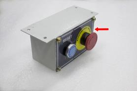
With the Emergency Stop button in the disabled position all motion and spindle function stops, the Reset button is disabled , and the blue Reset LED goes off. From the PathPilot interface, on the Status tab, the Machine OK light illuminates yellow.
-
From the PathPilot interface, select Exit.
-
When prompted, select OK.
-
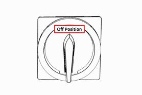
Once the PathPilot interface indicates that it's safe to power off the machine, turn the Main Disconnect switch to OFF.
Remove 4th Axis Power Plug and Inspect Pins
-
Remove 4th axis power cable from the machine.
-
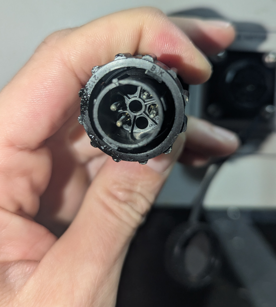
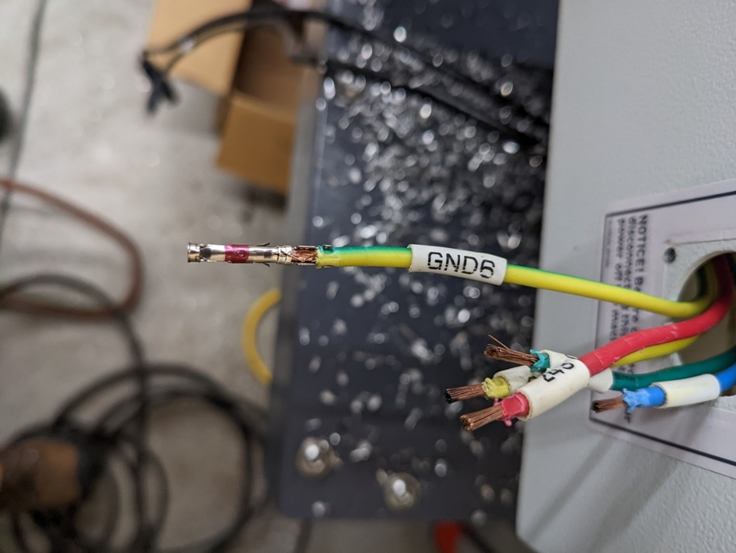
Inspect the 4th axis side male pins. Look for any burning or discoloration.
-
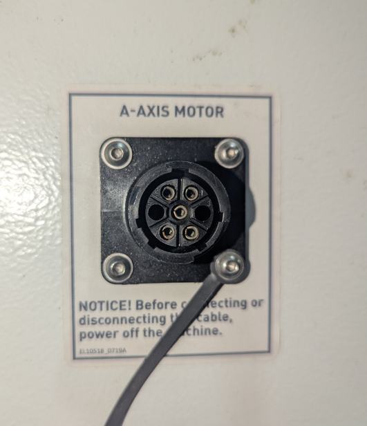
Then inspect the machine bulkhead female pins. Again, check for any burning or discoloration. Also, check if any of these female pins are pushed back in the connector out of position.
-
If either end is burnt or discolored, replacing the pins is needed.
Replace Pins
Tools
-
#1 Phillips Screwdriver
-
Magnetic Dish
-
Needle Nose Pliers
-
Metric Allen Key Set
Parts Needed
-
Machine Side Connector (30235) and 5x Female Pins (30774)
-
Alternatively, machine side wire harness (31189). Includes assembled 30235, 30774, 36in wires. Included 6ft wire not used.
-
-
Motor Side Connector (30480) and 5x Male Pins (30777)
Pin Replacement
-
Power off the machine. Disconnect the 4th axis cable from the machine side connector. If you are replacing the motor side connector, remove the 2 Phillips screws holding the clamp and unscrew the rear portion of the connector. If you are replacing the machine side connector, unscrew the connector from the electrical cabinet. Push or pull out the original pins from the connector.
-
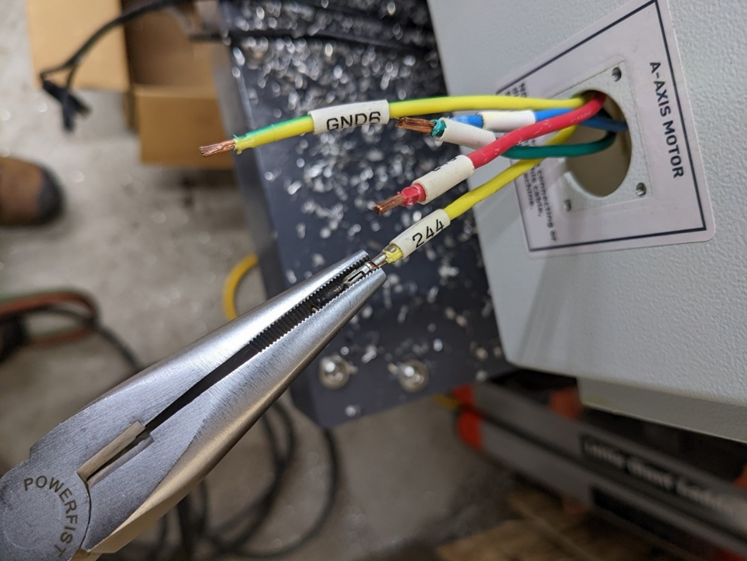
Use needle nose pliers or a punch less than .100” (2.54mm) diameter to push/pull the original pin from the wire. Replace the pin and crimp around the wire with needle nose pliers to secure pin. When crimping ensure that the pin’s inner tabs are secured around bare wire and the bottom tabs are secured around insulation as shown below.
-
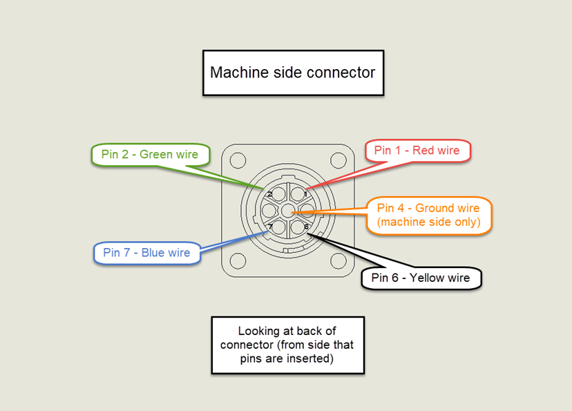
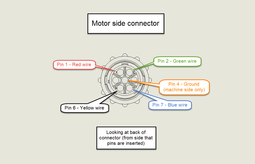
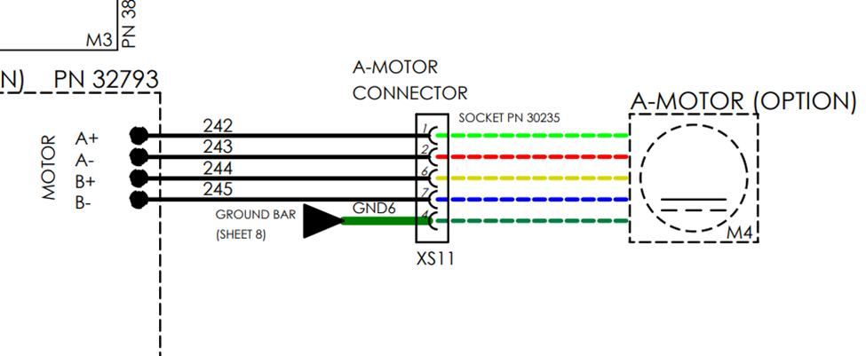
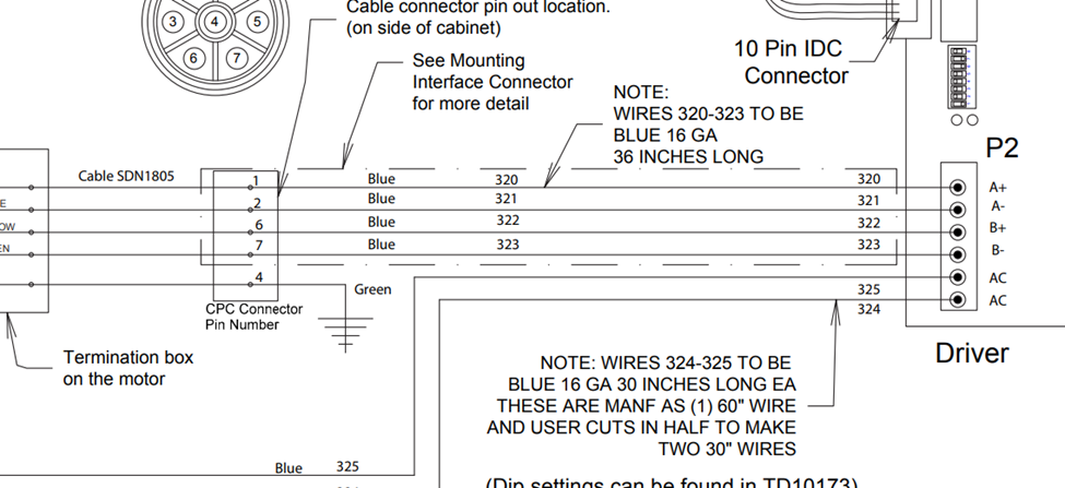
After securing all pins, insert the pins into the connector according to the chart below. The pin position differs between which connector you are working on, ensure that you are looking at the correct image. If your machine side wires are not colored according to the below image, skip to the next step.
-
The machine side wire numbers will differ depending on the machine model. The two pictures below show the PCNC and M/MX wire numbers as examples. Trace the wires as needed to make connections to the machine side connector. The A+ wire on the stepper driver will connect to pin 1 of the machine side connector, A- to pin 2, Ground to pin 4, B+ to pin 6 and B- to pin 7.
-
With a light tug, ensure that each pin is fully seated in the connector. Reassemble the connector (motor side) or remount it (machine side). Reconnect the 4th axis cable and power on the machine. Test the 4th axis rotation at jogging and rapid speeds.
To order part numbers not listed on http://Tormach.com, email orders@tormach.com!