770MX Enclosure Kit
It is recommended to install the ATC, if applicable, before finishing the enclosure installation.
Purpose
This document gives instructions on assembling and installing an enclosure on your mill.
Product Information
Product: 770MX Enclosure Kit (PN 39045)
NOTE: If any items are missing, we can help. Create a support ticket with Tormach Technical Support at tormach.com/how-to-submit-a-support-ticket for guidance on how to proceed.
Required Tools
This procedure requires the following tools. Collect them before you begin.
-
Metric Hex wrench set
-
Permanent marker
-
Shears or knife
Installation
Complete the following steps in the order listed:
Install the Enclosure Panels
Tip! To install the enclosure panels, work from the left to the right of the machine.
To make it easier to install all components, don't install the side windows until later in the procedure.
Keep all screws one quarter-turn loose while installing the enclosure panels. This makes it easier to align the panels. Once you're done installing the enclosure, fully tighten all screws.
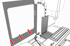
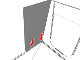
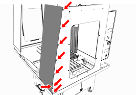
Install the Left Rear Panel
-
Attach the column cover to the machine column with three M6 × 1.0 - 12 screws.
-
Attach the left rear panel to the column cover with four M5 × 0.8 - 10 screws.
-
Attach the left rear panel to the left chip pan with three M6 × 1.0 - 12 screws.
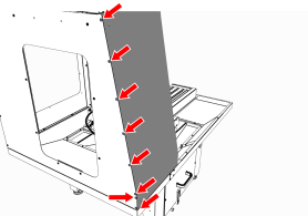
Install the Left Side Panel
-
Attach the left side panel to the left rear panel with five M5 × 0.8 - 10 screws.
-
Attach the left side panel to the left chip pan with five M6 × 1.0 - 12 screws.
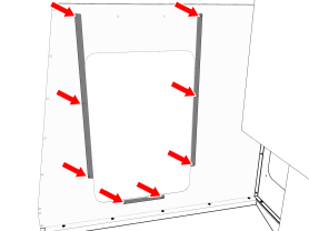
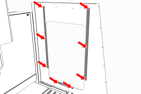
Install the Left Side Window Retainers
NOTE: To make it easier to install all components, don't install the side windows yet. Wait until later in the procedure.
-
Push a strip of rubber window trim on to the edges of:
-
Two vertical window retainers
-
One horizontal window retainer
-
-
When finished, use shears or a knife to cut the excess trim.
-
Loosely install two vertical window retainers on both sides of the left side panel's window opening with two sets of three M5 × 0.8 - 10 screws.
Don't fully tighten the screws. Leaving the window retainers loose makes it easier to install the side windows. -
Loosely attach one horizontal window retainer to the bottom of the left side panel's window opening with two M5 × 0.8 - 10 screws.
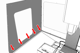
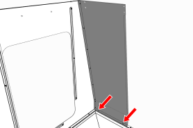
Install the Left Front Panel
-
Attach the left front panel to the left chip pan with threeM6 × 1.0 - 12 screws.
-
Attach the left front panel to the left side panel with seven M5 × 0.8 - 10 screws.
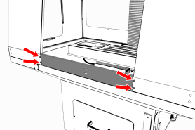
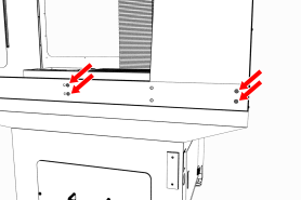
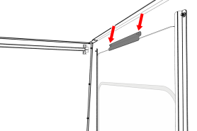
Install the Enclosure Splice Plate
-
Find the three installed M5 × 0.8 - 10 screws on the right side of the electrical cabinet.
-
Remove and set aside the three M5 × 0.8 - 10 screws.
-
Attach the right rear side panel to the electrical cabinet with the three M5 × 0.8 - 10 screws that you set aside in Step 2.
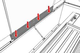
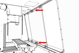
Install the Right Rear Panel
-
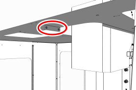
Find the three installed M5 × 0.8 - 10 screws along the top of the electrical cabinet.
-
Remove and set aside the three M5 × 0.8 - 10 screws.
-
Attach the right rear top panel to the electrical cabinet with the three M5 × 0.8 - 10 screws that you set aside in Step 2.
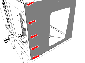
Install the Right Side Panel
-
Attach the right side panel to the enclosure splice plate with four M5 × 0.8 - 10 screws.
-
Attach the right side panel to the right chip pan with four M6 × 1.0 - 12 screws.
Install the Right Side Window Retainers
NOTE: To make it easier to install all components, don't install the side windows yet. Wait until later in the procedure.
-
Push a strip of rubber window trim on to the edges of:
-
Two vertical window retainers
-
One horizontal window retainer
When finished, use shears or a knife to cut the excess trim.
-
-
Loosely install two vertical window retainers on both sides of the right side panel's window opening with two sets of three M5 × 0.8 - 10 screws.
Don't fully tighten the screws. Leaving the window retainers loose makes it easier to install the side windows. -
Loosely attach one horizontal window retainer to the bottom of the right side panel's window opening with two M5 × 0.8 - 10 screws.
Install the Right Front Panel
-
Attach the right front panel to the right chip pan with two M6 × 1.0 - 12 screws.
-
Attach the right front panel to the right side panel with seven M5 × 0.8 - 10 screws.
Install the Left Top Panel
-
Attach the left top panel to the panels on the left side of the enclosure with 12 M5 × 0.8 - 10 screws.
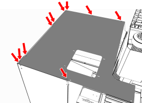
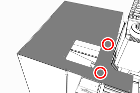
-
Attach two cable tie anchors to the left top panel with two M5 × 0.8 - 10 screws.
Install the Right Top Panel
-
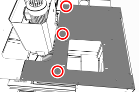
Attach the right top panel to the panels on the right side of the enclosure with nine M5 × 0.8 - 10 screws.
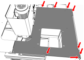
-
Connect the left and right top panels with one M5 × 0.8 - 10 screw.
-
Attach three cable tie anchors to the right top panel with three M5 × 0.8 - 10 screws.
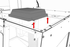
Install the Upper Front Panel
-
Attach the front upper panel (with the threaded holes facing up) to the right and left front panels with two sets of two M5 × 0.8 - 10 screws.
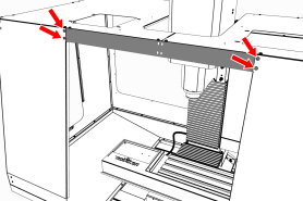
-
Attach the front upper panel to the right and left top panels with four M5 × 0.8 - 10 screws.
Install the Front Lower Panel
-
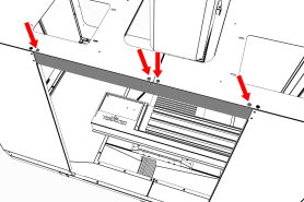
Attach the front lower panel to the right and left front panels with two sets of two M5 × 0.8 - 10 screws.
-
Attach the front lower panel to the right and left chip pans with four M5 × 0.8 - 10 screws.
Install the Rear Splash Shield
-
Attach the rear splash shield to the right chip pan below the electrical cabinet with four M6 × 1.0 - 12 screws.
Install the Linear Rails
Complete the following steps in the order listed:
Assemble the Linear Rails
-
Find the four linear rails provided: use the two shorter linear rails on the right side of the enclosure. Use the two longer linear rails on the left side of the enclosure.
-
Assemble each linear rail in the following order:
-
Slide one linear rail mount onto one end of the linear rail.
Don't completely tighten the clamping screw on the linear rail mount. It's easier to install and align the linear rails with loose clamping screws. -
Slide one bumper onto the linear rail.
-
Slide two linear bearings onto the linear rail.
-
Slide one bumper onto the opposite end of the linear rail.
-
Slide one linear rail mount onto the opposite end of the linear rail.
Make sure that the linear rail mount's clamping screw faces the same direction as the linear rail mount that you installed in Step A.
-
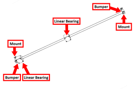
-
Repeat Step 2 for the remaining three linear rails.
Install the Linear Assemblies
-
Align one short linear rail assembly to the two holes on the inside of both the right front panel and the front lower panel.
The linear rail mount's clamping screws must face up.
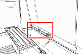
-
Attach the short linear rail assembly to the outside of both the right front panel and the front lower panel with two sets of two M6 × 1.0 - 12 screws.
-
Repeat Steps 1 to 2 for the remaining three linear rails, with the linear rail mount's clamping screws face in the following directions:
-
Up on the lower linear assemblies
-
Down on the upper linear assemblies
-
Install the Front Doors
Complete the following steps in the order listed:
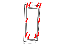
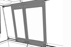
Assemble the Front Doors
-
Push a strip of rubber trim onto the edge of the window opening on each front door. Make sure that the trim starts at one end of the door handle mount, continues around the perimeter of the window, and ends at the opposite side of the door handle mount. When finished, use shears or a knife to cut the excess trim.
-
Remove and discard the protective plastic film from each window.
-
On the inside of one front door, put one window on top of the rubber trim.
-
Attach one dark gray, vertical window retainer to both sides of the front door's window opening with two sets of three M5 × 0.8 - 10 screws.
NOTICE! To prevent window damage from over-tightening, use your fingers to tighten the screws. -
Attach one dark gray, horizontal window retainer to the top and bottom of the front door's window opening with two sets of two M5 × 0.8 - 10 screws.
NOTICE! To prevent window damage from over-tightening, use your fingers to tighten the screws.
-
Repeat Steps 1 through 5 to assemble the remaining front door.
Install the Front Door Assemblies
Each front door is attached to the enclosure by securing it to the linear bearings: the wider door is mounted on the left side of the enclosure, and the narrower door is mounted on the right side of the enclosure.
To install the front doors:
-
Starting with the top linear assembly, attach the narrow door to the two upper linear bearings with two sets of four M5 × 0.8 - 10 screws.
-
Move the bottom of the narrow door into alignment with the bottom linear assembly. Then, attach the narrow door to the two bottom linear bearings with two sets of four M5 × 0.8 - 10 screws.
-
Repeat Steps 1 to 2 to attach the wide door to the top and bottom linear rail assemblies on the remaining side of the enclosure.
-
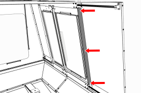
To the edge of the front door that's closest to the left side of the enclosure, attach one door seal with three M5 × 0.8 - 10 screws.
-
Repeat Step 4 for the remaining front door.
-
Attach the handles to both front doors with two sets of two M8 x 1.25 - 20 screws and two sets of two M8 flat washers.
-
Push one square tube plug into the bottom of each door handle.
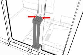
Install the Door Latch
-
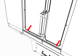
Attach the door latch strike plate on the left front door with a Phillips screwdriver and two M3 screws.
-
Attach the door latch in the pocket on the right door with two M3 screws.
Install the Floodlights
-
Use a multimeter to verify the ground connection of both floodlights:
-
Measure the resistance between the floodlight's power connector ground pin (the middle pin on the three-prong connector) and the floodlight's bracket screw.
-
Read the OHMS value that displays. The value should be less than 5 OHMS. If the value is greater than 5 OHMS, don't install the floodlight. Create a support ticket with Tormach Technical Support at tormach.com/how-to-submit-a-support-ticket for guidance on how to proceed.
-
-
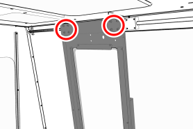
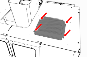
Position one floodlight over the opening on the right top panel. Take care not to drop the light through the opening into the enclosure.
-
Attach one floodlight retainer to either side of the lights with two sets of two M5 × 0.8 - 10 screws.
Verify that the floodlight is centered over the opening before hand-tightening the floodlight retainers.
-
Repeat Steps 1 to 3 to install the floodlight on the left side.
-
Connect the short power cable from the Enclosure Cable Kit to the plug on the right floodlight.
-
Connect the long power cable from the Enclosure Cable Kit to the plug on the left floodlight.
-
Route the power cables from the floodlights to the electrical cabinet.
-
Plug the floodlights into the Enclosure Lights outlet on the back of the electrical cabinet.
-
Attach the floodlights' power cables to the five wire tie anchors on the left and right top panels with five wire ties.
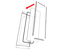
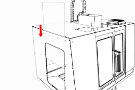
Install the Side Windows
-
Rubber trim is required to prevent leaks around the window openings: push a strip of rubber trim to the edge of the window opening on each side panel. Verify that the trim covers the entire perimeter of the window. When finished, use shears or a knife to cut the excess trim.
-
Remove and discard the protective plastic film from the windows.
-
Slowly slide one window through the left top panel's window opening and into the two installed vertical window retainers. Take care to not scratch the window. When finished, verify that the window rests on the bottom horizontal window retainer.
-
Push a strip of rubber trim onto the edge of one horizontal window retainer. When finished, use shears or a knife to cut the excess trim.
-
Attach one horizontal window retainer above the window on the left side panel with two M5 × 0.8 - 10 screws.
-
Tighten all screws on the window retainers to secure the window.
NOTICE! To prevent window damage from over-tightening, use your fingers to tighten the screws. -
Repeat Steps 1 through 6 for the window on the right side panel.
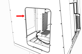
Install the Access Panel
-
Push three round hole plugs into the three holes on the left rear panel.
-
Push a strip of rubber trim to the edge of the access panel opening on the left rear panel. Verify that the trim covers the entire perimeter of the opening. When finished, use shears or a knife to cut the excess trim.
-
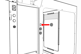
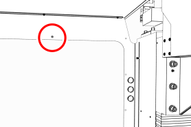
Find the threaded hole toward the top center of the left rear panel. Then, loosely install one M5 × 0.8 - 10 screw from the inside of the enclosure.
This screw supports the access panel while you install the remaining fasteners.
-
Tilt the access panel and put it through the opening on the left rear panel. Then, hang it inside the enclosure on the installed M5 × 0.8 - 10 screw.
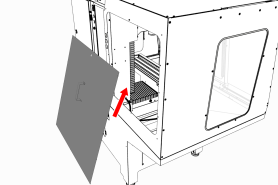
-
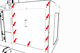
Attach the access panel to the left rear panel from the outside of the enclosure with 11 M5 × 0.8 - 10 screws.
Install the Stainless Steel Wear Guard
-
Find the stainless steel wear guard that you set aside earlier.
-
Attach it to the lower front panel with two M5 × 0.8 - 10 screws.
Use the Maintenance Labels
Write the Date on the Maintenance Labels
The machine has one maintenance label on each window.

Write down today's date on each label with a permanent marker.
You have completed assembling and installing the 770MX Enclosure.
Replace the Windows
When required, replace the windows with the following parts:
-
Window, 770, Side (PN 37625)
-
Window, 770M, Left Door (PN 37623)
-
Window, 770M, Right Door (PN 37624)
Exploded Views and Parts Lists
Enclosure Exploded View
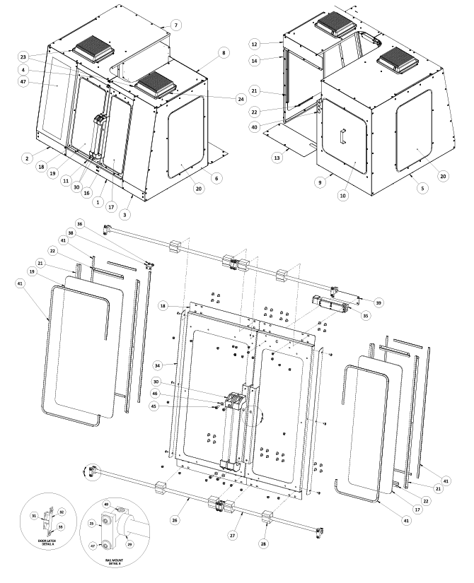
Enclosure Parts List
|
ID |
Description |
Quantity |
|
1 |
Enclosure Panel, 770, Lower Front (PN 37600) |
1 |
|
2 |
Enclosure Panel, 770MX, Left Front (PN 39551) |
1 |
|
3 |
Enclosure Panel, 770MX, Right Front (PN 39552) |
1 |
|
4 |
Enclosure Panel, 770, Upper Front (PN 37605) |
1 |
|
5 |
Enclosure Panel, 770MX, Left Side (PN 39553) |
1 |
|
6 |
Enclosure Panel, 770MX, Right Side (PN 39554) |
1 |
|
7 |
Enclosure Panel, 770, Left Top (PN 37614) |
1 |
|
8 |
Enclosure Panel, 770, Right Top (PN 37615) |
1 |
|
9 |
Enclosure Panel, 770, Left Rear (PN 37616) |
1 |
|
10 |
Enclosure Panel, 770, ATC (PN 37617) |
1 |
|
11 |
Chip Tray Rail, 770 (PN 37662) |
1 |
|
12 |
Enclosure Panel, 770, Right Rear (PN 37619) |
1 |
|
13 |
Enclosure Panel, 770MX, Splash Shield (PN 39555) |
1 |
|
14 |
Enclosure Panel, 770, Splice Plate (PN 38480) |
1 |
|
15 |
Enclosure Panel, 770, Column Splice (PN 37618) |
1 |
|
16 |
Enclosure Door, 770, Right (PN 37609) |
1 |
|
17 |
Window, 770M, Right Door (PN 37624) |
1 |
|
18 |
Enclosure Door, 770, Left (PN 37608) |
1 |
|
19 |
Window, 770M, Left Door (PN 37623) |
1 |
|
20 |
Window, 770, Side (PN 37625) |
2 |
|
21 |
Enclosure Window Retainer, 770, Vertical (PN 37620) |
8 |
|
22 |
Enclosure Window Retainer, 770, Horizontal (PN 37621) |
8 |
|
23 |
LED Floodlight, 50 W (PN 37341) |
2 |
|
24 |
Flood Light Retainer (PN 38222) |
4 |
|
25 |
Linear Rail Mount (PN 37622) |
8 |
|
26 |
Left Door Rail, 770 (PN 37606) |
2 |
|
27 |
Right Door Rail, 770 (PN 37607) |
2 |
|
28 |
Linear Bearing (PN 37610) |
8 |
|
29 |
Door Bumper (PN 38357) |
8 |
|
30 |
Handle, 400 mm (PN 37611) |
2 |
|
31 |
Enclosure Ball Latch, Male (PN 38483) |
1 |
|
32 |
Enclosure Ball Latch, Female (PN 38482) |
1 |
|
33 |
Washer, Flat, M5, Stainless Steel (PN 37939) |
2 |
|
34 |
Door Seal (PN 37613) |
2 |
|
35 |
Locking Door Switch (PN 37352) |
1 |
|
36 |
Nut Bar (PN 37585) |
1 |
|
37 |
Locking Switch Key (PN 37529) |
1 |
|
38 |
Switch Key Bracket (PN 37586) |
1 |
|
39 |
Locking Door Switch Installation/Cover Plate (PN 38272) |
1 |
|
40 |
Round Plug, 32 mm (PN 37598) |
3 |
|
41 |
Sealing Strip, Rubber (PN 38356) |
21 |
|
42 |
Screw, Button Head Cap (Flanged), M6 × 1 - 12, Stainless Steel (PN 38206) |
77 |
|
43 |
Screw, Button Head Cap (Flanged), M5 × 0.8 - 10, Stainless Steel (PN 38205) |
153 |
|
44 |
Screw, Socket Head Cap, M5 × 0.8 - 20 (PN 30357) |
8 |
|
45 |
Screw, Socket Head Cap, M8 × 1.25 - 22 (PN 37190) |
4 |
|
46 |
Washer, Flat, M8 (PN 30531) |
4 |
|
47 |
Decal, Enclosure, 770MX, Front Left Panel (PN 39037) |
1 |
To view a PDF version of your manual, go to Tormach document TD10712.
If you have additional questions, we can help. Create a support ticket with Tormach Technical Support at tormach.com/how-to-submit-a-support-ticket for guidance on how to proceed.