Product Information
Purpose: This document details installation, spindle calibration, and operation of the PCNC 1100 Spindle Drive Upgrade Kit.
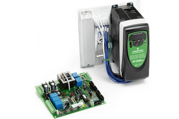
Product: Spindle Drive Upgrade Kit for PCNC 1100 Mills (PN 31090)
|
Quantity |
Description |
|
4 |
M4 × 10 mm Spacer (PN 31088) |
|
4 |
M4 × 10 mm Screw (PN 30537) |
|
4 |
M4 Flat Washer (PN 31087) |
|
1 |
|
|
1 |
|
|
1 |
D40194 VFD Upgrade Assembly |
NOTE: If any items are missing, we can help. Create a support ticket with Tormach Technical Support at tormach.com/how-to-submit-a-support-ticket for guidance on how to proceed.
IMPORTANT! This upgrade kit will not work with ground fault interrupters (GFI or RCCB in Europe).
Required Tools
This procedure requires the following tools. Collect them before you begin.
-
#2 Phillips Screwdriver
-
1/4 in. Flat-Blade Screwdriver
-
1/8 in. Flat-Blade Screwdriver
-
Wire Cutter
-
Wire Stripper
Installation
NOTE: We're continuously improving our products, so your machine may vary from the photos in our documents and videos. For example, newer upgrade kits use a Commander C200 VFD, and older upgrade kits use a Commander SK VFD. While the images may vary, the concepts still apply.
Removing Existing Drive
WARNING! Electrical Shock Hazard: You must power off the machine before making any electrical connections. If you don't, there's a risk of electrocution or shock.
-
Power off the machine and the PathPilot controller.
-
Push in the machine's red Emergency Stop button, which removes power to motion control.
-
From the PathPilot interface, select Exit.
-
Turn the Main Disconnect switch to OFF on the side of the electrical cabinet.
-
-
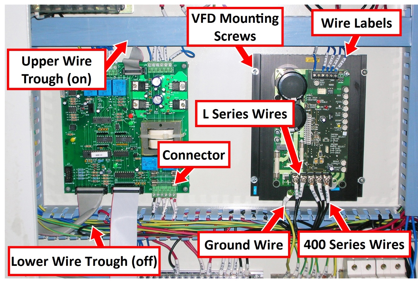
Remove the cover of the upper and lower wire trough inside the electrical cabinet.
-
Detach and remove all wires from the existing drive.
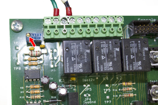
NOTE: If any wires are missing wire labels, note their connection labels as shown in the following image, and tag them with the extra wire labels (included).
-
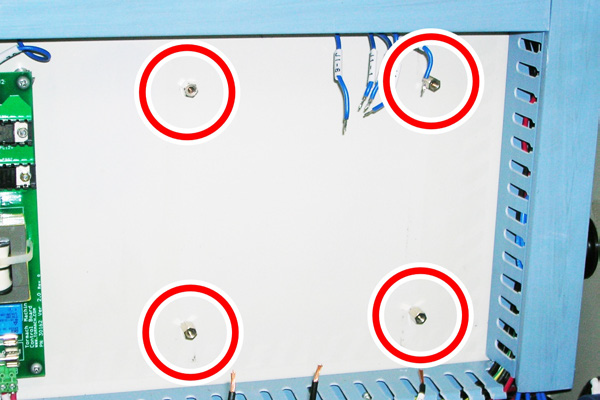
Remove and discard four VFD mounting screws that secure the drive to the back panel of the electrical cabinet.
Re-labeling Lower Drive Wires
-
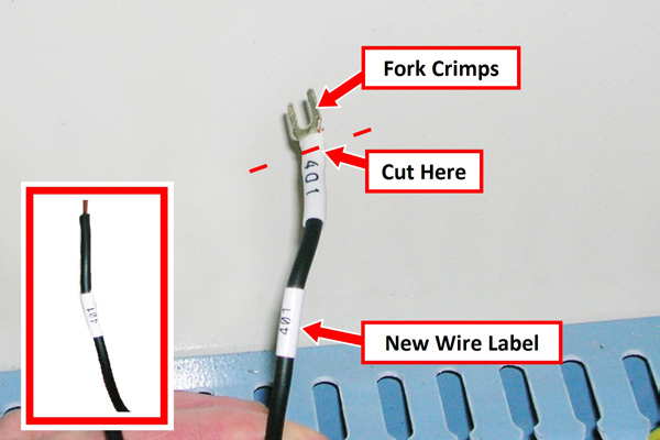
Identify wire L16, L26, 400, 401, and 402 in the lower wire trough.
-
Match each wire label (included) to each wire; put the new wire label below the existing label, as shown in the following image.
-
Using a wire cutter, remove existing fork crimps at the location indicated in the image above.
NOTE: Do not to remove any more wire than is needed. -
Remove the original wire label and strip the wire 1/4 in. from its end (as shown in the image's inset).
Mounting VFD Motor Drive Assembly
-
Put four M4 × 10 mm spacers (included) into the four mounting holes that were previously used for the original drive.
-
Using four M4 × 10 mm screws and four M4 flat washers (both included), mount the VFD motor drive assembly onto the spacers that you installed in Step 1.
NOTE: On some mills, the vertical space between the wire troughs may be too tight to fit the VFD motor drive assembly. In this case, adjust the lower wire trough and remount.
IMPORTANT! Be careful to not damage any wires in the wire trough.
Wiring VFD Motor Drive Assembly
-
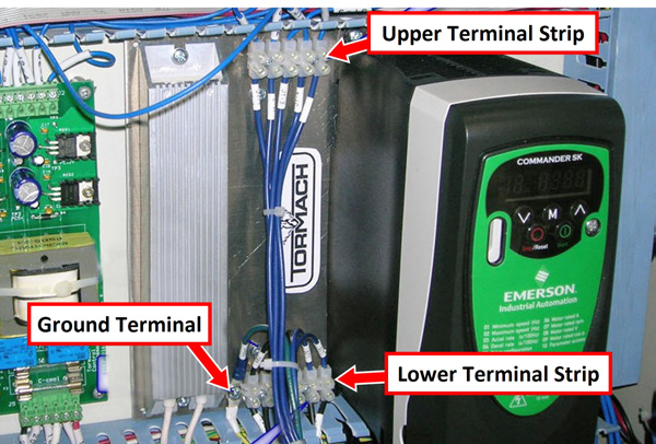
Identify wires from the upper wire trough; these connect to the upper terminal strip on the VFD motor drive assembly.
-
Refer to "Drawings” to make specific wiring connections on the upper terminal strip.
-
Repeat Steps 1 through 2 for the lower wire trough and its corresponding wiring connections on the lower terminal strip.
NOTE: If the space is too tight to connect the wires, remove the two screws holding down each terminal strip and make the wiring connections. Remount both terminal strips when wiring is complete. -
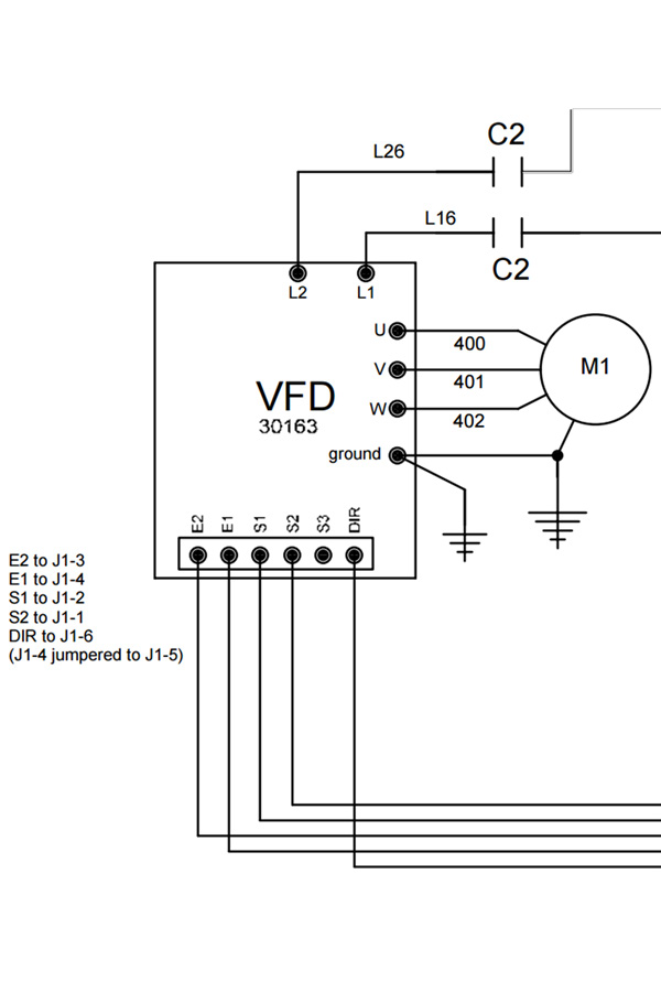
Some older mills may have wire numbers that do not correspond to wires labeled J1 in this upgrade kit. Refer to the table below for correct wiring on older mills:
|
Original Spindle Drive Wire Number |
If equipped with SK VFD (PN 31036) |
If equipped with C200 VFD (PN 53811) |
|
S2 |
J1-1 |
2 |
|
S1 |
J1-2 |
1 |
|
E2 |
J1-3 |
11 |
|
E1 |
J1-4 |
9 |
|
DIR |
J1-6 |
12 |
-
Using the wiring diagram (in "Drawings"), make the correct ground wire connection.
IMPORTANT! Ensure there are no loose wire strands at the terminal strip that may come in contact with another wire.
Mounting New Machine Control Board
-
Remove all wire harnesses from the existing control board.
NOTE: Discrete wires are connected through the use of multi-terminal connectors that mount to the control board. Do not remove individual wires; remove the entire connector from the control board. -
Remove the four mounting screws and the original control board from the electrical cabinet. Replace it with the included machine control board, and reconnect the wire harnesses.
New Configuration
-
The VFD motor drive requires a different machine configuration in PathPilot.
-
Power on the machine and the PathPilot controller.
-
Turn the Main Disconnect switch to ON on the side of the electrical cabinet.
-
Twist out the machine's red Emergency Stop button, which enables movement to the machine axes and the spindle.
-
Press the machine's Start button (next to the Emergency Stop button).
-
Bring the machine out of reset and reference it.
-
-
Set the spindle mode switch to AUTO on the operator panel.
-
From the PathPilot interface, type ADMIN CONFIG in the MDI line.
-
Following on-screen instructions, select correct configuration for your specific machine.
Spindle Calibration
To improve spindle speed accuracy, calibrate the controller to the Spindle Drive Upgrade Kit. This procedure is not necessary for mill operation.
This procedure requires access to the electrical cabinet while the mill is powered on.
WARNING! Electrocution Hazard: When servicing the machine from inside the electrical cabinet, always use caution. Points in the electrical cabinet have high voltages that can electrocute or shock you. Even after you've powered off the machine, electronic devices in the electrical cabinet may retain dangerous electrical voltages. Only qualified electrical machinery technicians should perform maintenance or troubleshooting procedures inside the electrical cabinet while power is still on.
-
From the PathPilot interface, toggle the spindle belt position: click Spindle Range until the LED light is illuminated next to LO.
IMPORTANT! Ensure the spindle belt is in the low position. A mismatch between the spindle range button and actual spindle belt position will result in the commanded speed being different from the indicated RPMs. -
Set the spindle speed to 500 RPM:
-
In the MDI line, type S500 and press Enter.
-
In the Spindle DRO, type 500 and press Enter.
WARNING! Entanglement Hazard: The machine operates under automatic control — it can start at any time and crush, cut, entangle, or pinch body parts. Always keep clear of positions on the machine where unexpected or unintended machine motion could cause harm.
-
-
Ensure there are no tools in the spindle; start the spindle.
-
Inspect the value displayed on the front panel of the VFD. The recommended range is 34-36 Hz.
-
If the value is outside of the 34-36 Hz range, use a small, flat-blade screwdriver to adjust the trim potentiometer screw on the machine control board until the value is within range.
NOTE: If better accuracy is needed, use a tachometer to measure actual spindle speed.
Operation
The VFD motor drive functions similarly to the original VFD, with some important differences:
-
The VFD motor drive allows the spindle to run both slower and faster than the original VFD. The scale printed around the spindle speed dial on the operator panel will not match the new speed range.
-
In addition to a wider operating speed window, acceleration and deceleration is significantly faster. However, the drive will take an additional few seconds to power on after a drive reset (drive powered off). The drive is powered off under any one of the following conditions:
-
System power off
-
Spindle door opened (i.e., tool changes)
-
Spindle lockout key turned to Off position
-
E-stop depressed
-
Power Drawbar, if equipped, is activated
NOTE: When running G-code programs, ensure the VFD motor drive has a chance to spin up to top speed before beginning.
-
-
If the spindle is rotating in the opposite direction than commanded in either manual mode or auto mode, swap wires 401 and 402 at the drive.
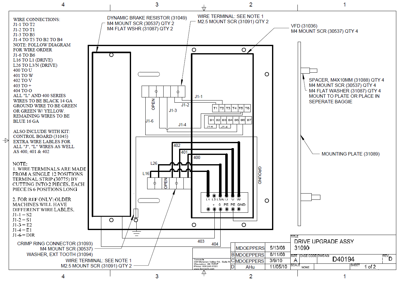
NOTE: After Spindle Drive Upgrade Kit is installed, attached drawing (D40194) supersedes VFD wiring diagrams in original Operator Manual.
Drawings
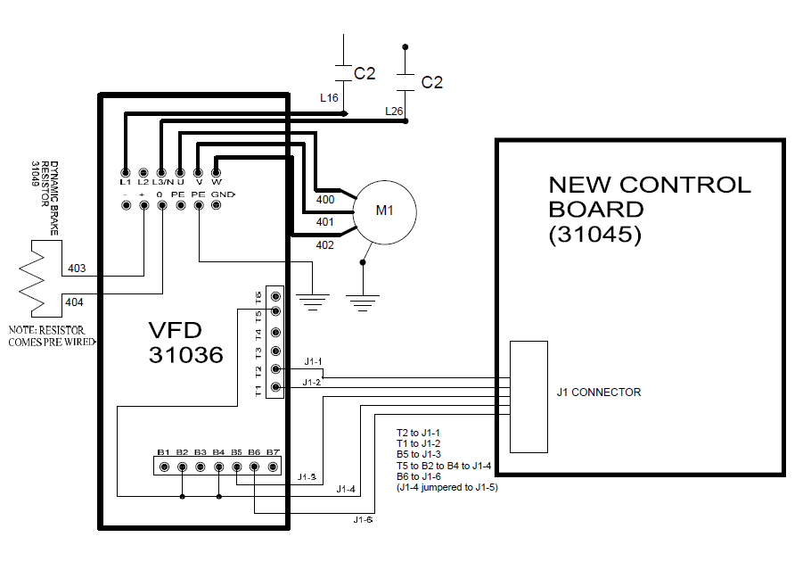
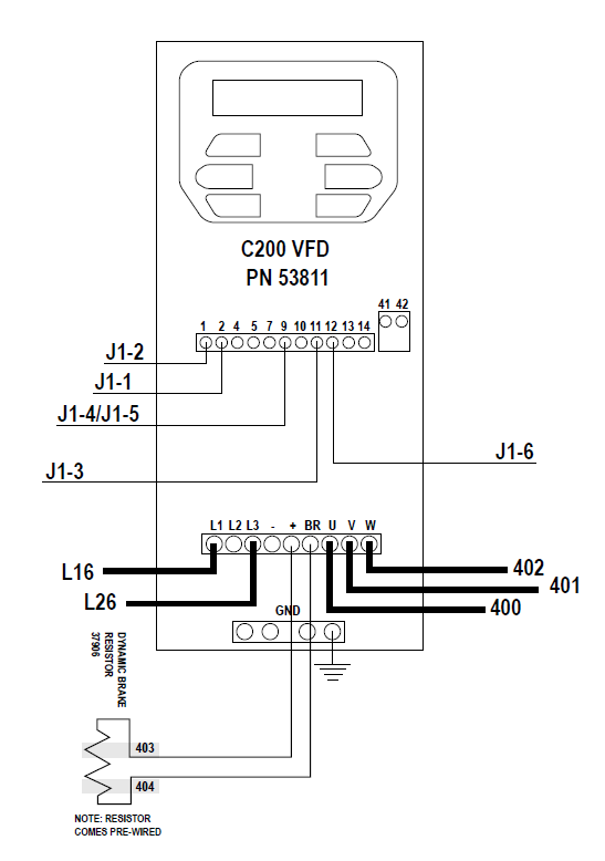
IMPORTANT! Two wiring diagrams are included. Newer upgrade kits use a Commander C200 VFD (PN 53811), and older upgrade kits use a Commander SK VFD (PN 31036). Use the wiring diagram specific to the VFD in your upgrade kit.
Wiring Diagram for SK VFD (PN 31036)
Wiring Diagram for C200 VFD (PN 53811)
D40194 - VFD Upgrade Assembly