Background
The intention of this kit is to enable the user to simply and safely disassemble and reassemble the PCNC 770 without damaging the equipment in the process. The user takes on the responsibility of following these instructions and using good commonsense during lifting and transporting of components. The moving kit can also be used on the 770M, with the same process, although slight differences exist.
Introduction
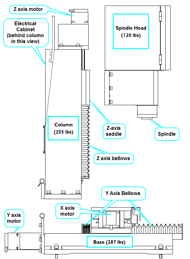
The PCNC 770 Mill can be broken down to 3 major components: the Base, the Column, and the Spindle Head. The user may elect to only partially disassemble their machine, in which case awareness of component weight and weight distribution is critical.
Glossary of terms
Base: This is the lower part of the mill containing the main lower casting, saddle, bed, X and Y axis ball screws and motors.
Bed: This the moving table of the mill. It contains 3 T-slots along its length and moves in the X and Y direction. Collet (R8): This is the TTS R8 Collet that comes with both this moving kit and Tormach Tooling System sets.
Column: This is the middle part of the mill containing the main vertical casting, Z axis saddle, and the Z axis ball screw and motor as well as the electrical cabinet.
Critical Surface: This is any precision surface between two major mating parts. These surfaces have been hand scraped for a precise fit.
Hinge: This is the devise used to simplify Column disassembly and reassembly.
Spindle Fixture: This is the devise used to affix and support the spindle head to the bed during disassembly and reassembly.
Spindle Head: This is the portion of the mill containing the main spindle casting, spindle motor, pulleys and spindle cartridge.
Taper Pin: this is a dowel pin that has a slight taper to it creating a wedge shape. The pins have a tapped hole in the top to facilitate removal.
Safety
WARNING! Obey all lifting device safety instructions! Do not over load the rated capacity of any lifting device! The User accepts all responsibility when lifting and transporting the mill or its components!
Here are some basic guidelines for lifting safety:
-
Always balance your load, be aware of loads shifting while lifting.
-
Always keep hands, feet and other body parts out from under a lifted load at all times
-
Be aware of your surroundings: avoid pinch points, slopes, uneven or rough rolling surfaces.
-
Be aware of where a lifted item will fall in the event of lift component failure.
-
Think through a lifting strategy before beginning. Make some test lifts to verify stability and lift capacity.
-
Go Slow and use common sense. Shortcuts and poor judgment can cause injury and damage components.
Warranty
Tormach does not warranty damage to the mill and other components that occur during disassembly, reassembly or moving.
What comes in your kit?
-
Protective wood covers (4)
-
Steel hinge (1)
-
Steel spindle fixture (1)
-
Pin extraction tool (1)
-
TTS R8 collet (1)*
-
M16x50 Tbolt (2)
-
M16 Hex Nut (2)
-
M16 Flat Washer (2)
-
M5x20 Screw (1)
-
M12x60 Screw (4)
-
M12x25 Screw (4)
-
M12 Hex Nut (4)
-
M12 Flat Washer (12)
-
M10x35 Screw (6)
-
M10x20 Screw (4)
-
M10 Hex Nut (4)
-
M10 Flat Washer (10)
-
*TTS R8 Collet is shipped separately from the rest of these components
Tools Required
-
Set of Metric Hex wrenches
-
Large and small adjustable wrench
-
Phillips screw driver
-
WD 40 (or similar oil)
-
Lifting equipment
Disassembly
Preparation
-
Remove the sides and top of the shipping crate your PCNC 770 came in.
-
Hook up computer or Tormach controller per the owners manual’s instructions along with a monitor, mouse and keyboard. Connect power to the mill per the manual and turn on.
-
Jog the Z axis up and remove the shipping block from beneath the spindle.
Spindle Head Removal
-
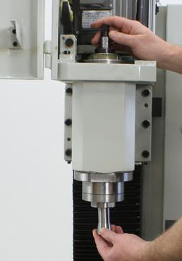
Insert the included draw bar (can be found in the box nailed to the shipping pallet), and the R8 collet that comes with the moving kit. These will screw into each other (do not tighten). See Fig. 2.
-
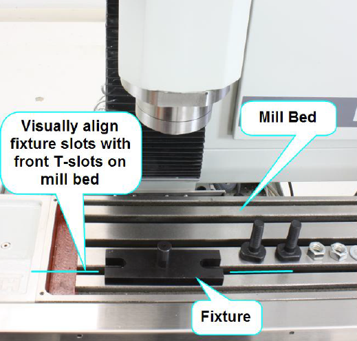
Position the spindle fixture to the front T-slot on the bed; do not attach fixture bolts at this time. See Fig 3.
-
Jog the Y axis position so that the fixture is under the spindle bore.
-
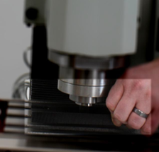
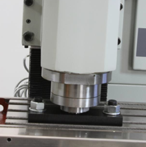
Partially lower the spindle over the fixture. It might be useful to manually lift the fixture into the spindle/collet (See Fig. 4), then slowly lower the spindle and fixture down to the mill bed until the collet is about half way down on the fixture.
-
Mount and tighten the T-bolts to the bed and fixture then lower spindle all the way onto fixture leaving about a ¼ inch gap between the Base of the fixture and the nose of the spindle. See Fig. 5.
-
Tighten the draw bar thus securing the spindle to the fixture.
-
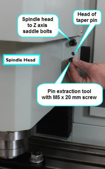
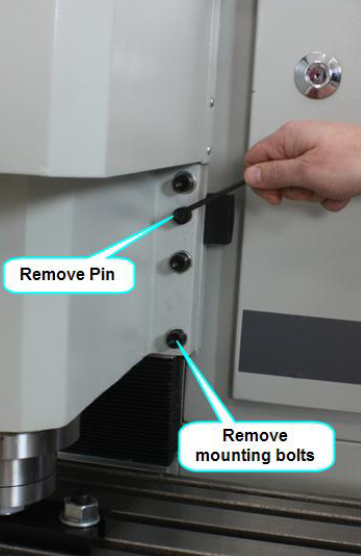
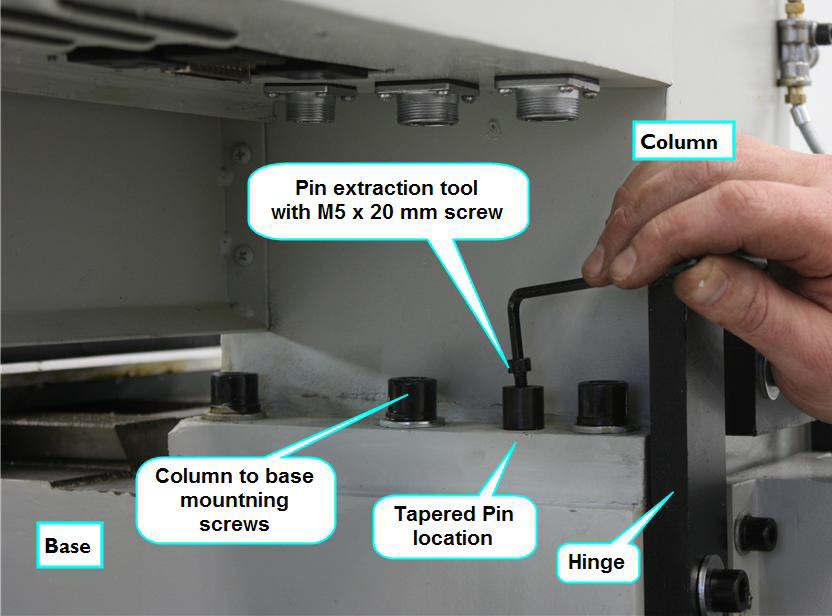
Remove the taper pins at the Z axis saddle. There are 2 tapered pins located 1 on each side of the spindle head. Each pin has a threaded hole. Use the pin extraction tool by placing the open side of the cup over the pin, and thread the screw through the hole in the cup into the pin. It may be necessary to scrape away a bit of paint from the head of the pin to get the screw in properly. Tightening down the screw will extract the pin. After a few turns the pin will simply pull out. Should the screw become lodged in the pin threads, take caution not to damage the pin’s surface as you free them. Set pins aside as you will be re-using these during reassembly. See Fig. 6.
-
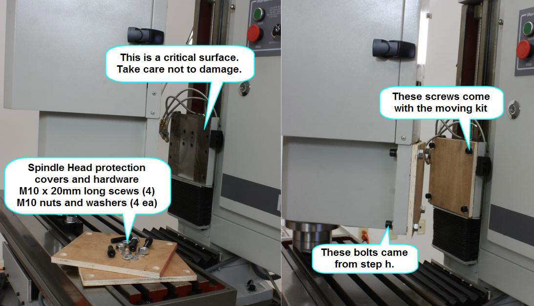
Remove the bolts connecting the spindle head to the saddle (these will be used later to mount the protective covers). See Fig.7.
-
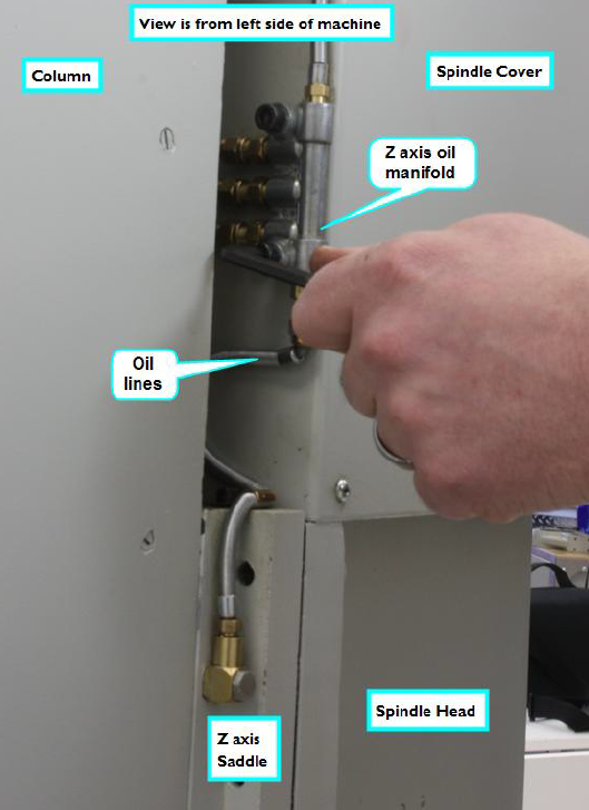
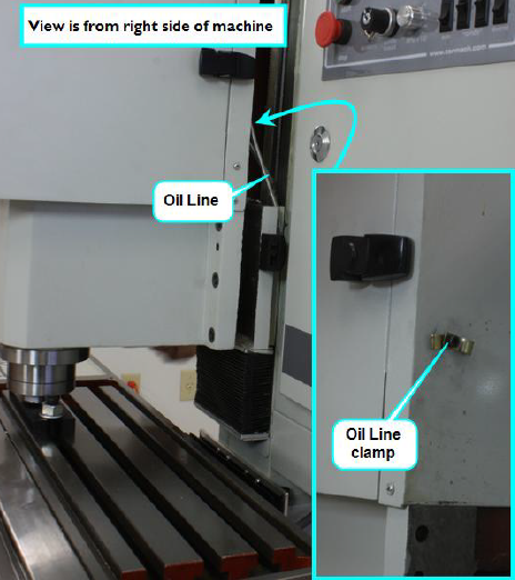
Remove the Z axis oil manifold bolts. See Fig. 8.
-
Move the Y axis to separate the spindle head from the Column, about 1-2 inches.
-
Loosen the lubrication line clamp located on the back face of the sheet metal spindle cover. See Fig. 9.
-
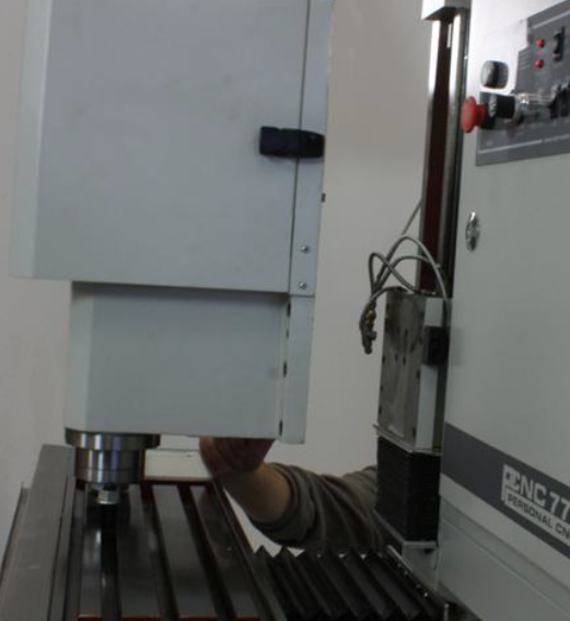
Move the Y axis to the maximum Y position (move table towards the front of the machine). See Fig. 10.
-
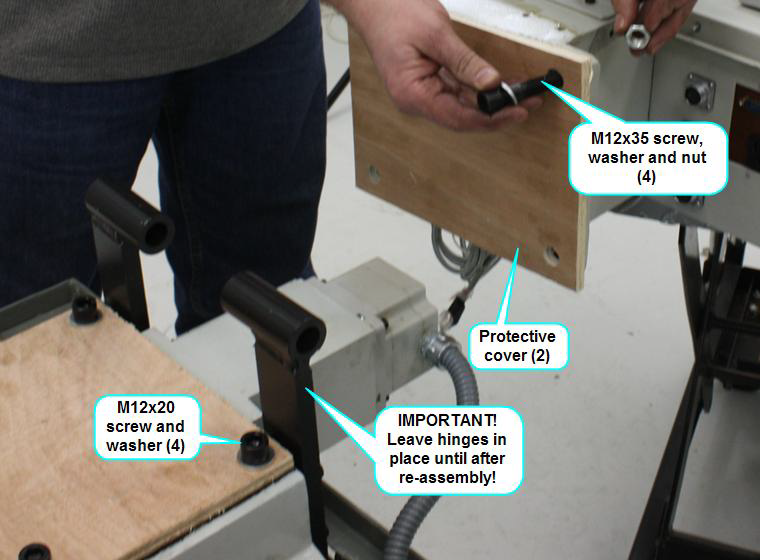
Mount protective cover (match hole patterns). Note: re-use the spindle head mounting bolts to mount the cover to the Column. See Fig. 11.
-
Power down the machine, disconnect all input power cords.
-
Lift and remove the spindle door cover
-
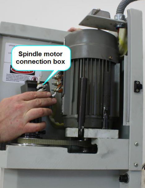
Remove the connection cover box on the spindle motor and disconnect the 3 black motor power leads and the ground wire. See Figure 12.
-
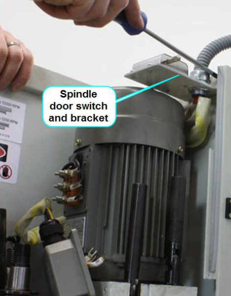
Remove the 3 screws connecting the spindle door switch to the rear cover. See Figure 13.
-
Loosen the drawbar. See Fig. 14.
-
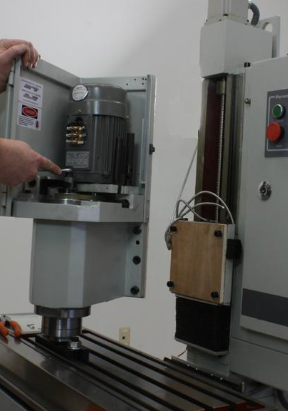
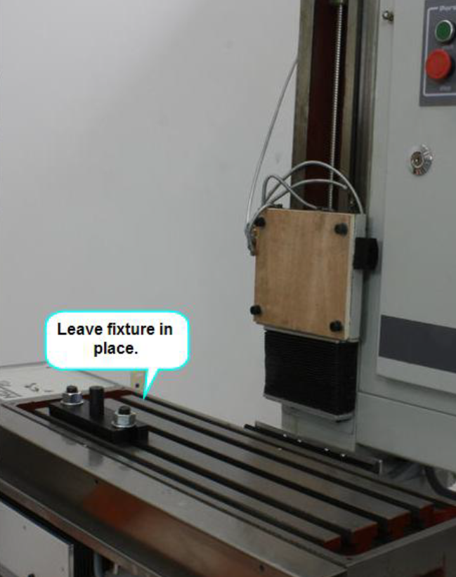
The spindle head can now be lifted and removed from the machine. Note, the weight of the head can cause the collet to remain collapsed over the fixture post. If the head will not come freely off the fixture, use a means to gently pry the head vertically. Less than 1” of vertical travel is needed to free the spindle. Ideally the fixture would be left in place on the bed to make reassembly easier. See Fig. 15. If the spindle will not come free from the fixture while mounted to the table, the fixture can be unbolted and removed with the spindle. Care should be taken to not let the spindle fall while loosening the fixture mounting bolts. Care should also be taken not to damage the bed.
WARNING! The spindle head weighs 120 pounds. Use proper lifting equipment and observe all safety precautions before lifting. The sheet metal cover is not a good place for lifting points.
Column Removal
-
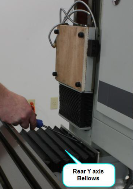
Remove the screws connecting the rear bellows cover to the Column. See Fig. 16.
-
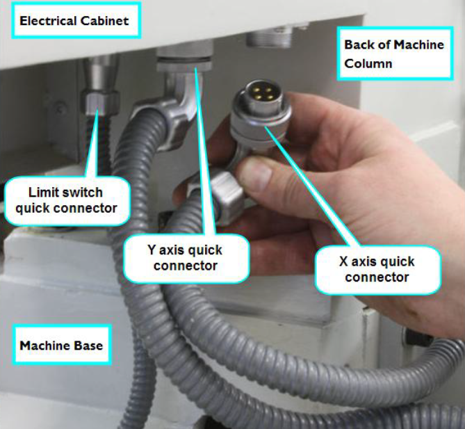
Underneath the electrical cabinet are 3 plugs. The 2 larger plugs are for the X and Y axis motors, the smaller one is for the x and y limit switches. Disconnect them from the cabinet by loosening the retaining nut and pulling down. See Fig. 17.
-
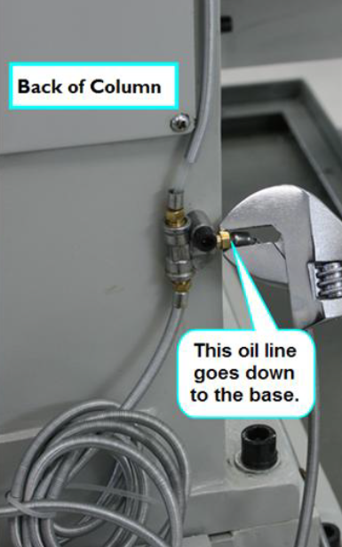
The lubrication system must be separated. Located on the back of the Column is a y-fitting. Loosen and remove the oil line fitting that goes down to the Base. See fig. 18.
-
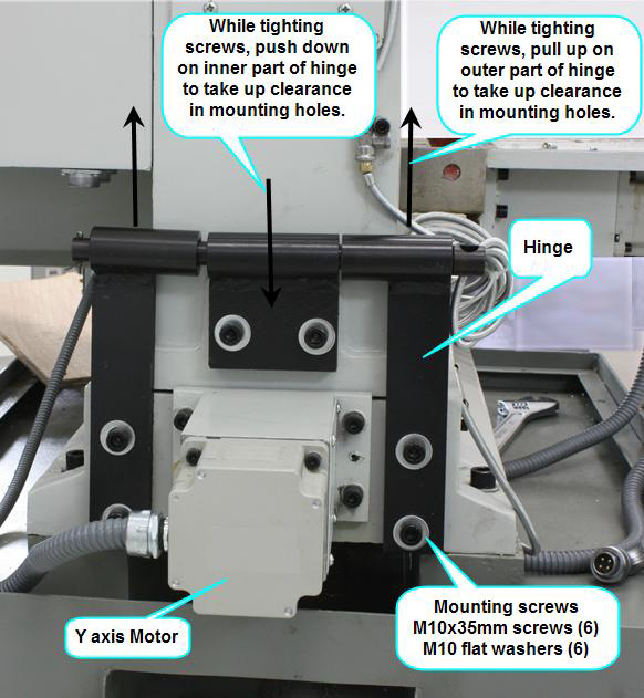
Mount the moving kit Hinge using the indicated screws. See Fig. 18. Note: it may be necessary to scrape away paint from the tapped holes in the Column and Base. The hinge is designed with a pin that fits loosely in the hinge flaps. Proper mounting means pushing up on the outer flaps when tightening, and down on the inner flap when tightening. This will help limit the possibility of damage to critical surfaces during disassembly and reassembly.
-
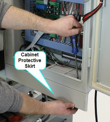
Mounted to the front face at the bottom of the electrical cabinet is a protective skirt used to deflect coolant off of the electrical connections. This skirt needs to be removed in order to access some of the Column mounting bolts. There are 3 nuts and screws along the top edge of the skirt and 2 screws on the side. See Fig. 19.
-
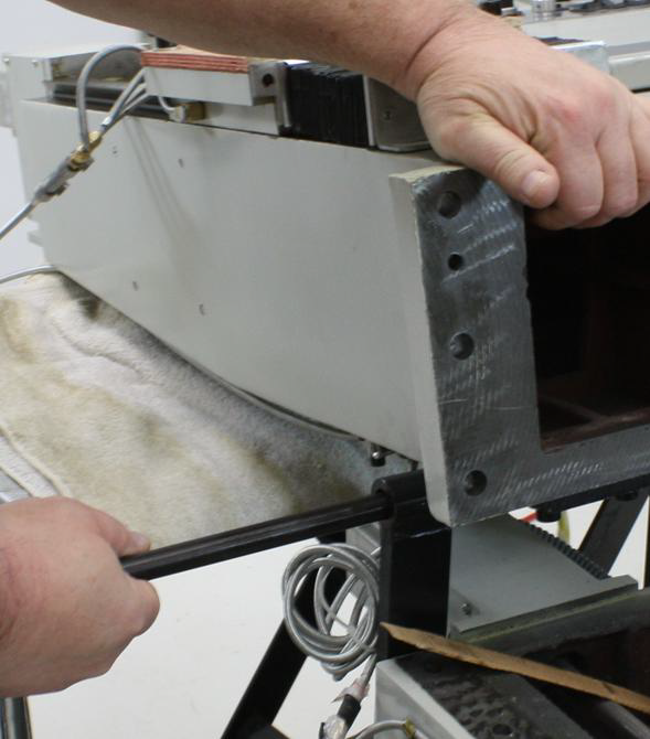
There are 2 taper pins used to align the Column to the Base, one on each side of the Column. These are to be removed in a similar manner described in section 2i. See Fig. 20. To ease pin removal and avoid damage to the pins, soak the pin area with quality penetrating oil for a couple of hours or so.
-
Remove the 6 mounting screws connecting the Column to the Base.
-
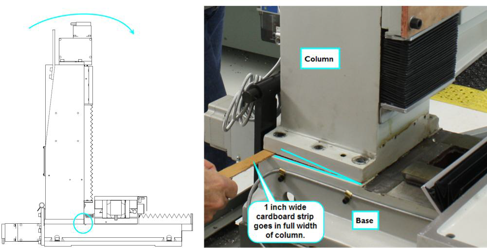
Cut a one inch wide, 10 inch long strip of corrugated cardboard.
-
Gently tilt the Column forward (the hinge pin will keep the Column from falling) and slip the cardboard strip in the gap created at the Column to Base interface. Note: it is better to use 2 people for this task. See Fig. 21.
-
Position a suitable stand or table behind the mill. If this is being done at ground level, then suitably sized timbers may be used. Using 2 people, gently tilt the Column backwards until it comes to a rest horizontally. See Fig. 22.
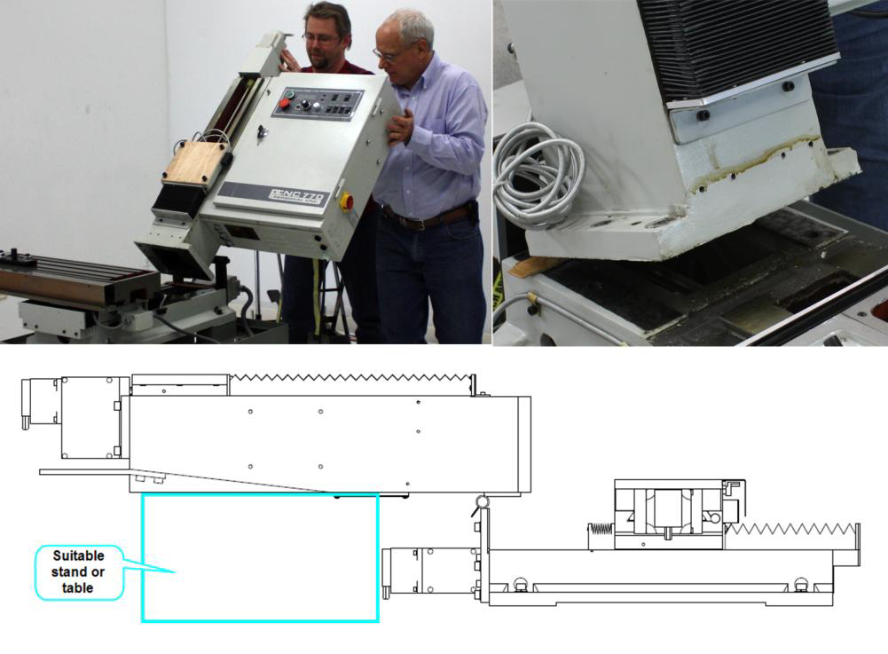
WARNING! THE COLUMN WEIGHS 255 POUNDS. Caution should be taken to avoid injury.
-
Remove the hinge pin cotter pin, and then the hinge pin itself. See Figure 23
-
The Column can now be separated from the Base.
IMPORTANT! Do not remove the hinge pieces until after reassembly. -
Using the fasteners indicated; mount the wooden protective covers to the critical surfaces. See Figure 24
Moving and Reassembly
For the most part reassembly is simply the reverse of the above steps, though there are a few exceptions and few important points to make. It is recommended to mount the Base to a suitable stand before re-assembly begins. It will be necessary to access all sides of the mill so reassembly must be completed prior to positioning the mill against a wall or corner.
Here are a few general tips to keep in mind during moving and reassembly.
-
Lifting - During lifting, always take care to affix lifting straps or chains to suitable anchors points. In general, sheet metal parts are not suitable for lifting, thought the electrical cabinet as a whole is an exception to this.
-
Surface Protection - Always take care to protect critical surface. Always use the wooden protective covers when moving major components. During mating of critical surfaces, avoid any point contact between surfaces (a corner of a casting contacting the face of a critical surface).
-
Surface Prep - Prior to mating critical surfaces, care should be taken to clean those surfaces from paint, dirt, metal chips or other debris. Do not use any tools that could scratch or mar the surface. Always apply a generous layer of oil (WD-40 works fine) to the surface prior to mating.
-
Installing taper pins - When installing taper pins, never apply excessive force. Pins should install most of the way by hand, and perhaps a slight tap with a small hammer to finish their seating.
-
Mounting Screws – Follow the tightening sequence instructions and torque to recommended levels. We suggest using anti-seize on the screw threads to prevent rusting during use.
Column Reassembly
Reassembly is, for the most part the reverse of the steps laid out above. Here is a list of a few items that deviate from this sequence or whose importance requires additional notes.
-
Prior to lifting the Column into place, be sure not to forget to use the cardboard strip as noted above in step 3i. This is important to prevent damage to critical surfaces during lifting.
-
Use the taper pins to establish alignment prior to installing mounting bolts. Take care to limit the amount of sliding motion between the critical surfaces during alignment.
-
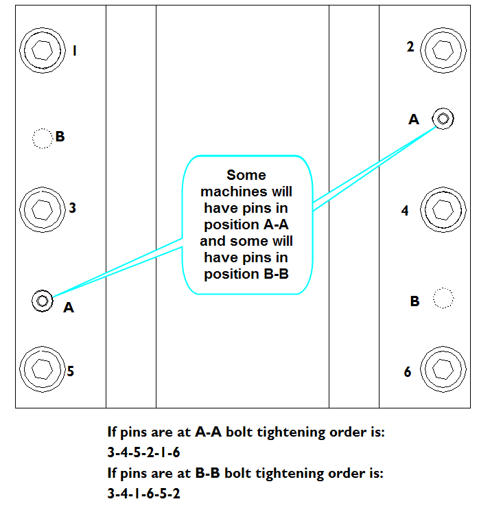
Follow Figure 25 below indicating the tightening sequence of the Column mounting screws. Torque to 74 Ft-lbs (100 Nm).
-
Be sure to follow the description in figure 17 to avoid connecting the wrong axis motor to the wrong connector.
Spindle Head Reassembly
-
Reassembly is, for the most part the reverse of the steps laid out above. Here is a list of a few items that deviate from this sequence or whose importance requires additional notes.
-
When sliding the spindle head over the fixture, be sure the fixture is not pushing up on the collet, this will collapse the collet making it impossible for it to fit over the fixture.
-
When preparing to connect the spindle head to the Column care should be taken not to damage the critical surfaces.
-
Alignment of the spindle head to the Column should be done as follows
-
Loosen the draw bar, this will allow a bit of play between the spindle and the fixture.
-
Move the mill bed such that there is about a ¼” gap between the mating surfaces. Visually align the components in the X direction (this does not have to be precise, but the closer the better).
-
Raise the Z axis about 1/8 inch above what would be the correct alignment height. This ensures that as the mounting screws are tightened, the spindle head is lifted up off the spindle fixture instead of driven down onto it.
-
It may be helpful to install 2 mounting screws in the top two holes hand tight to help carry the weight of the head as the alignment pins are worked in place.
-
Final alignment is a bit of a dance between pushing on the alignment pins, jogging the Y axis and holding up the weight of the head with the two mounting screws.
-
Final screw tightening should follow the sequence shown in figure 25 below. Final screw torque should be 41 Ft lbs (55Nm).
-
-
When connecting the spindle motor wires, be VERY SURE to connect the ground wire. If, when reassembly is completed, the spindle turns the wrong direction, simply switch any 2 of the 3 black power wires.
To view a PDF version of your manual, go to Tormach document TD10108.
If you have additional questions, we can help. Create a support ticket with Tormach Technical Support at tormach.com/how-to-submit-a-support-ticket for guidance on how to proceed.