Purpose
This document gives instructions on installing the Power Drawbar Foot Pedal Kit on a mill.
Product Information
Product: Power Drawbar Foot Pedal Kit (PN 31728)
|
Quantity |
Description |
|
1 |
Foot Pedal |
|
1 |
RJ11 Cable NOTE: This item is only used for PCNC mills. You may discard it if it's not used in the procedure for your specific machine. |
NOTE: If any items are missing, we can help. Create a support ticket with Tormach Technical Support at tormach.com/how-to-submit-a-support-ticket for guidance on how to proceed.
Before You Begin
-
770M/MX, 1100M/MX, and PCNC 440 Mills Require ATC If you're installing the Power Drawbar Foot Pedal Kit on an M or MX mill or a PCNC 440, you must have an Automatic Tool Changer (ATC). If you haven't yet done so, install the ATC now.
Install the Power Drawbar Foot Pedal Kit
The installation procedure varies based on your machine model.
770M/MX and 1100M/MX Mills
NOTE: This section also applies to M-style Automatic Tool Changers that you've installed on a PCNC mill. Part numbers for those ATCs include PN 39008 and PN 39009.
-
Put the foot pedal in the desired location (near the front of the machine).
-
Route the foot pedal cable around the back of the machine and toward the Automatic Tool Changer (ATC).
NOTICE! Don't route the foot pedal cable underneath the machine. If you do, it could interfere with the casters on the coolant tank, which may cause damage to the foot pedal cable. -
Find the gray foot pedal cable that's preinstalled on the ATC.
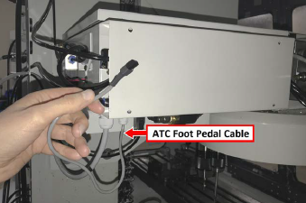
-
Connect the two-pin Molex connector from the foot pedal's cable to the mating connector on the ATC's cable.
-
Use cable ties to organize the cables.
PCNC 440 Mills
The installation procedure for using the Power Drawbar Foot Pedal Kit with a PCNC 440 varies by ATC serial number. Newer PCNC 440 ATCs have a preinstalled foot pedal cable, while older units require the use of the provided RJ11 cable.
Serial Number AH 111419 and Above
-
Put the foot pedal in the desired location (near the front of the machine).
-
Route the foot pedal cable around the back of the machine and toward the Automatic Tool Changer (ATC).
-
Find the gray foot pedal cable that's preinstalled on the ATC.
-
Connect the two-pin Molex connector from the foot pedal's cable to the mating connector on the ATC's cable.
-
Use cable ties to organize the cables.
Serial Number AH 111418 and Below
You must first remove the pre-installed cable on the foot pedal and replace it with the RJ-11 (phone) cable provided with this kit.
Complete the following steps in the order listed:
Make Electrical Connections
-
Remove the cover from the foot pedal. Then, set aside the screws and the cover.
-
Remove the spade connectors from inside the foot pedal. Then, loosen the cord grip and nut, and remove the entire cable from the foot pedal. You can discard this cable.
-
Find the RJ-11 cable (provided).
-
Put the end of the RJ-11 cable with exposed wires into the foot pedal.
-
Connect the brown wire from the cable to NO, and connect the white/brown wire from the cable to Common (as shown in the image).
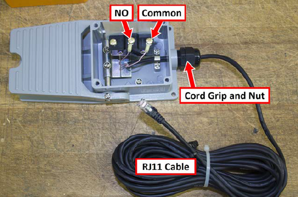
NOTE: Wire color and polarity don't matter.
-
Replace the cover on the foot pedal.
Install the Power Drawbar Foot Pedal
-
Put the foot pedal in the desired location (near the front of the machine).
-
Route the foot pedal cable around the back of the machine and toward the Automatic Tool Changer (ATC).
-
Remove the four screws securing the access plate to the rear of the ATC. Then, set aside the screws and the plate.
-
Cut the RJ-11 connector off of the foot pedal cable and strip the brown and white wires.
-
Insert the brown and white wires into the ATC control board's PEDL terminals as shown in the following image (see note below).
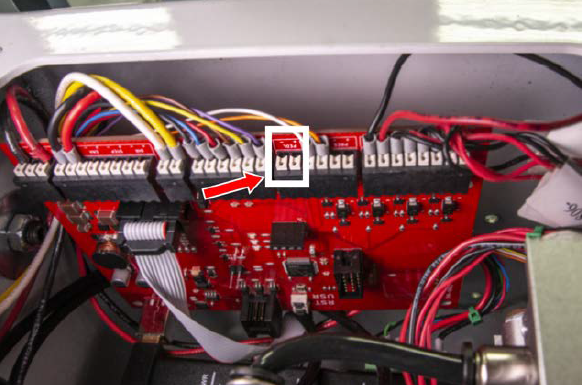
NOTE: Polarity doesn't matter, and there's no specific wire order required for this connection.
-
Replace the access plate on the rear of the ATC.
-
Use cable ties to organize the cables.
PCNC 1100 or PCNC 770 Mills
You must first remove the pre-installed cable on the foot pedal and replace it with the RJ-11 (phone) cable provided with this kit.
Complete the following steps in the order listed:
Make Electrical Connections
-
Remove the cover from the foot pedal. Then, set aside the screws and the cover.
-
Remove the spade connectors from inside the foot pedal. Then, loosen the cord grip and nut, and remove the entire cable from the foot pedal. You can discard this cable.
-
Find the RJ-11 cable (provided).
-
Put the end of the RJ-11 cable with exposed wires into the foot pedal.
-
Connect the brown wire from the cable to NO, and connect the white/brown wire from the cable to Common (as shown in the image).
NOTE: Wire color and polarity don't matter.
-
Replace the cover on the foot pedal.
Install the Power Drawbar Foot Pedal
-
Put the foot pedal in the desired location (near the front of the machine).
-
Route the foot pedal cable around the back of the machine and up through the energy chain.
NOTICE! Don't route the foot pedal cable underneath the machine. If you do, it could interfere with the casters on the coolant tank, which may cause damage to the foot pedal cable.
-
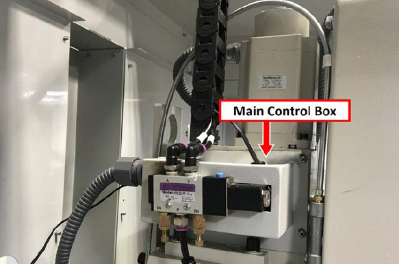
Remove the four screws on the corners of power drawbar's main control box that secure it to the Z-axis motor mount. Then, set aside the screws.
-
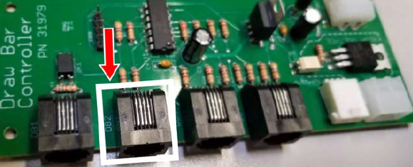
Connect the RJ-11 connector from the foot pedal's cable to the DB2 port on the power drawbar control board.
-
Replace the power drawbar's main control box on the Z-axis motor mount.
-
Use cable ties to organize the cables.
To view a PDF version of your manual, go to Tormach document TD10754.
If you have additional questions, we can help. Create a support ticket with Tormach Technical Support at tormach.com/how-to-submit-a-support-ticket for guidance on how to proceed.