NOTE: This manual is specifically for the PCNC 1100, but the process is much the same for the 1100M.
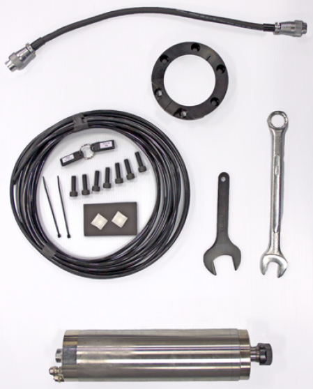
Product Identification: High-speed Spindle Kit (PN 35178)
Purpose: The purpose of this document is to detail installation, setup, use, and maintenance of the High-speed Spindle Kit on the PCNC 1100 mill.
IMPORTANT! Install required Motor Quick Change Kit (PN 35167) prior to High-speed Spindle Kit installation.
IMPORTANT! If a Power Drawbar is installed on mill, the pneumatic cylinder stack must be removed prior to High-speed Spindle Kit installation.
|
Qty |
High-speed Spindle Kit (PN 35178) |
PN |
|
1 |
High-speed Spindle |
34829 |
|
1 |
Clamping Collar |
33160 |
|
1 |
Spindle Cable |
35174 |
|
1 |
VFD Programming Stick (R8) |
31096 |
|
1 |
VFD Programming Stick (HSS) |
35177 |
|
7 |
M8x25 mm Socket Head Cap Screws |
34635 |
|
2 |
Cable Tie Holders |
33193 |
|
2 |
Cable Ties |
31719 |
|
1 |
30 mm Wrench (use w/ ER collet nut) |
30151 |
|
1 |
21 mm Wrench (use w/ ER collet nut) |
35523 |
|
16’ |
Nylon Tubing |
35463 |
Required Tools
-
Diagonal Cutters
-
Large Gear Puller (light duty)
-
M4 Hex Wrench
-
M5 Hex Wrench
-
M6 Hex wrench
-
M14 Wrench
-
Pin Spanner Wrench
-
Pliers
-
Phillips Screwdriver
-
Scotch-Brite (or similar)
-
WD-40® (or similar)
Performance Expectations
The High-speed Spindle is rated for continuous operation at 24,000 RPM, and can deliver up to 1.5 hp of power to the tool. The recommended operating speed range is between 10,000 RPM and 24,000 RPM. Commanded speeds as low as 1000 RPM are allowed to facilitate use of wiggler-style edge finders. Spindle power diminishes significantly at lower spindle speeds, so speeds should be kept as high as practical for a given cut.
High-speed Spindle Specifications
|
Speed |
24,000 RPM continuous |
|
Power |
1.5 hp water-cooled AC induction motor |
|
Diameter |
3.15” (80 mm) |
|
Length |
14” (356 mm) |
|
Weight |
20 lbs |
|
Tool Retention |
ER20 collets w/ dynamically balanced collet nut |
|
Coolant Compatible |
Yes |
Optimum performance is achieved when using small-diameter, carbide-cutting tools with coatings appropriate for the specific workpiece material. Typical applications include:
-
General purpose machining of aluminum, brass, plastic, wood, and other materials that benefit from high surface speeds
-
Surface contouring with a ball-end mill for mold making applications
-
Engraving
IMPORTANT! Active cooling is required to prevent overheating during prolonged, heavy-cutting operations. To cool the spindle, water must pass through spindle’s cooling jacket. Use the Water Chiller Kit (PN 35175) or similar for this purpose.
IMPORTANT! The High-speed Spindle’s labyrinth seal relies on spindle rotation to exclude coolant from spindle internals. Ensure spindle is spinning before coolant is turned on, and coolant is turned off before spindle is stopped.
R8 Spindle Removal
NOTE: Retain all R8 Spindle assembly parts removed in this procedure for future re-install.
-
Jog spindle nose to within 6” of machine table.
-
Power off mill according to “Power Off/On Procedure”.
WARNING! Electrical Shock Hazard: Be sure to power off machine before making any electrical modifications. Failure to do so may result in serious injury or death.
|
Power Off/On Procedure |
||
|
Power Off |
|
|
|
||
|
||
|
Power On |
|

|
|
||
|
||
|
||
-
Remove all tooling, fixtures, workpieces, and/or parts from mill so nothing impedes lowering of spindle.
-
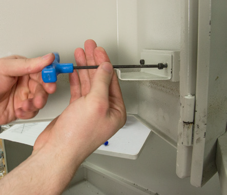
Using an M4 hex wrench, remove the spindle door Interlock Tab (see Figure 1); set aside for later use.
-
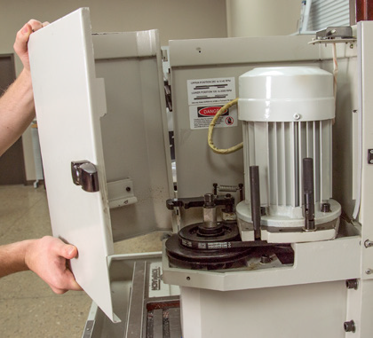
Remove Door (see Figure 2).
-
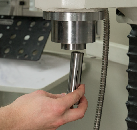
Remove Tormach Tooling System (TTS) collet or tool holder from R8 Spindle (see Figure 3).
-
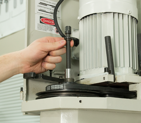
Unscrew and remove Drawbar and Thrust Washer from R8 Spindle (see Figure 4); set aside for future use.
-
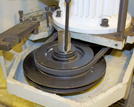
Using a Phillips screwdriver, loosen the Locking Screw on the pulley retention nut (see Figure 5).
-
With the Spindle Lock in place, use a pin spanner wrench or channel lock pliers to loosen pulley retention nut (see Figure 6).
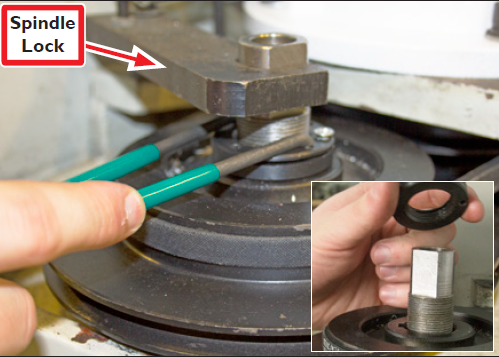
-
Move Spindle Lock to side; remove pulley retention nut (see Figure 6 inset); set aside for future use.
-
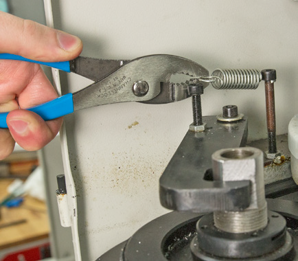
Using a pliers, carefully remove spring from the Spindle Lock (see Figure 7); set aside for future use.
-
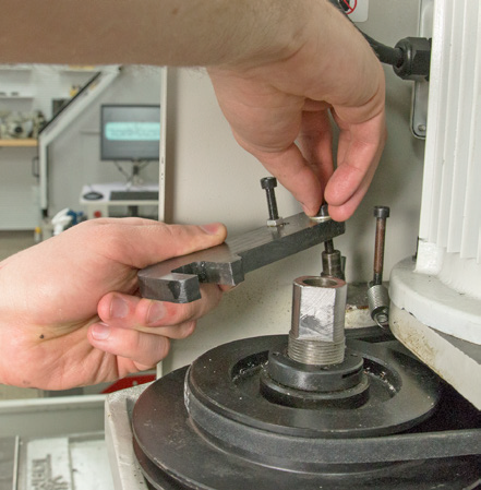
Using an M5 hex wrench, remove one socket head cap screw attaching Spindle Lock and Standoff to mill (see Figure 8); set aside for future use.
-
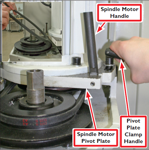
Loosen Pivot Plate Clamp Handle as shown in Figure 9. Swing Spindle Motor Handle down and move Spindle Motor Pivot Plate forward to remove spindle belt (see Figure 9 inset).
-
Swing Spindle Motor Pivot Plate back to allow spindle belt removal; set aside belt for future use.
-
Hand tighten Pivot Plate Clamp Handle.
-
Power off machine according to “Power Off/ On Procedure” earlier in this document.
-
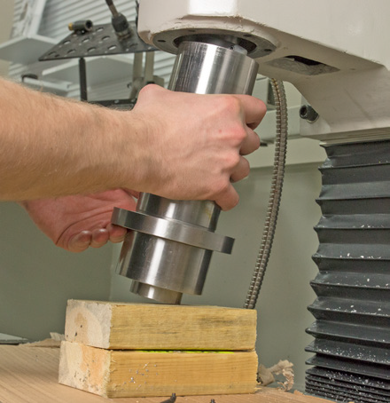
Place wood block(s) under R8 Spindle to prevent damage to both spindle and machine table; lower spindle until gentle contact is made with block(s) as shown in Figure 10.
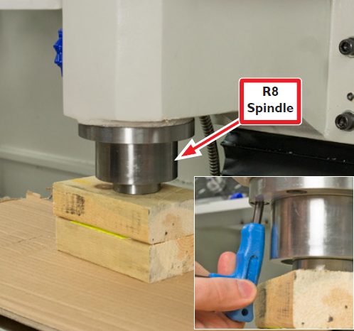
NOTE: Allow enough space between table and R8 Spindle to allow access to six socket head cap screws (see Figure 10 inset).
-
Using an M6 hex wrench, remove six socket head cap screws; set aside for future use.
-
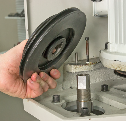
Slowly jog machine up to raise Head Casting just until Spindle Pulley can be removed (see Figure 11); set aside for future use.
NOTE: If pulley is stuck, spray with WD-40® and/or use large gear puller.
-
Carefully raise Head Casting slowly until R8 Spindle can be removed (see Figure 12); set aside for future use.
High-speed Spindle Installation
-
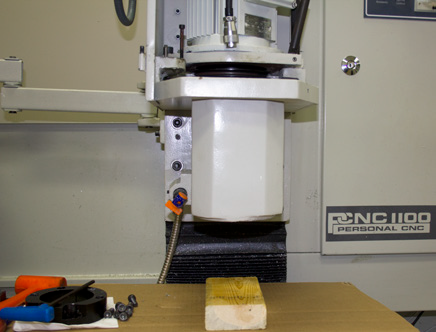
Jog machine down to position spindle mounting face approximately 8” off of machine table (see Figure 13).
-
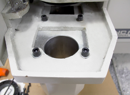
Thoroughly clean spindle bore and use WD-40® or similar to lightly lubricate.
NOTE: Inside rim of Spindle Bore should be free of paint and corrosion. If necessary, use a mild abrasive material such as Scotch-Brite™ to remove any paint overspray present (see Figure 14).
CAUTION! Crush Hazard: Keep hands clear below Spindle Bore when lowering High-speed Spindle into bore. Failure to do so could result in serious injury and/or machine damage.
CAUTION! Pinch Hazard: Keep hands clear on sides of Spindle Bore when lowering High-speed Spindle into bore. Failure to do so could result in serious injury and/or machine damage.
-
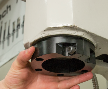
Loosely attach Clamping Collar to Head Casting with two M8x25 mm Socket Head Cap Screws (included), one each on opposite sides of collar for support (see Figure 15).
-
Loosely install one M8x25 mm Socket Head Cap Screw in clamp position of Clamping Collar (see Figure 16).
-
Ensure exterior of High-speed spindle is clean.
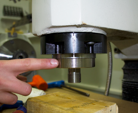
IMPORTANT! Position wood block under Head Casting to protect table against inadvertent drops.
-
Using two hands, carefully lower High-speed Spindle through bore. Take care to prevent spindle from falling through bore onto machine table (see Figure 17).
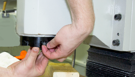
NOTE: Depending on fit, Clamping Collar may prevent High-speed Spindle pass through. If necessary use flat screwdriver to wedge Clamping Collar open at slit. Ensure two mounting screws previously installed are not preventing Clamping Collar from flexing.
-
Adjust spindle depth in collar until between 5/8” to 3/4” of spindle is exposed beyond bottom of Clamping Collar as shown in Figure 18.
-
Using a hex wrench, finish installing Clamping Collar with four remaining M8x25 mm Socket Head Cap Screws (included) as shown in Figure 19. Tighten all six securely.
Cooling System Connections
NOTE: The High-speed Spindle requires a source of cooling water. Use of a device such as Water Chiller Kit (PN 35175) or similar is required to circulate water through High-speed Spindle.
-
Using a diagonal cutters, cut 16’ Nylon Tubing (included) in half to create two equal-lengths.
-
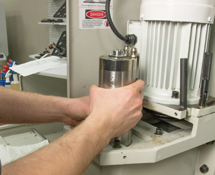
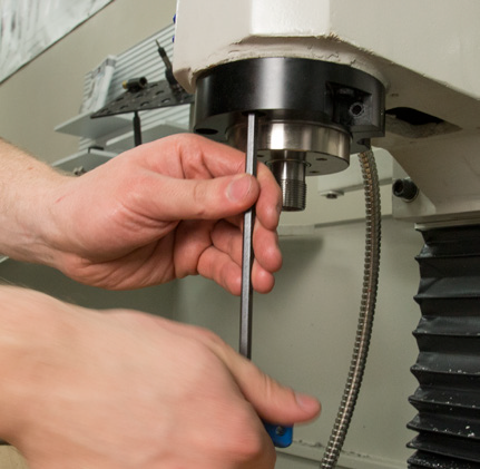
Using an M14 wrench, remove one Compression Fitting from top of High-speed Spindle (see Figure 20).
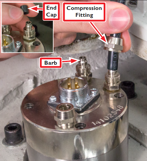
-
Remove plastic End Cap on Barb under Compression Fitting (see Figure 20 inset).
-
Slide one end of water line through Compression Fitting and push forcefully onto Barb; tighten nut and repeat procedure for second water line.
-
Route water lines from High-speed Spindle over back of mill.
-
Raise Machine Column to maximum height and then secure water lines with two Cable Tie Holders and Cable Ties (included) in locations shown in Figure 21.
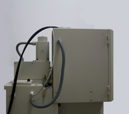
NOTE: Attaching water lines to mill with Machine Column at maximum height helps prevent pinching and disconnection.
-
Attach loose ends of water lines to Water Chiller’s inlet and outlet connections (see Figure 22).
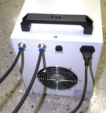
NOTE: There is no designated supply or return water line.
-
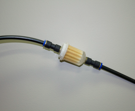
Using a diagonal cutters, cut chiller inlet line to install Water Chiller Replacement Filter (PN 35495) or similar. Arrow in Figure 23 indicates direction of water flow from spindle to inlet connection.
-
Fill chiller with 2.25 gallons of water and add Water Chiller Anti-corrosive Additive (PN 35553) or similar according to product directions.
-
Plug chiller into 115 VAC; turn on chiller to inspect for leaks.
Electrical Connections
-
Power off machine according to “Power Off/ On Procedure” earlier in this document.
-
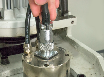
Connect one end of Spindle Cable (included) to spindle motor; screw down threaded connector (see Figure 24).
-
Connect loose end of Spindle Cable to Quick-disconnect Junction Box and screw down threaded connector (see Figure 25).
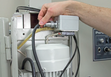
NOTE: The above step assumes the required Motor Quick Change Kit (PN 35167) is already installed.
VFD Programming
-
Power off machine according to “Power Off/ On Procedure” earlier in this document.
IMPORTANT! Ensure mill is off before inserting VFD Programming Stick.
-
Insert included VFD Programming Stick (HSS) into VFD with gold contacts on left as shown in Figure 26.
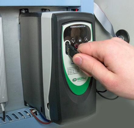
NOTE: Two different VFD programming sticks are included with High-speed Spindle Kit, one to convert mill for High-speed Spindle use, and a second to revert mill back to R8 Spindle use.
-
Leave VFD Programming Stick (HSS) plugged into VFD.
Software Configuration
-
Power on mill according to “Power Off/ On Procedure” earlier in this document.
-
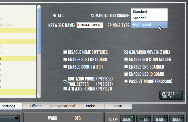
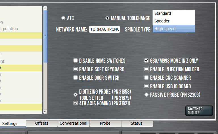
In PathPilot interface, click on Settings screen tab (see Figure 27).
-
In Spindle Type drop-down menu, select High-speed.
-
On Settings screen, verify Manual Tool Change is selected (see Figure 27).
Spindle Break-in (required)
IMPORTANT! Adhere to Spindle Break-in procedures. Failure to do so may result in premature wear or failure.
Break-in High-speed Spindle prior to first use as follows:
-
Turn on Water Chiller (PN 35175) or other water supply device
-
Run spindle at 6000 RPM for 1 hour
-
Run spindle at 12,000 RPM for 1 hour
-
Run spindle at 18,000 RPM for 1 hour
-
Run spindle at 24,000 RPM for 1 hour
IMPORTANT! The above break-in procedures should be run consecutively.
To maximize the length of the High-speed Spindle’s operational service, warm it up daily before starting machining operations; turn on water chiller (or similar device). Run the spindle at 8000 RPM, 16,000 RPM, and 24,000 RPM for four minutes in each range. This allows spindle to attain nominal operating temperature and ensures optimum spindle performance.
NOTE: If the spindle is not used for more than one month, run the spindle at 8000 RPM, 16,000 RPM, and 24,000 RPM for 30 minutes in each range.
Cutting Tool Retention
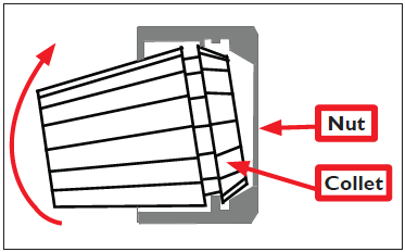
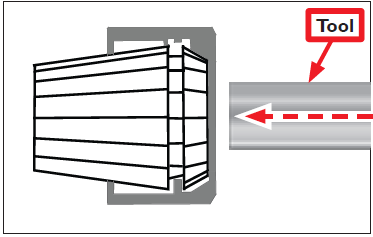
The ER20 collet is a self-extracting collet. The collet must first be mounted in the nut before a cutting tool can be installed:
-
Holding collet at an angle (see Figure 28), tip collet to snap it into place as shown in Figure 29.
-
Insert assembly into spindle and tool into collet; tighten using 21 mm and 30 mm wrenches (included).
IMPORTANT! If above steps are not followed, collet/nut may be damaged and holding capacity reduced.
NOTE: Collet nut is intentionally bored asymmetrical. This allows collet to self extract as the nut is loosened.
Reverting to R8 Spindle
To revert the mill back to the R8 Spindle, reverse all instructions detailed in this document.
-
Power off mill according to “Power Off/ On Procedure” earlier in this document.
IMPORTANT! Ensure mill is powered off before inserting VFD Programming Stick.
-
Complete procedure by reinstalling VFD Programming Stick (R8) into VFD; power on mill.
-
On the Settings screen select Standard spindle (see Figure 30).
Load Meter Use (PCNC Machines Only)
Tormach recommends the use of a spindle load meter when developing tool paths for use with the High-speed Spindle. The spindle load meter allows the operator to adjust cutting feeds and speeds in response to cutting loads, preventing tool breakage or the overloading of the spindle drive. Available load meters include:
-
Load Meter (PN 32096) - Panel-mounted for PCNC 1100 Series 3 mills
-
Load Meter (PN 31101) - Top-mounted for PCNC 1100 (Series II) and PCNC 770 (all models)
-
To view a PDF version of your manual, go to Tormach document TD10368.
If you have additional questions, we can help. Create a support ticket with Tormach Technical Support at tormach.com/how-to-submit-a-support-ticket for guidance on how to proceed.