Product Identification
15L Slant-PRO Lathe Enclosure Kit (PN 34713)
Purpose
The purpose of this document is to guide you through assembly and installation of the 15L Slant-PRO Lathe enclosure. There are four sections to this installation: “Enclosure Kit Parts”, “Enclosure Assembly”, “Enclosure Installation”, and “Limit Switch Trigger Plate Installation and Limit Switch Adjustment”.
WARNING! Transport and Lift Hazard: The transport, lifting, and moving of lathe enclosure should be done by qualified professionals. Failure to do so may result in machine damage, serious injury or death.
IMPORTANT: If using a turret, it must be installed prior to installing the lathe enclosure kit.
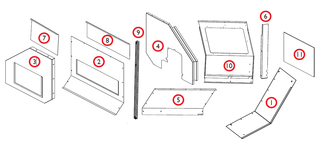
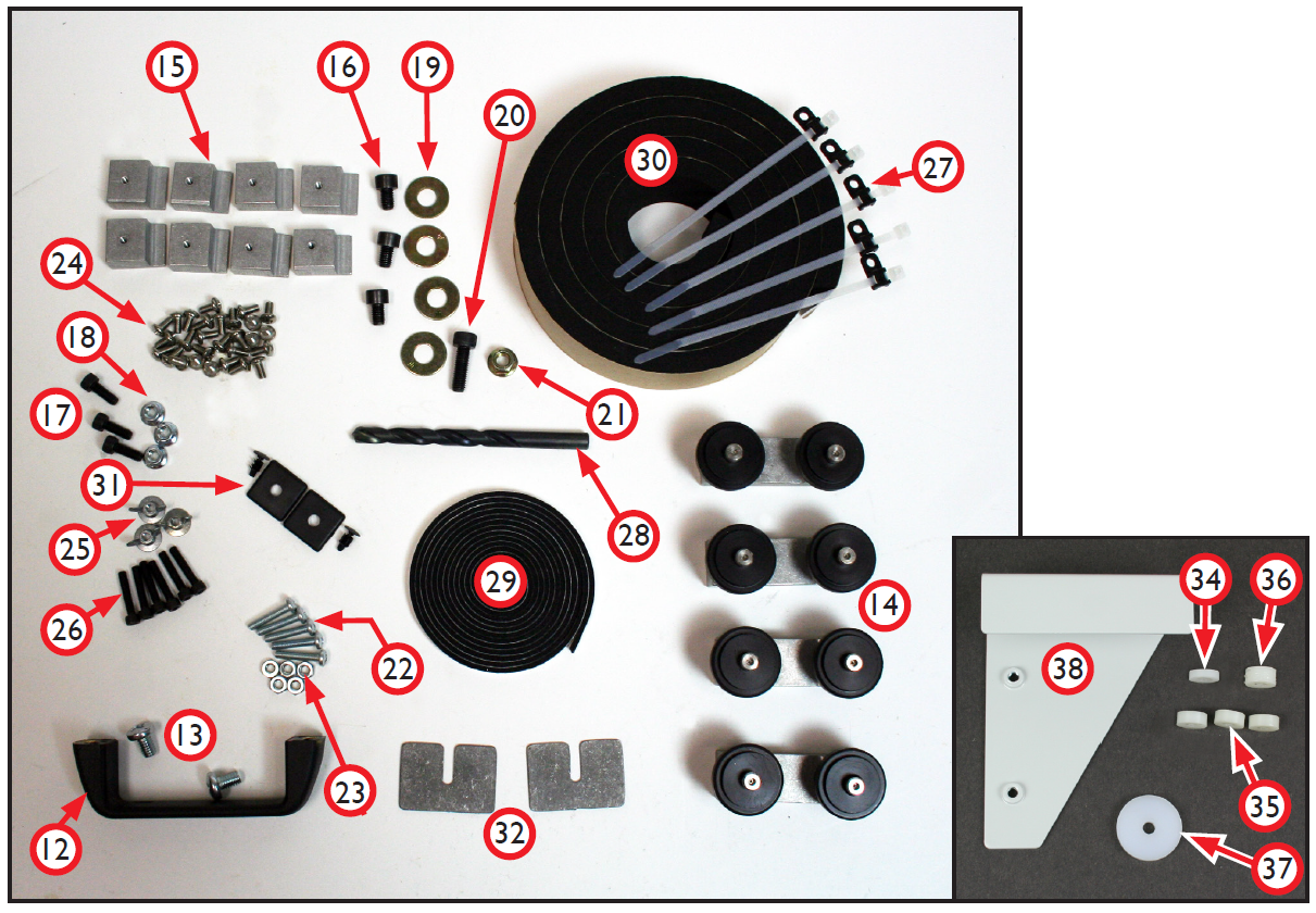
Enclosure Kit Parts
Review enclosure kit contents before starting installation:
|
Item# |
Lathe Enclosure Kit (PN 34713) |
Qty |
|
1 |
Front Right Panel |
1 |
|
2 |
Rear Panel |
1 |
|
3 |
Right Side Panel |
1 |
|
4 |
Left Side Panel |
1 |
|
5 |
Top Panel |
1 |
|
6 |
Drip Tray |
1 |
|
7 |
Right Access Panel |
1 |
|
8 |
Rear Access Panel |
1 |
|
9 |
Door Rail |
2 |
|
10 |
Door |
1 |
|
11 |
Door Window |
1 |
|
12 |
Door Handle |
1 |
|
13 |
5/16” × 3/4” Pan Head Screws (Door Handle) |
2 |
|
14 |
Door Roller Brackets |
4 |
|
15 |
Door Window Clips |
8 |
|
16 |
M8 × 12 mm Socket Head Cap Screws |
3 |
|
17 |
M6 × 16 mm Socket Head Cap Screws |
3 |
|
18 |
M6 Flange Nuts |
3 |
|
19 |
M8 Flat Washers |
4 |
|
20 |
M8 × 25 mm Socket Head Cap Screw |
1 |
|
21 |
M8 Flange Nut |
1 |
|
22 |
10-32 × 1” Pan Head Screws |
5 |
|
23 |
10-32 Hex Nuts |
5 |
|
24 |
10-32 × 3/8” Pan Head Screws |
35 |
|
25 |
10-32 Flange Nuts |
3 |
|
26 |
10-32 x 1.5” Socket Head Cap Screws |
6 |
|
27 |
Wire Tie Holders and Ties |
5 |
|
28 |
3/8” Drill |
1 |
|
29 |
1/4” Foam Gasket Tape |
7’ |
|
30 |
1.5” x 1/4” Thick Foam Tape |
75” |
|
31 |
Plastic End Caps w/ Lock Screws |
2 |
|
32 |
Shims |
2 |
|
33 |
1.5” x 1/2” Thick Foam Tape (not shown) |
6” |
|
34 |
Door Rail Spacer 1/2” x 1/8” |
1 |
|
35 |
Door Rail Spacer 1/2” x 3/16” |
3 |
|
36 |
Door Rail Spacer 1/2” x 1/4” |
1 |
|
37 |
Door Rail Spacer 1” x 1/8” |
1 |
|
38 |
Limit Switch Trigger Plate |
1 |
Required Tools
-
Phillips Screwdriver
-
Drill
-
Metric Hex Wrench Set
-
3/8” Wrench
-
Hammer
-
Center Punch
-
Razor Blade
Enclosure Assembly
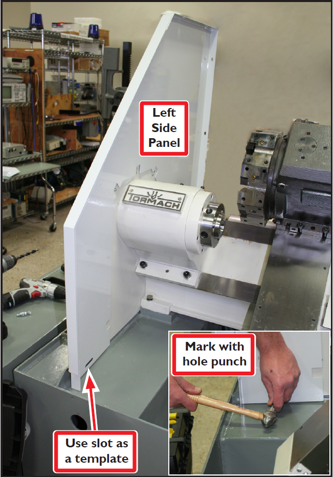
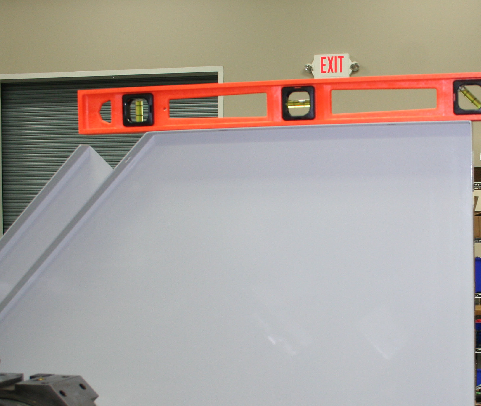
The Left Side Panel has a slot in the lower left corner which is used to fasten this corner to the lathe. Use the slot as a template to mark the location to drill the fastener hole as follows:
-
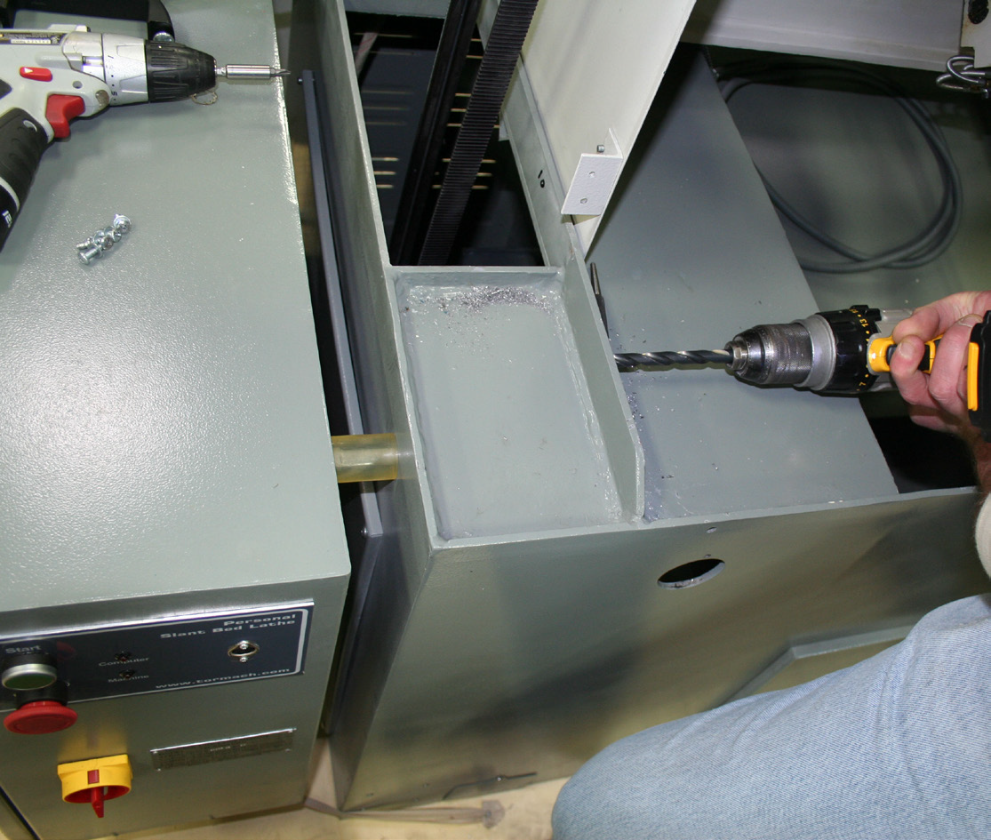
Using Left Side Panel as a template, temporarily place it on lathe as shown in Figure 1. Hold it in place by loosely attaching panel’s back corner to lathe using one M8 × 12 mm Socket Head Cap Screw. Using a level, confirm panel is level (see Figure 2). Mark a drill hole through slot with a hole punch as shown in Figure 1 inset. Using the (included) 3/8” Drill, drill a hole through the lathe casting (see Figure 3). Remove panel for installation later.
NOTE: Lathe enclosure should be assembled on the floor.
-
Slide the Rear Panel into the inside lip of the Right Side Panel; secure with four 10-32 × 3/8” Pan Head Screws (see Figure 4).
-
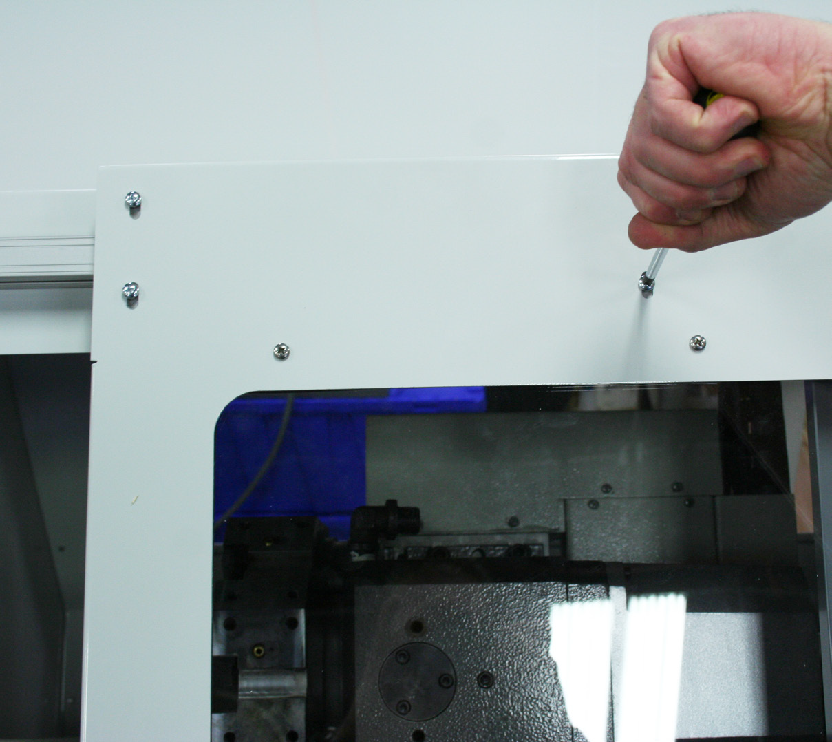
Slide the Top Panel under the lip of the Right Side Panel and against the Rear Panel; secure with five 10-32 × 3/8” Pan Head Screws (see Figure 5).
-
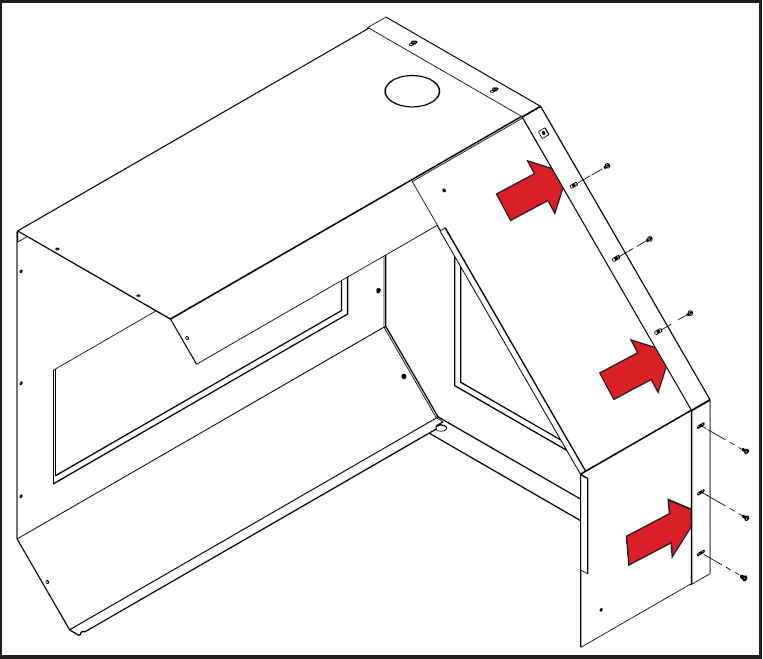
Slide the Front Right Panel under the lip of the Right Side Panel and over the Top Panel; secure with six 10-32 × 3/8” Pan Head Screws (see Figure 6).
-
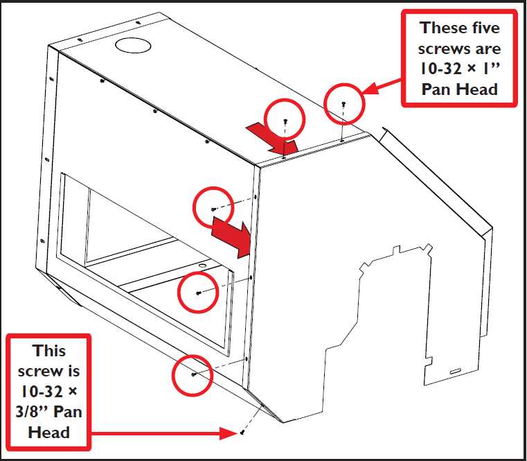
Slide the Left Side Panel over the edge of the assembly; secure using five 10-32 × 1” Pan Head Screws and one 10-32 × 3/8” Pan Head Screw as shown in Figure 7.
-
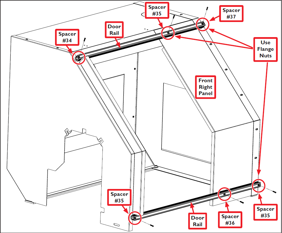
Secure each of the two Door Rails to the top and bottom of the enclosure with three 10-32 x 1.5” Socket Head Cap Screws (see Figure 8). Insert Door Rail Spacers between each Door Rail and enclosure for support (see Figure 8). Three of the six Door Rail screws are fastened with 10-32 Flange Nuts as shown in Figure 8.
-
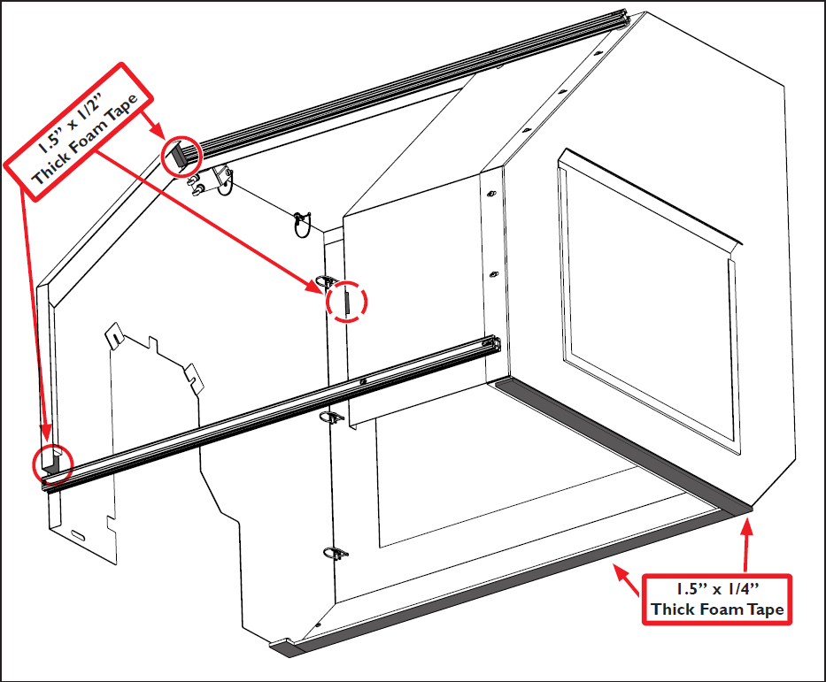
Measure, cut, and adhere 1.5” x 1/4” Thick Foam Tape to bottom of enclosure as shown in Figure 9.
-
Measure, cut, and adhere 1.5” x 1/2” Thick Foam Tape to door area as shown in Figure 9.
-
Measure, cut, and adhere 1.5” x 1/2” Thick Foam Tape to inside flange (not shown) of Front Right Panel (see Figure 9).
-
Measure, cut and adhere 1/4” Foam Gasket Tape to form a seal around the inside of the Door Window Opening; peel off backing and adhere to Door (see Figure 10).
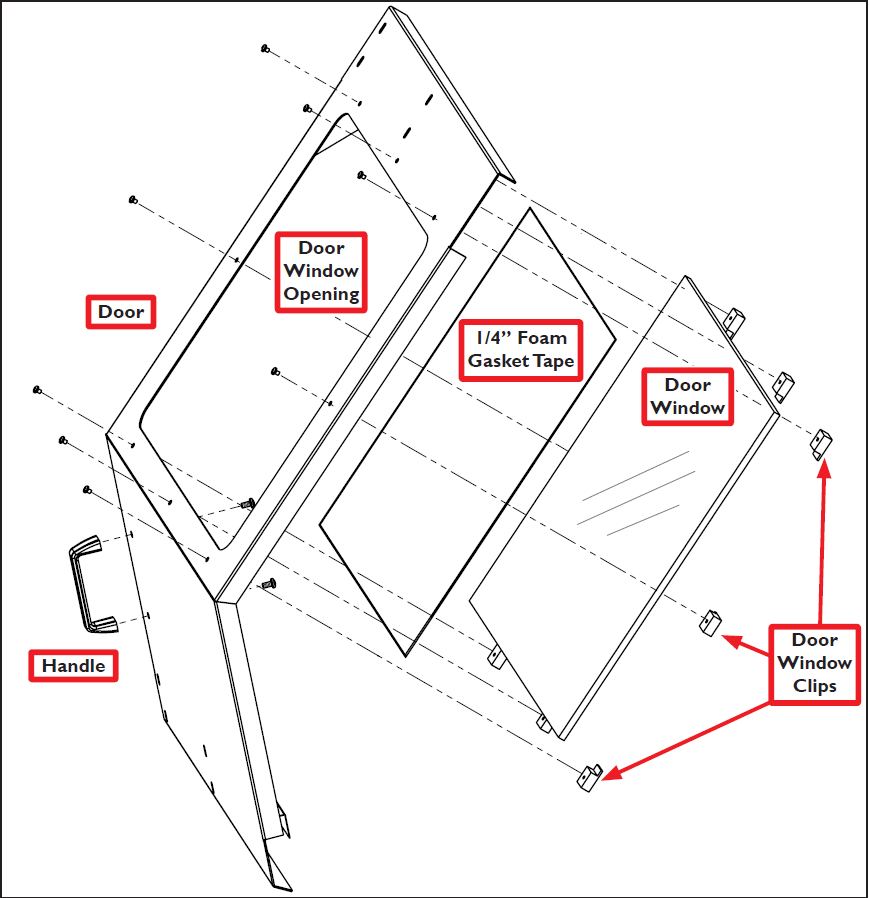
-
Attach Door Window to Door using eight Door Window Clips with eight 10-32 × 3/8” Pan Head Screws (see Figure 10); attach Door Handle using two 5/16” × 3/4” Pan Head Screws. Set door aside for later installation.
NOTE: Do not install the Limit Switch Trigger Plate at this time.
Enclosure Installation
-
Remove the lathe’s Half-moon Plate located next to the Rotary Encoder see Figure 11); set aside.
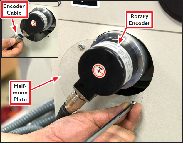
-
Unscrew and disconnect the Encoder Cable (see Figure 11 inset).
-
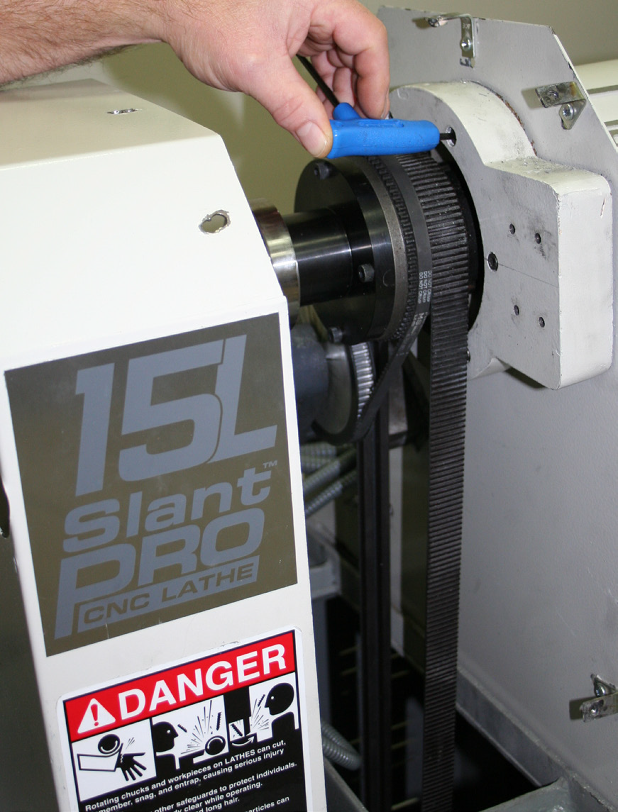
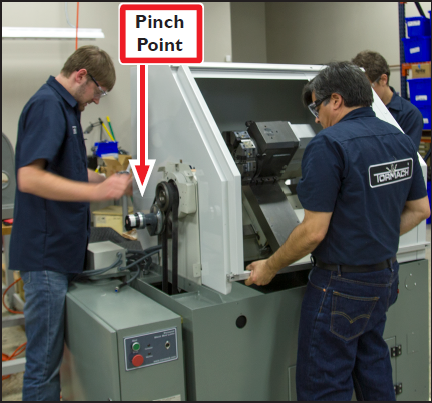
Loosen six Phillip’s head screws and remove the Spindle Belt Cover (see Figure 12); set aside.
-
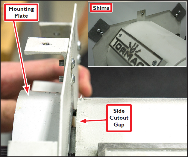
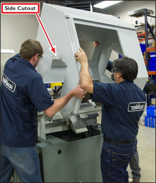
Loosen six socket head cap screws attaching Mounting Plate to headstock enough to create a Side Cutout Gap (see Figures 12 and 13).
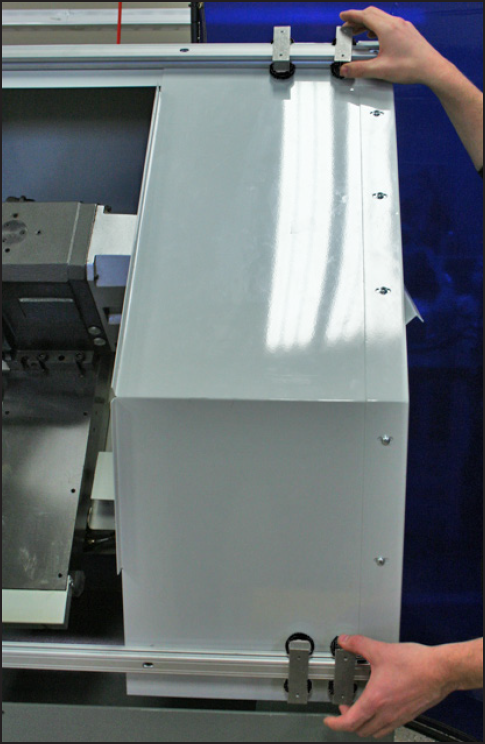
WARNING! Transport and Lift Hazard: The transport, lifting, and moving of lathe enclosure should be done by qualified professionals. Failure to do so may result in machine damage, serious injury or death.
-
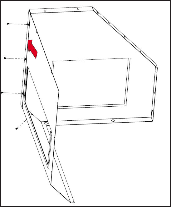
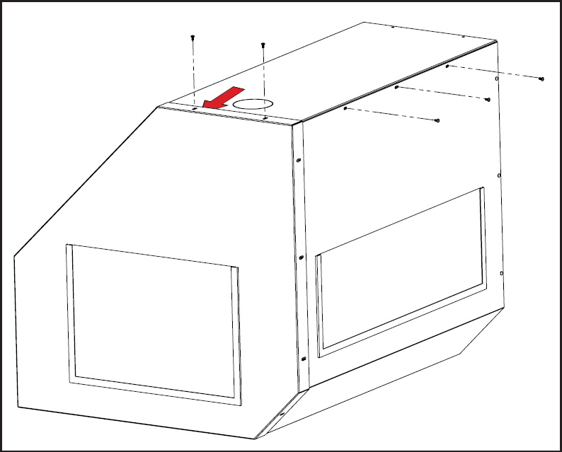
With Door not yet attached, carefully maneuver enclosure up and over lathe (see Figures 14 and 15); lower slowly ensuring the Side Cutout is inserted into the Side Cutout Gap shown in Figures 13, 14, and 15.
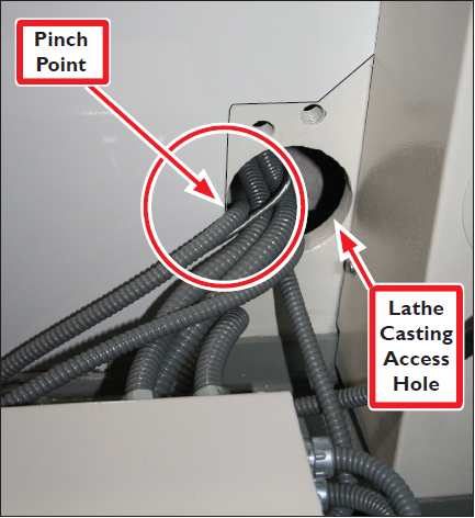
IMPORTANT: Make sure cables routed through Lathe Casting Access Hole do not get pinched (see Figure 16).
IMPORTANT: If necessary, Shims (included) can be used to snug Left Side Panel to Mounting Plate (see Figure 13 inset).
NOTE: Portions of the enclosure may need some fasteners loosened to allow for proper adjustment of and fitting to the lathe.
-
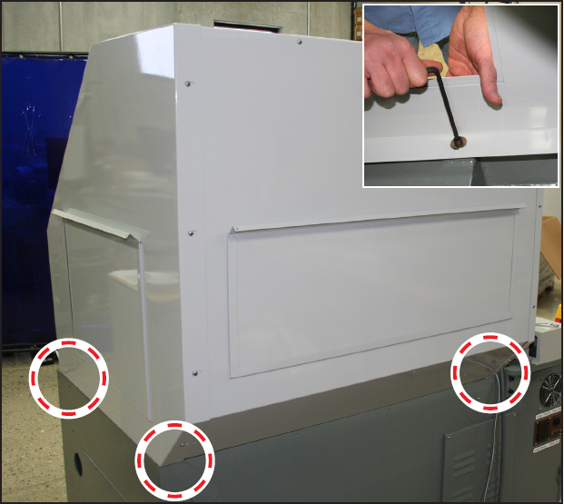
Attach each of the three internal corners of the enclosure shown in Figure 17 to the lathe casting with one M8 × 30 mm Socket Head Cap Screw and one M8 Flat Washer.
-
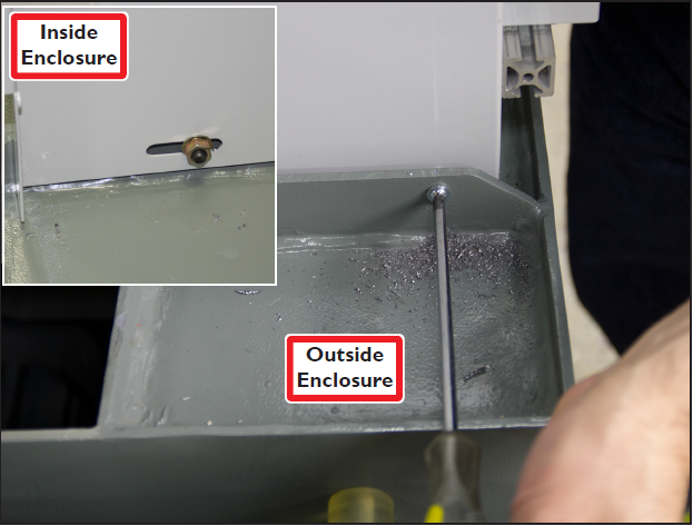
Attach the fourth enclosure corner (front left) via the 3/8” hole made in step 1 using one M8 × 25 mm Socket Head Cap Screw, one M8 Flange Nut, and one M8 Flat Washer (see Figure 18 and inset).
-
Slide two Door Roller Brackets onto both the top and bottom Door Rails as shown in Figure 19.
NOTE: Do not attach enclosure Door at this time.
-
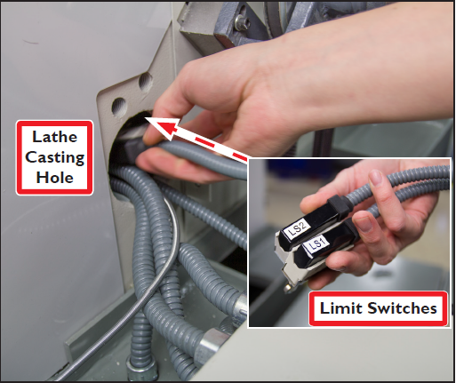
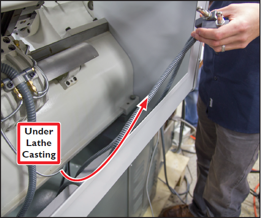
Locate two loose limit switches (LS1 and LS2 on lathe) and route them through Lathe Casting Hole and under Lathe Casting (see Figures 20 and 21).
-
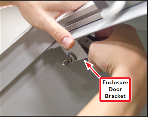
Continue to feed limit switch cables through enclosure from back to front; attach Limit Switches loosely to Enclosure Door Bracket for later adjustment (see Figure 22).
-
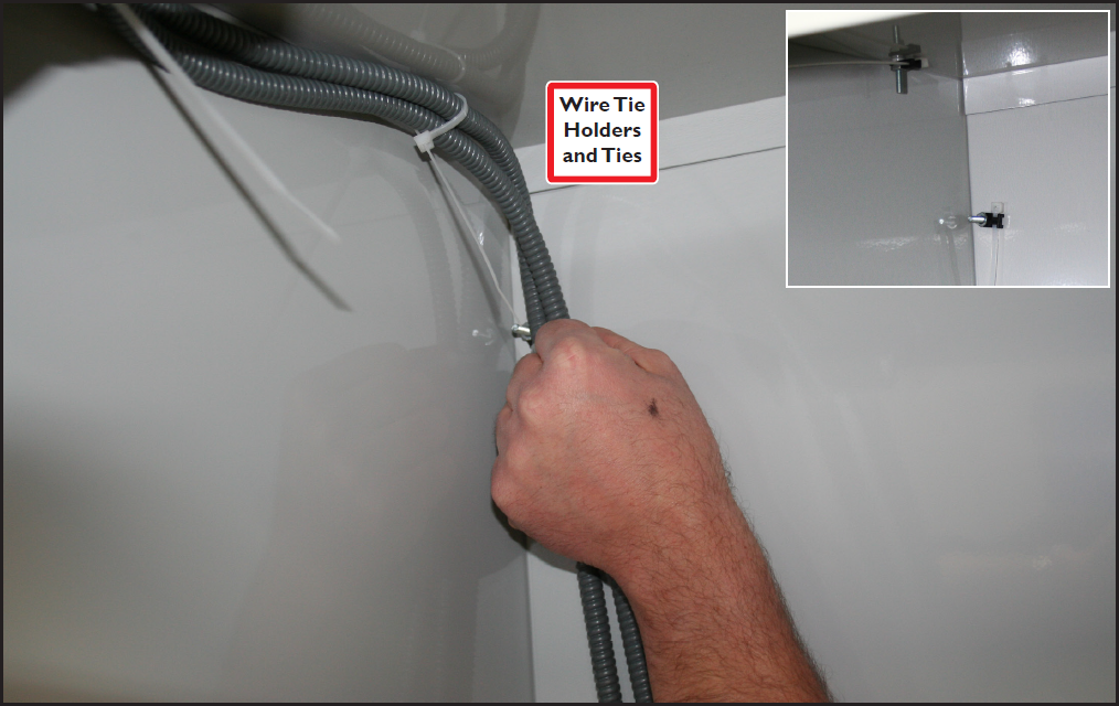
Attach five Wire Tie Holders and 2Ties to five 10-32 × 1” Pan Head Screws installed through the Back Panel in step 5 (see Figure 23 and inset); secure Limit Switch cables to ties.
-
Hang Door on Door Rails ensuring Door Roller Brackets are aligned on the top and bottom of Door.
-
Using eight 10-32 × 3/8” Pan Head Screws, loosely attach top and bottom of Door to two the respective Door Roller Brackets (see Figures 24 and 25). Adjust these eight screws as necessary to ensure smooth Door motion.
-
Install two Plastic End Caps w/ Lock Screws on the right ends of the Door Rails (see Figure 26).
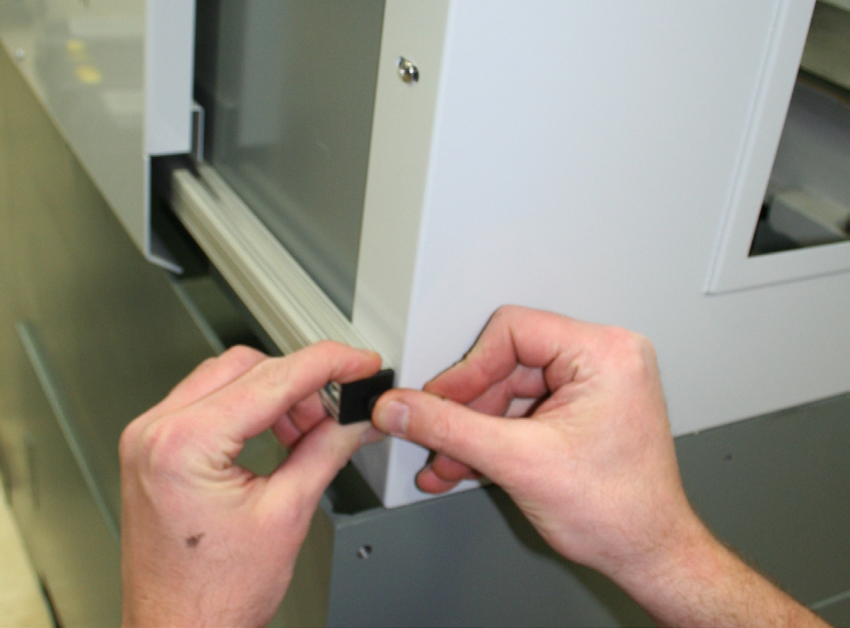
NOTE: Two Plastic End Caps on left end of Door Rails are pre-installed.
-
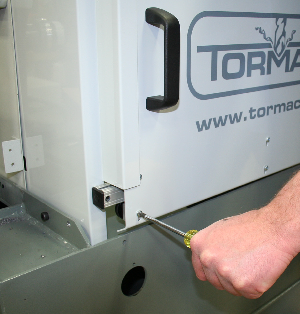
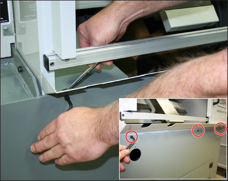
Attach the Drip Tray to the front of the lathe using three M6 × 16 mm Socket Head Cap Screws and M8 Flange Nuts (see Figure 27 and inset); tighten snugly.
-
Re-tighten six Mounting Plate bolts snugly (see Figure 12).
-
Re-attach Spindle Belt Cover using six Phillip’s head screws (see Figure 12).
-
Re-attach the Half-moon Plate next to the Rotary Encoder (see Figure 11).
-
Re-connect the Encoder Cable (see Figure 11 and inset).
Limit Switch Trigger Plate Installation and Limit Switch Adjustment
-
Open Door as shown in Figure 28. Using two 10-32 x 3/8” Screws, install Limit Switch Trigger Plate to Door (see Figure 28).
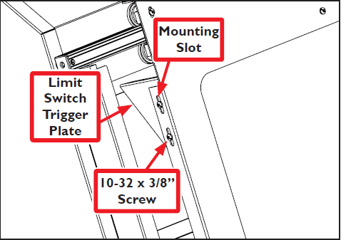
NOTE: Initially, position the Limit Switch Trigger Plate in the middle of the Mounting Slots to allow for adjustment (see Figure 28).
-
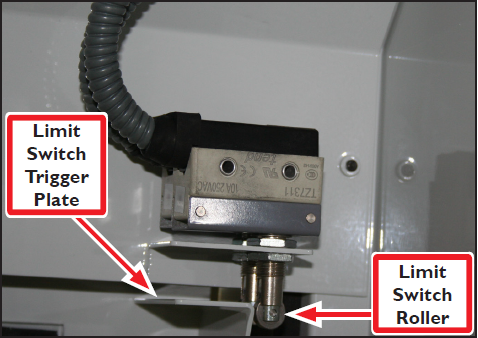
Assess the amount of Limit Switch adjustment required by carefully closing door until Limit Switch Rollers come in contact with Limit Switch Trigger Plate (see Figure 29).
NOTE: Viewing Limit Switches through the back access panel may make adjustment assessment easier.
-
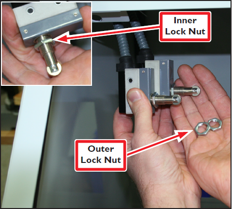
Adjust Limit Switch Roller height by removing Limit Switches from bracket and unscrewing Outer Lock Nut (see Figure 30).
-
Next, adjust Inner Lock Nut to desired height (see Figure 30 inset).
-
Reinstall one Limit Switch and check roller height by closing door. Adjust as needed; repeat for second Limit Switch.
-
Once correct height is determined, double check to ensure Limit Switches are engaging properly. If correctly adjusted, two clicks are heard as the rollers run across the Limit Switch Trigger Plate. If sound is not heard, adjust switch height accordingly.
-
Fine tune Limit Switch Trigger Plate height by loosening the screws and adjusting the plate up and down as necessary (see Figure 31).
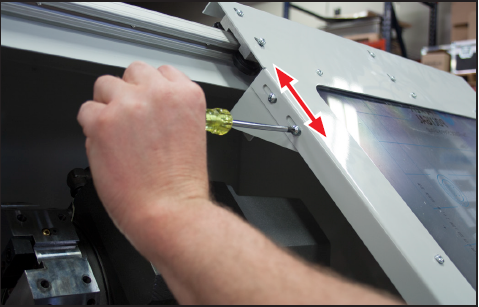
NOTE: The Limit Switch Trigger Plate should engage the Limit Switches enough so that the door will not open with a slight bump, but not so much that the Limit Switches are bottomed out in their travel.
To view a PDF version of your manual, go to Tormach document TD10315.
If you have additional questions, we can help. Create a support ticket with Tormach Technical Support at tormach.com/how-to-submit-a-support-ticket for guidance on how to proceed.