Purpose:
This document details installation of the lathe’s Chuck Guard Kit.
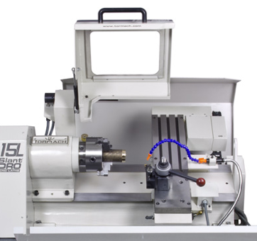
Product Identification: 15L Slant-PRO Lathe Chuck Guard Kit (PN 33323)
|
Qty |
Chuck Guard Installation Kit (PN 33323) |
|
1 |
Chuck Guard |
|
1 |
Back Splash |
|
1 |
Front Splash Guard |
|
4 |
Socket Head Cap Screws (5 mm) w/ lock washers |
|
2 |
Socket Head Cap Screws (6 mm short) w/ lock washers and nuts |
|
1 |
Splash Flap w/ two Metal Tie Down Strips |
|
1 |
T-hex Wrench (6 mm) |
|
10 |
M5 Phillips Head Screws, Nuts, and Lock Washers |
|
3 |
Socket Head Cap Screws (6 mm long) w/ Flat Washers, Lock Washers, and Nuts |
|
1 |
Strip of Edge Trim |
NOTE: If any of these items are missing, contact Tormach at (608) 849-8381 for a replacement.
NOTE: Some screws listed in this document are pre-installed on lathe.
Install Chuck Guard
-
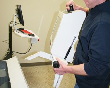
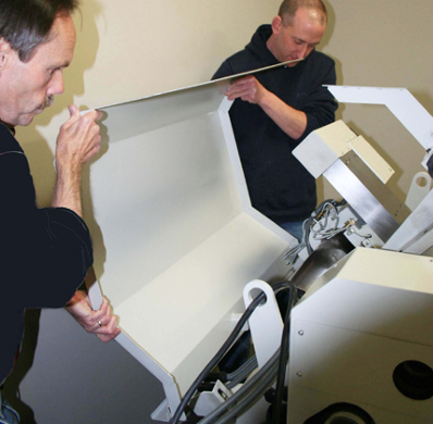
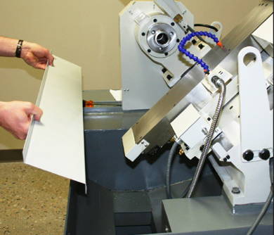
After unpacking the Chuck Guard, hold it with two hands in the locations shown in Figure 1.
-
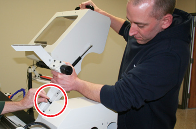
Hold the Chuck Guard arm in alignment with the headstock holes (see Figure 2).
NOTE: Installation of the Chuck Guard arm requires two people.
-
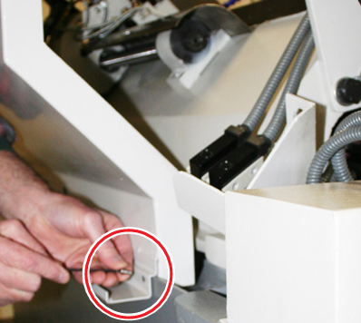
Using a hex wrench, tighten four socket head screws (pre-threaded) into headstock holes (see Figure 3).
-
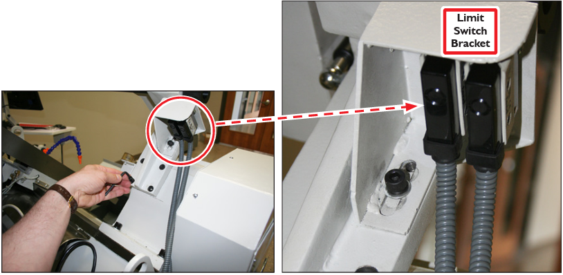
Locate and mount the Limit Switch bracket using screws pre-threaded in the main chuck guard bracket (see Figure 3).
NOTE: The Limit Switches and bracket are pre-wired to the lathe.
Install Back Splash
-
Position Back Splash at the back of lathe, ensuring the slot located at the bottom of Back Splash fits over the back edge of lathe pedestal (see Figure 4 and Figure 5).
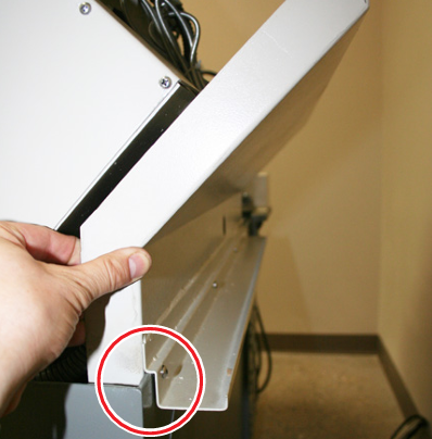
-
Attach the Back Splash to the lathe pedestal with four 5 mm Socket Head Cap Screws (see Figure 6).
Connect Back Splash
-
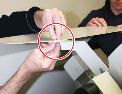
Connect the top of the Back Splash to the Chuck Guard using two 6 mm Socket head cap Screws, lock washers, flat washers and nuts (see Figure 7).
Install Front Splash
-
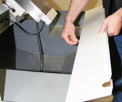
Attach the Front Splash guard to lathe’s front pedestal using three 6 mm long Socket Head Cap Screws (see Figure 8 and Figure 9).
-
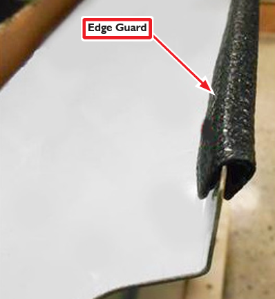
Slip Edge Guard over top edge of Front Splash as shown in Figure 10.
Install Splash Flap
-
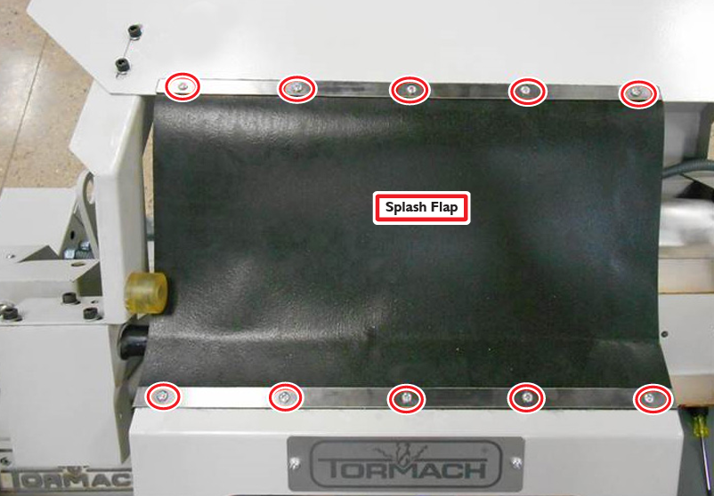
Install the Splash Flap to prevent spray back of coolant above the Chuck Guard with 10 Phillips Head Screws, lock washers, and nuts as shown in Figure 11.
NOTE: Some tweaking of the upper Back Splash bracket may be required to align the Splash Flap holes.
Adjust Chuck Guard
-
Tighten the two Limit Switch slotted nuts and verify they are secure (see Figure 12).
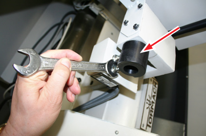
-
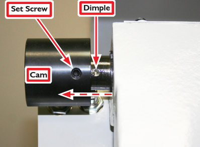
Verify the door cam position by loosening the set screw on the cam with a hex wrench; slide the cam slightly to the left to expose the dimpled pivot shaft (see Figure 13).
-
With set screw still loose, slide the cam back over the shaft ensuring screw and dimple are aligned. Then, slowly tighten screw until it drops into dimple; tighten firmly. See Figure 13 to review correct positioning when Chuck Guard is closed.
-
Verify the Limit Switch adjustment by lifting the Chuck Guard. If correctly adjusted, two clicks are heard as the rollers run down the cam. If two clicks are not heard, adjust the switch height accordingly.
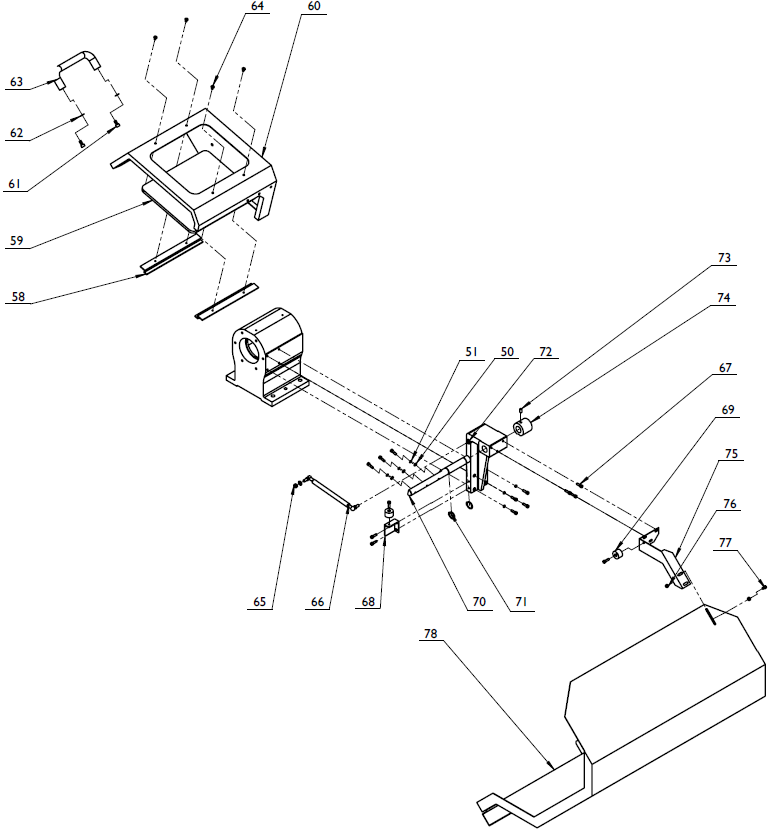
Parts List
|
ID |
PN |
Description |
|
50 |
34298 |
Washer, Flat M6 |
|
51 |
34299 |
Washer, Lock M6 |
|
58 |
34306 |
Window Bracket |
|
59 |
34307 |
Window |
|
60 |
34308 |
Chuck Guard |
|
61 |
34309 |
Screw, M8x16 |
|
62 |
34310 |
Washer, M8 |
|
63 |
34311 |
Handle |
|
64 |
34312 |
Screw, M5x10 |
|
65 |
34313 |
Nut, M8 |
|
66 |
34314 |
Air Spring |
|
67 |
34315 |
Screw, M6x20 |
|
68 |
34316 |
Bracket |
|
69 |
34317 |
Bumper |
|
70 |
34318 |
Pivot Shaft |
|
71 |
34319 |
Retaining Ring |
|
72 |
34320 |
Main Guard Mount Arm |
|
73 |
34321 |
Set Screw, M8x14 |
|
74 |
34322 |
Cam, Door Switch |
|
75 |
34323 |
Mounting Bracket |
|
76 |
34324 |
Nut, M6 |
|
77 |
34325 |
Screw, M6x12 |
|
78 |
34326 |
Back Splash Panel |
|
(not shown) |
35691 |
Switch Bracket |
To view a PDF version of your manual, go to Tormach document TD10243.
If you have additional questions, we can help. Create a support ticket with Tormach Technical Support at tormach.com/how-to-submit-a-support-ticket for guidance on how to proceed.