Background
The idea of providing power to your machine seems simple: just plug it in. In reality, there are a number of other components used in order to provide power appropriately safety for you and the machine, including (but not limited to):
-
The main disconnect switch
-
Fuses and/or circuit breakers
-
Emergency stop switch/button
-
Separate latching circuits for the spindle and rest of the machine
-
Transformers, which change the electricity to the appropriate value
Even with all of these components, you can systematically locate nearly any problem with just a multimeter.
Tools
-
Multimeter
Twist Out the Emergency Stop Button
Reason: The Emergency Stop button is pushed in.
-
Twist out the Emergency Stop button and press the Reset button.
The Reset button doesn't illuminate until after you:
-
Twist out the Emergency Stop button.
-
Press the Reset button.
Reset the Building’s Mains Breaker
Reason: The shop or building’s mains breaker is turned off.
-
Examine the building’s breaker. If it’s not already on, turn it on.
-
Using a digital multimeter, measure to inspect and verify that you have power at the outlet.
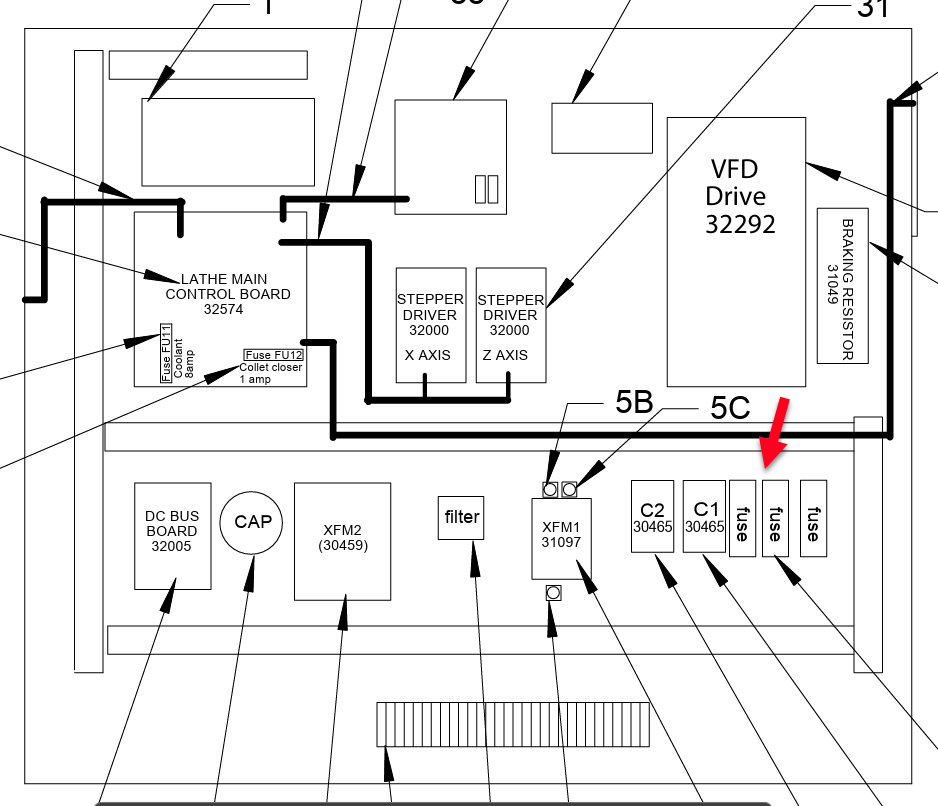
Inspect the Power Entering the Machine
Reason: The Main Disconnect switch is in the Off position.
-
Examine the Main Disconnect switch. If it’s not already in the On position, turn it on and try to take your machine out of reset.
-
Measure the voltage coming out of your Main Disconnect switch.
-
Identify the wires as indicated in the table.
-
If you measure the correct Vac, continue.
-
If you do not any Vac, you either have a loose wire or a faulty Main Disconnect switch.
-
|
Machine |
Wires |
Measure for… |
|---|---|---|
|
15L |
L1 and L2 |
230 Vac nominal |
Check the FU1 and FU2 Fuses
Reason: Fuse is blown.
-
Identify your machines main fuses.
-
Power down the machine, and remove both fuses.
-
Check both fuses using the following process: Checking a Fuse on a Tormach Machine.
-
If any fuse is blown, replace it.
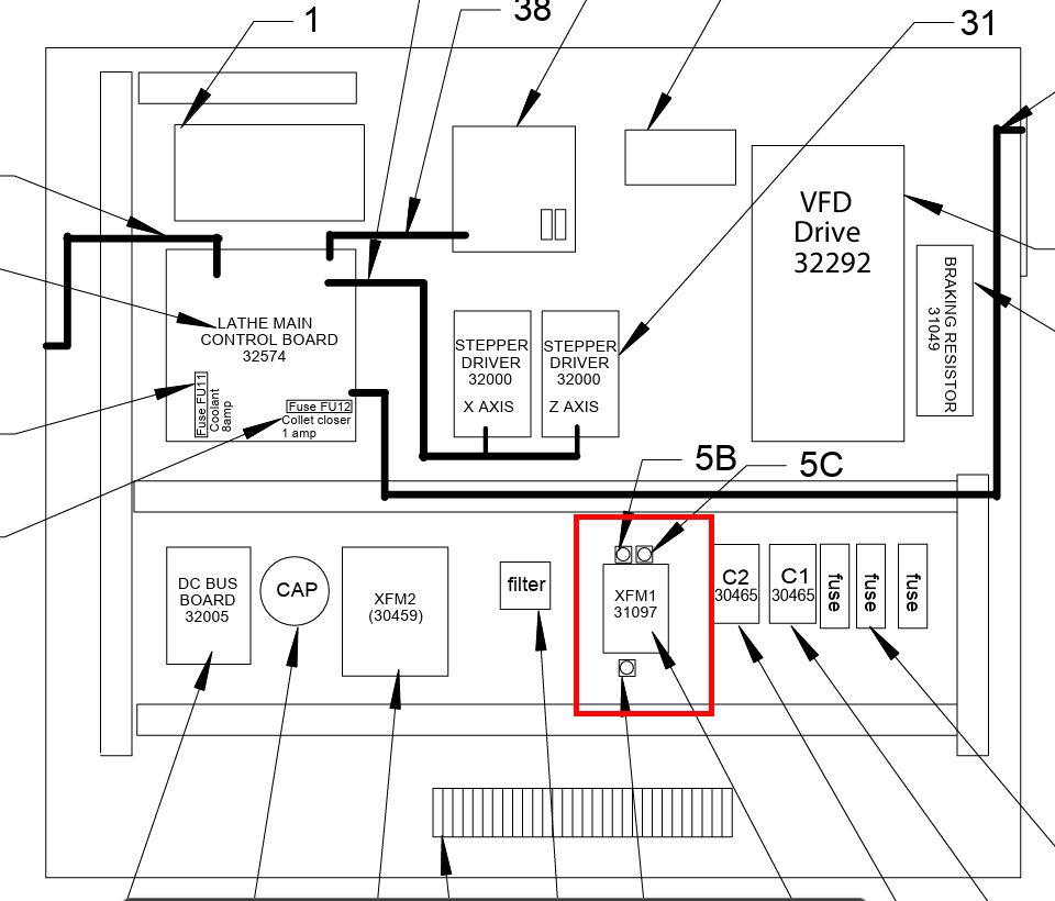
Inspect the XFM1 Transformer
Reason: Transformer fuse blown or transformer shorted.
-
Take a Vac reading between wires 100-102.
-
If no voltage is present, power down the machine, and check all three fuses on the transformer.
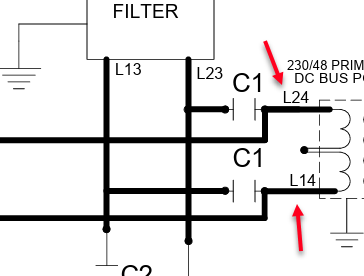
Check the C1 Contactor
Reason: The C1 is defective.
-
Power on the machine and take it out of reset.
-
Inspect the C1 to see if the center bar has been pulled in.
-
If bar is in: The C1 is latched. Using a digital multimeter set to Vac, measure for 220 Vac between:
-
L14
-
L24
-
-
-
Press and hold the Reset button on the operator box and observe the C1. Then release the Reset button and observe the C1.
-
If the bar only stays in when the button is pressed: There is a loose coil wire, short, or the C1 has malfunctioned.
-
If the bar never gets pulled in: Go back to the previous troubleshooting topics to ensure your machine is receiving power.
-
Inspect the Emergency Stop circuit
Reason: The circuit has been interrupted.
Our main indicator of the source of the fault is the machine LED light on the 15L’s electrical cabinet. It’s status indicates which subsystem to begin checking for the estop fault.
-
Dark - the estop circuit has been interrupted
-
Solid - communication with Pathpilot has dropped
-
Blinking 50/50 on/off - VFD has faulted
-
Blinking 10/90 on/off - turret tool change has failed
Estop circuit has been interrupted
-
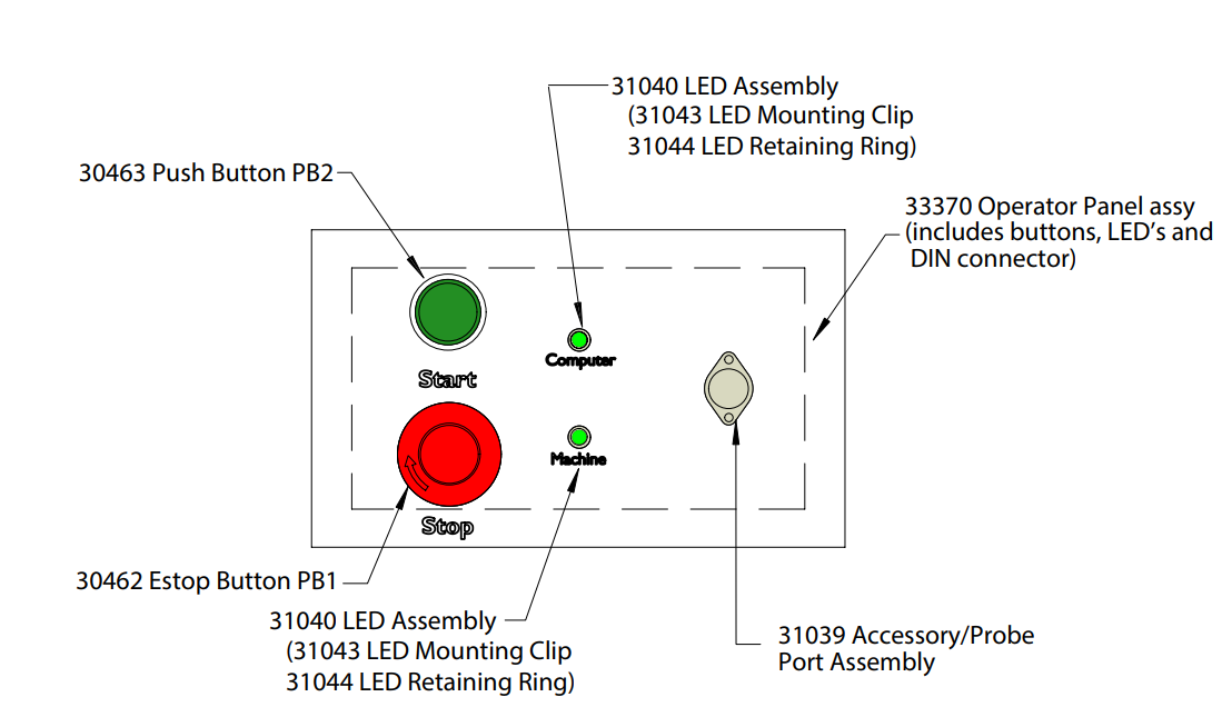
Verify that the estop buttons are not tripped. The 15L is equipped with two estop buttons:
-
On the front of the electrical cabinet
-
On the tray of the controller arm
-
-
Verify that fuses FU1, FU2, FU3, FU5, and FU7 are not blown and have a reading of between 0.1 and 1 ohm. Below or above 0.1 to 1 ohm indicate a fuse that needs to be replaced.
-
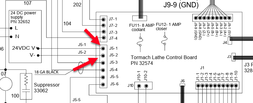
Verify that the 24v DC power supply is outputting at least 24v and less than 28v.
-
Verify that the main control board is receiving 24v DC power by measuring between terminals J5-1 and J5-2.
Communication with the controller has been interrupted
-
Verify that the DB25 cable is fully inserted to the machine and the controller.
-
Verify conductivity on the pins of each of the conductors in the DB25 cable and J4 cable.
-
If using a tower controller, check the Mesa card for solid red lights, indicating a hardware fault on the Mesa card.