Purpose
This document gives instructions on installing and using a 6 in. and 8 in. 4th Axis for M/MX.
Product Information
Product:
Set Up the 6 in. or 8 in. Rotary Table
Complete the following steps in the order listed:
Before You Begin
NOTICE! Before you begin to operate the 4th Axis, you must make sure that the rotary table is lubricated and adjusted for backlash. For information, see "Maintenance" (page 12).
Required Tools
This procedure requires the following tools. Collect them before you begin.
-
#2 Phillips screwdriver
-
Dead-blow hammer (or similar)
-
Magnetic dial indicator
-
Newspaper (or similar)
Unpack the 4th Axis
-
Inspect the item(s):
-
Photograph any damage that may have occurred during shipping.
-
Note any damage on the delivery receipt before signing for the shipment.
-
Verify the received goods against the packing list.
If there is any damage or shortages, you must contact Tormach within 30 days of receipt. Create a support ticket with Tormach Technical Support at tormach.com/how-to-submit-a-support-ticket for guidance on how to proceed.
-
-
Make sure that all loose parts are removed from the package before discarding any shipping materials.
Install the 4th Axis
Complete the following steps in the order listed:
Mount the Rotary Table
-
Prevent rust from forming on the machine table from trapped water-based coolants: put a thin film of oil (WD-40® or similar) on the surfaces.
-
Depending on your rotary table, do one of the following:
-
Standard Rotary Table (6 in. or 8 in.) Put the rotary table on the left side of the machine table.
-
Super Spacer or Tilting Rotary Table (6 in. or 8 in.) Put the rotary table on the right side of the machine table.
-
-
Loosely attach the rotary table toe clamps to the machine table.
NOTE: The components are left loose so that you can adjust the rotary table. -
Attach a magnetic dial indicator to the spindle head of the machine.
-
Put the dial indicator on the rotary table so that it will measure across the platter of the rotary table.
-
Jog the machine from side-to-side in the Y direction to indicate across the platter.
-
Use a dead blow hammer to tap the rotary table and adjust its position and reduce any misalignment determined in Step 6.
-
Completely tighten the rotary table toe clamps to secure the rotary table to the machine table.
Set the Driver DIP Switches
Depending on which rotary table you're using, set the DIP switches on the motor driver as detailed in the following tables.
|
6 in. Standard or Tilting |
|
|
Dip Switch |
Position |
|
1 |
On |
|
2 |
On |
|
3 |
Off |
|
4 |
Off |
|
5 |
Off |
|
6 |
On |
|
7 |
On |
|
8 |
Off |
|
6 in. Super Spacer, or 8 in. Standard, Tilting, or Super Spacer |
|
|
Dip Switch |
Position |
|
1 |
On |
|
2 |
Off |
|
3 |
Off |
|
4 |
Off |
|
5 |
Off |
|
6 |
On |
|
7 |
On |
|
8 |
Off |
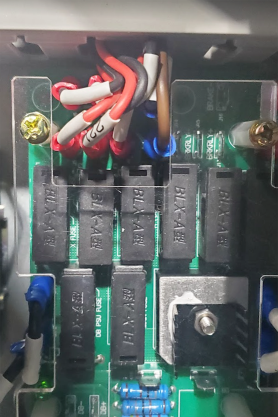
Install the A-Axis Motor Driver
WARNING! Electrical Shock Hazard: You must power off the machine before making any electrical connections. If you don't, there's a risk of electrocution or shock.
-
Power off the machine and the PathPilot controller.
-
Push in the machine's red Emergency Stop button, which removes power to motion control.
-
From the PathPilot interface, select Exit.
-
Turn the Main Disconnect switch to OFF on the side of the electrical cabinet.
-
-
Verify that you've correctly set the DIP switches on your stepper driver.
-
Remove the top, right, and middle (above the DC-BUS board) wire trough covers in the electrical cabinet.
-
Find the ribbon cable (labeled 423.4) in the top wire trough.
-
Find the green connector and wires in the right wire trough.
-
Install the motor driver in the electrical cabinet with a #2 Phillips screwdriver.
-
Connect the ribbon cable to the motor driver.
-
Apply dielectric grease to the power connector, and then connect it to the motor driver.
-
From the green connector, follow wire 240 (blue) and wire 241 (brown) to where they end in the wire trough and pull them out.
-
Connect the loose end of wire 241 (brown) to the A+ terminal on the DC bus board and connect wire 240 (blue) to the A- terminal of the DC bus board.
-
Put back the wire trough covers.
Verify the Installation
-
Make sure that all wires on the motor driver and the DC-BUS board are completely connected.
-
Replace the wire trough covers.
-
Connect the rotary table to the A-Axis Encoder connector on the side of the electrical cabinet.
-
Power on the machine and the PathPilot controller.
-
Turn the Main Disconnect switch to ON on the side of the electrical cabinet.
-
Twist out the machine's red Emergency Stop button, which enables movement to the machine axes and the spindle.
-
Press the Reset button.
-
Bring the machine out of reset and reference it.
-
-
From the PathPilot interface, test the movement of the rotary table:
-
Press COMMA on the keyboard to jog the rotary table in the -A direction.
-
Press PERIOD on the keyboard to jog the rotary table in the +A direction.
Operation
Read the following sections to understand how to operate the 4th Axis:
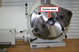
About the Center Hole
The center hole is ground to an MT taper, or a through bore, to fit workholding. On rotary tables with an MT taper, there is also a shallow, concentric pilot hole, used to locate a chuck or other tooling.
Make sure that coolant does not enter the moving rotary table components. If it does, go to "Examine the 4th Axis for Coolant Resistance".
Align the Angle of the Tilt Position
-
Use the Vernier scale to align the angle of the 6 in. Tilting Rotary Table or 8 in. Tilting Rotary Table when moving from horizontal to vertical.
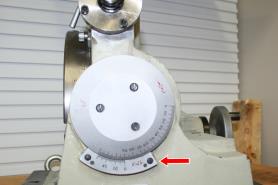
NOTE: It's easier to setup chucks or fixtures while the rotary table is in the horizontal position, and then move the rotary table to the vertical position.
Distribute Wear on the Rotary Table
We recommend distributing wear over the whole of the worm gear. Do the following:
-
When doing long runs of constant back-and-forth movement, occasionally reposition the table top and workholding fixture.
-
If the moves are close to 180°, continue rotating in the same direction to the start point, rather than returning in the opposite direction.
-
Program the start point to change a few degrees each time (if the part permits).
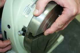
Lock the Tilt Position
You must lock the tilt position on the 6 in. Tilting Rotary Table or 8 in. Tilting Rotary Table before machining. To lock the tilt position:
-
Set the desired tilt of the rotary table.
-
Tighten the two tilt clamps.
The tilt position is locked in place.
Set a Reference Location
To read angles directly off the table:
-
Loosen the clamp holding the adjustable reference mark in place, and then move the pointer to an exact degree mark.
Tighten the Rotary Clamps
To keep the table from rotating during heavy milling operations:
-
Use the clamp handles to tighten the rotary clamps.
To allow the rotary table to rotate freely, make sure that the rotary clamps are loosened during motorized rotation.
To prevent the rotary table form losing the correct position, make sure that the rotary clamps are not too tight during a move.
Turn the Rotary Table by Hand
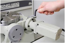
Power is transmitted from the A-axis motor driver to the rotary table by a worm gear at the end of the drive shaft. The eccentric lock stops the eccentric sleeve from rotating.
To turn the rotary table by hand, you must disengage the worm gear. To disengage the worm gear:
-
Loosen the eccentric lock.
-
Rotate the eccentric: Turn the motor mount as far as it will rotate in the clockwise direction (counterclockwise on super spacer rotary tables).
-
Tighten the eccentric lock.
The worm gear is disengaged.
To reengage the worm gear:
NOTICE! You must use the eccentric lock before engaging the worm drive. If you do not, there is a risk that the motor driver could disengaging during use.
-
Loosen the eccentric lock.
-
Rotate the eccentric: Turn the motor mount as far as it will rotate in the counterclockwise direction (clockwise on super spacer rotary tables).
-
Tighten the eccentric lock.
The worm gear is engaged. -
Make sure that the worm is completely engaged: If necessary, rotate the rotary table slightly (by hand) to engage the worm gear in the ring gear.
NOTICE! The worm must be completely engaged. If it's not, the rotary table will exhibit excessive backlash.
Workholding Reference
Direct Mount to Rotary Table
Use the T-slots in combination with T-nuts and a clamp set to hold work directly to the rotary table.
NOTE: 6 in. rotary tables have 10 mm T-slots. 8 in. rotary tables have 12 mm T-slots.
Alternatively, use bolts and T-nuts to attach a vice or custom fixture plate to the rotary table.
2-Jaw, 3-Jaw, or 4-Jaw Chuck
2-Jaw Chuck
The 2-Jaw Chuck for a 6-in. Table (PN 32627) provides rapid prototype workholding. The set includes a self-centering 2-jaw chuck with an adapter plate and mounting hardware, including jaw plates. The 2-Jaw Chuck for an 8-in. Table (PN 32622) includes a MT3 adapter ring.
3-Jaw Chuck
Use a 3-Jaw Chuck for 6 in. Table (PN 30292) or 3-Jaw Chuck for 8 in. Table (PN 30291).
4-Jaw Chuck
Use a 4-Jaw Chuck for 6 in. Table (PN 31721) or 4-Jaw Chuck for 8 in. Table (PN 30293). Each chuck includes an adapter plate and pin for mounting the chuck to the table and centering it to the rotational axis. Each chuck comes with both inside and outside interchangeable jaw sets.
5C Collet Adapter/Fixture
A 5C Collet Adapter for 8 in. Table (PN 30294) includes an adapter plate for mounting and centering the holder.
Use the T-slots to mount a 5C Collet Fixture for 6 in. Rotary Table (PN 31414) or 5C Collet Fixture for 8 in. Rotary Table (PN 31415).
MT2 or MT3 Alignment Kits
On 6 in. rotary tables, use an MT2 Alignment Kit for ER32 Collet Fixture (PN 34382).
On 8 in. rotary tables, use an MT3 Alignment Kit for ER32 Collet Fixture (PN 34383).
MT3 Collet and Drawbolt
On 8 in. rotary tables, use an MT3 collet, held in with a drawbolt. Use it in combination with a Tormach Tooling System (TTS) tool holder as a low-cost method for holding slender bar stock.
On 6 in. rotary tables, use an MT2 collet.
Maintenance
Read the following sections to understand how to maintain the 4th Axis:
Adjust the Backlash
NOTICE! You must complete the steps in this procedure to adjust the backlash. If you do not adjust the backlash, it could result in premature wear on the rotary table.
To Set the Backlash by Positioning the Backlash Adjustment Screw
-
Identify the backlash adjustment screw: Remove the protective cover screw on top of it, or loosen a jam nut.
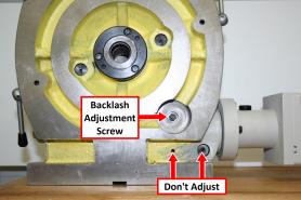
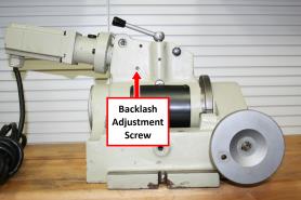
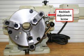
-
Loosen the backlash adjustment screw six turns counterclockwise.
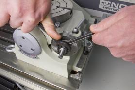
-
Disengage the eccentric lock and clamp handles.
-
Engage the worm gear: Rotate it completely (counterclockwise on standard and tilting rotary tables; clockwise on super spacer rotary tables).
-
Verify that the rotary table does not turn. It doesn't turn when the motor is engaged.
-
Use one hand to put counterclockwise pressure on the motor (clockwise on super spacer rotary tables), and slowly tighten the set screw until you feel resistance to the pressure you're applying.
Tip! Move slowly — the resistance could be subtle.
The set screw is just against the worm drive. -
Tighten the set screw a quarter-turn. The motor rotates slightly, and creates a gap (for an oil film) between table and worm gear.
-
Replace the protective cover screw.
To Set the Backlash by the Numbers
-
Adjust for a minimum backlash of 30 arc-seconds. Measured at the outer circumference of an 8-in. diameter circle with a dial indicator, 30 arc-seconds will be 0.0006 in. of lost motion.
Setting the backlash to 60 arc-seconds will sustain a thicker oil film, yielding lower friction and longer life. Measured at the outer circumference of an 8-in. diameter circle with a dial indicator, 60 arc-seconds is 0.0012 in. of lost motion.
We do not recommend setting the backlash greater than 90 arc-seconds (1.5 arc-minutes). It won't improve the life of the mechanism, and could result in chatter during machine operations.
About Backlash
Backlash is an important element in managing overall accuracy. On a rotary table, a number of internal sliding surfaces depend on a hydrodynamic oil film for low friction and long service life. The adjustment of clearances between these surfaces helps to achieve precision and extends service life — much like the adjustment of the lead screw nut and gibs on a mill or a lathe.
If the backlash is adjusted to zero, the worm screw (and other parts) are subjected to excessive wear and friction — which may lead to stalling of the rotary table. As the worm screw turns, the oil shears off at the gear interface, and provides no film to protect against metal-to-metal wear.
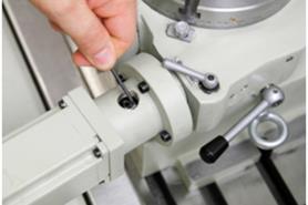
Adjust the Lock Nut
You must adjust the lock nut to adjust for wear in the worm gear.
-
Loosen the socket head cap screw and the set screw on the motor coupling. Do not remove the screws.
-
Remove the four mounting screws securing the motor to the motor mount.
-
Remove the motor — with the coupling still attached — from the motor mount.
-
Put grease on the back side of the spacer.
-
Use two spanner wrenches to tighten (or loosen) the lock nuts.
-
Adjust the spacer nut so that — when turned by hand — there is no axial play in the worm shaft, and so that the shaft moves freely. Do not over-tighten the lock nut.
Adjust the Rotary Table
To test for correct axial adjustment:
-
Disengage the worm.
-
Rotate the table by hand. You should feel a slight drag. If you do not feel a drag, do the following:
-
Use a flat-head screwdriver to loosen the three screws in the retaining plate two turns.
-
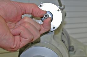
Use an Adjustable Pin Spanner Wrench (PN 31118) to tighten or loosen the retaining plate.
-
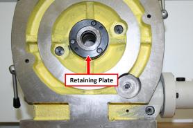
c. Rotate the plate clockwise to increase drag, or counterclockwise to decrease drag.
Examine the 4th Axis for Coolant Resistance
To make sure that the 4th Axis is resistant to coolant, regularly do the following:
-
Use thread seal tape to seal the set screw on the motor mount.
-
Position the motor so that its cord points down when the motor is engaged. Depending on the operational position (horizontal or vertical), you may have to reposition the motor with respect to the motor mount.
-
Make sure that the paint is maintained on the motor body — in particular, the magnetic laminations in the center.
-
Examine the oil view port for a milky fluid or raw coolant.
To remove coolant from the rotary table:
-
Drain the coolant from the rotary table.
-
Refill with one of the following:
-
AGMA 2 gear oil
-
SAE 30 weight motor oil
About the Rotary Table and Coolant
The rotary table is designed to operate in the presence of coolant, but not when it's submersed in coolant. It's rarely a problem is coolant is dripping over the edge. However, it is a problem if there's a serious external coolant flow that submerses the joint between the rotating table and the base casting.
The electric motor is sealed against cutting fluids. Do not allow the following components to be subject to constant coolant flow or high-pressure coolant jets:
-
Motor
-
Motor cable
-
The joint between the rotating table and the base casting
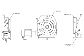
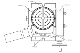
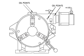
About the Rotary Table Lubrication System
There is an oil distribution system internal to the rotary table. As the table turns, it carries oil over the worm gear.
NOTE: The distribution system does not cover the sliding joint between the rotating table and the base casting, which is similar to the slideways of a mill and has a large, flat surface supported by an oil film.
The oil port on the edge of the rotary table (and on the base casting itself) provides oil to the sliding surfaces. It's important to occasionally oil the ports to maintain an oil film, which is essential to keep water and coolant away from the sliding joint. If you're using coolant, and you do not oil the ports, coolant will enter the rotary table.
NOTE: Coolant contains anti-corrosion agents which protect the table surfaces. A small amount of coolant and oil generally forms an emulsion, which you can see as a milky fluid inside the oil view port.
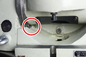
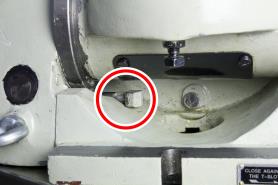
Examine the Locking Lugs
The 8 in. Tilting Rotary Table and 6 in. Tilting Rotary Table each have two locking lugs. When they are moved out of position (either intentionally or unintentionally), the rotary table will not tilt within the full range of motion. The more interior locking lug is difficult to realign with the recessed groove.
To manually align the interior locking lug:
-
Manually crank the handle and move the table to a position that allows access to the displaced part.
-
Use your fingers (or a small tool) to move the locking lug back into place. In its correct position, you should only see the cap of the locking lug.
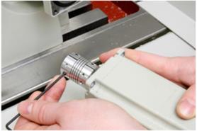
Examine the Motor Coupling
If a motor coupling is loose or cracked, the table will slip relative to motor rotation and, subsequently, lose position.
-
Remove the set screw on the motor mount.
-
Jog the motor until you can access the first of two coupling screws inside the motor mount.
-
Tighten the screws on the coupling.
To remove the motor coupling:
-
Loosen the socket head cap screw and the set screw on the motor coupling. Do not remove the screws.
-
Remove the four mounting screws securing the motor to the motor mount.
-
Remove the motor — with the coupling still attached — from the motor mount.
-
Inspect the coupling for defects. Do one of the following:
-
If the coupling is broken: remove the coupling, and replace with either the Coupling: 6-in. Rotary Table (PN 31840) or the Coupling: 8 in. Rotary Table (PN 30715).
-
If the coupling is not broken: Tighten the remaining coupling screws on the motor shaft.
-
Lubricate the Rotary Table
NOTICE! Never operate the 4th Axis without lubrication. Operating the 4th Axis without lubrication may void your warranty.
The rotary table is shipped without oil. Before operating, you must fill the rotary table with oil. Only use AGMA 2 gear oil or SAE 30 weight motor oil. Do not use way oil.
NOTE: After the rotary table is filled with oil, you must allow it to drain the excess oil, which may take up to two days. You may use the 4th Axis while it drains.
-
Identify the oil fittings on the rotary table.
-
On the standard rotary tables (6 in. Rotary Table or 8 in. Rotary Table), identify the oil reservoir.
-
Use a trigger-style oil can to fill the oil fittings: Insert the tip of the oil can into each fitting, and pump in oil until you can feel back pressure.
-
On the standard rotary tables (6 in. Rotary Table or 8 in. Rotary Table), fill the oil reservoir until the oil begins to leak out at the bottom of the table. If the If the oil reservoir is over-filled, it slowly leaks out until it reaches the correct level.
-
Put the rotary table on a stack of newspaper (or similar) to allow it to drain the excess oil.
Exploded Views and Parts Lists
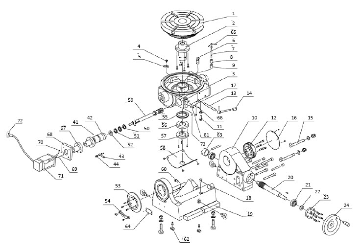
Standard Rotary Table Exploded View
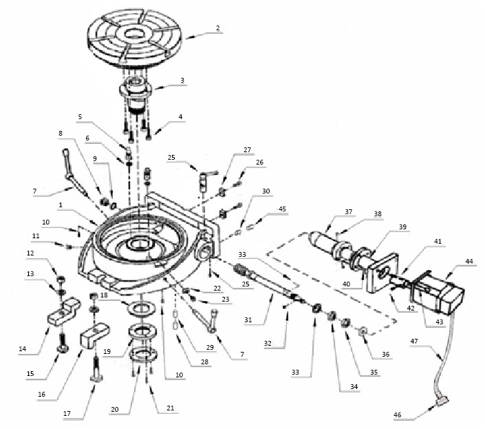
Standard Rotary Table Parts List
|
ID |
Description |
Quantity |
||
|
1 |
Base |
1 |
||
|
2 |
Table |
1 |
||
|
3 |
Taper sleeve |
1 |
||
|
4 |
Socket head bolt* |
4 |
||
|
5 |
Table clamp |
2 |
||
|
6 |
O-ring dash 110* |
2 |
||
|
7 |
Handle assembly |
2 |
||
|
8 |
Sight glass |
1 |
||
|
9 |
O-ring |
1 |
||
|
10 |
Dog point set screw |
2 |
||
|
11 |
Plug |
1 |
||
|
12 |
Hex nut* |
4 |
||
|
13 |
Washer |
2 |
||
|
14 |
Clamp |
1 |
||
|
15 |
T-bolt |
1 |
||
|
16 |
L-clamp |
2 |
||
|
17 |
T-bolt |
1 |
||
|
18 |
Ring |
1 |
||
|
19 |
Table nut |
1 |
||
|
20 |
Retaining plate |
1 |
||
|
21 |
Fillister head screw |
3 |
||
|
22 |
Indicator |
1 |
||
|
23 |
Knob |
1 |
||
|
24 |
Set screw dog point |
1 |
||
|
25 |
Eccentric lock |
1 |
||
|
26 |
Socket head bolt* |
2 |
||
|
27 |
Locating key |
2 |
||
|
28 |
Set Screw* |
1 |
||
|
29 |
Backlash Adjustment Screw (PN 34380) |
1 |
||
|
30 |
Block |
1 |
||
|
31 |
Worm gear |
1 |
||
|
32 |
Key |
1 |
||
|
33 |
Dowel pin |
1 |
||
|
34 |
Spacer |
1 |
||
|
35 |
Lock nut |
2 |
||
|
36 |
Spacer with keyway |
1 |
||
|
37 |
Eccentric sleeve |
1 |
||
|
38 |
Fillister head screw |
2 |
||
|
39 |
Motor mount |
1 |
||
|
40 |
Socket head screw* |
4 |
||
|
41 |
Coupling 6” (PN 31840) 8” (PN 30715) |
1 |
||
|
42 |
Set Screw* |
1 |
||
|
43 |
Socket head screw* |
4 |
||
|
44 |
Motor complete 6” (PN 32677) 8” (PN 32379) |
1 |
||
|
45 |
Oil plug |
1 |
||
|
46 |
Power plug |
1 |
||
|
47 |
Cable |
1 |
||
|
(not shown) |
Oil fitting (PN 35220) |
|
||
|
*Standard hardware items |
|
|
||
Tilting Rotary Table Exploded View
Tilting Rotary Table Parts List
|
ID |
Description |
Quantity |
|
1 |
Table |
1 |
|
2 |
Taper sleeve |
1 |
|
3 |
Base |
1 |
|
4 |
Knob |
1 |
|
5 |
Indicator |
1 |
|
6 |
Table clamp |
1 |
|
7 |
Bolt |
1 |
|
8 |
Locking pad |
1 |
|
9 |
Locking pillar |
1 |
|
10 |
Supporter |
1 |
|
11 |
Positioning screw |
1 |
|
12 |
Helical gear |
1 |
|
13 |
Eccentric axle |
1 |
|
14 |
Table clamp handle |
1 |
|
15 |
Locking lug |
2 |
|
16 |
Cover |
1 |
|
17 |
Backlash adjustment screw (PN 34380) |
1 |
|
18 |
Positioning block |
1 |
|
19 |
Base |
1 |
|
20 |
Screw bar |
1 |
|
21 |
Bearing |
1 |
|
22 |
Sealing |
1 |
|
23 |
Cover |
1 |
|
24 |
Handle wheel |
1 |
|
41 |
Pin |
1 |
|
42 |
Eccentric sleeve |
1 |
|
43 |
Handle |
1 |
|
44 |
Bolt |
1 |
|
50 |
Spacer |
1 |
|
51 |
Spanner nut |
2 |
|
52 |
Spacer |
1 |
|
53 |
Indicate plate |
1 |
|
54 |
Vernier |
1 |
|
55 |
Spacer |
1 |
|
56 |
Locating nut |
1 |
|
57 |
Locating nut |
— |
|
58 |
Cover |
— |
|
59 |
Worm gear |
— |
|
60 |
Positioning block |
1 |
|
61 |
Pin |
1 |
|
62 |
Locating key |
2 |
|
63 |
Block |
1 |
|
64 |
Name plate |
1 |
|
65 |
Eccentric lock |
1 |
|
66 |
Bolt |
1 |
|
68 |
Socket head screw |
1 |
|
69 |
Motor coupling 6” (PN 31840) 8” (PN 30715) |
1 |
|
70 |
Set screw |
2 |
|
71 |
Motor complete 6” (PN 32677) 8” (PN 32379) |
1 |
|
72 |
Power plug |
1 |
|
(not shown) |
Oil Fitting (PN 35220) |
— |
Super Spacer Rotary Table Exploded View
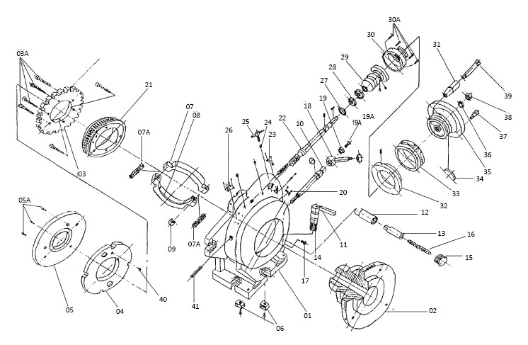
Super Spacer Rotary Table Parts List
|
ID |
Description |
|
1 |
Body |
|
2 |
Spindle |
|
3 |
Index plate |
|
3A |
Screw |
|
4 |
Masking plate |
|
5 |
Bumper plate |
|
5A |
Screw |
|
6 |
Centering key w/ screw |
|
7 |
Brake shoe |
|
7A |
Spring |
|
8 |
Brake shoe |
|
9 |
Screw |
|
10 |
Screw arbor |
|
11 |
Index handle |
|
12 |
Sleeve |
|
13 |
Index pin |
|
14 |
Gear shaft |
|
15 |
Cover |
|
16 |
Spring |
|
17 |
Screw |
|
18 |
Clamp handle |
|
19 |
Bushing |
|
19A |
Screw |
|
20 |
Vernier scale |
|
21 |
Ring gear |
|
22 |
Worm gear |
|
23 |
Indicating plate |
|
24 |
Pin w/ inclined surface |
|
25 |
Handle |
|
26 |
Name plate |
|
27 |
Spacer |
|
28 |
Screw nut |
|
29 |
Eccentric sleeve |
|
30 |
Shaft sleeve |
|
31 |
Set screw |
|
32 |
Backlash adjustment screw (PN 34380) |
|
40 |
Locating pin for masking plate |
|
41 |
Screw |
|
(not shown) |
Oil fitting (PN 35220) |
To view a PDF version of your manual, go to Tormach document TD10552.
If you have additional questions, we can help. Create a support ticket with Tormach Technical Support at tormach.com/how-to-submit-a-support-ticket for guidance on how to proceed.