Purpose
This document gives instructions on installing the FogBuster Coolant Kit on a mill.
Product Information
Product:
|
Quantity |
Description |
|
12 in. |
Blue Tubing |
|
1 |
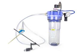
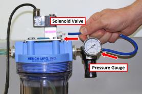
Fluid Reservoir with Pressure Gauge |
|
1 |
Fog Buster Sprayer Head |
|
1 |
Mounting Bracket |
|
4 |
Mounting Bracket Bolts |
|
2 |
Phillips Head Screws |
|
1 |
Quick-Mount System |
|
1 |
Solenoid Valve (PN 32644) |
|
1 |
Solenoid Valve Fitting |
NOTE: If any items are missing, we can help. Create a support ticket with Tormach Technical Support at tormach.com/how-to-submit-a-support-ticket for guidance on how to proceed.
Installation
Complete the following steps in the order listed:
Assemble the FogBuster
-
Wind thread seal tape around the valve fitting.
-
Put the valve fitting in to the solenoid as shown in the following image. Verify that the valve fitting is installed in the correct airflow direction.
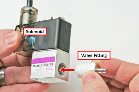
NOTE: For more information on air connections, see "Make Air Connections".
-
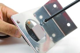
Attach the solenoid valve below the mounting bracket with two Phillips head screws.
-
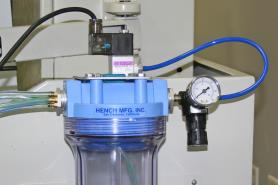
Attach the fluid reservoir to the mounting bracket with four mounting bracket bolts.
Tip! To help with threading, you can add a few drops of lubricating oil in each bolt hole.
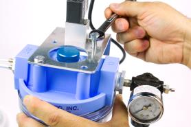
-
(Optional) Loosen the nut on top of the solenoid, and rotate the solenoid until it's in the desired position.
-
Put the 12-in. blue tubing on the pressure gauge and the solenoid valve.
NOTE: Once the blue tubing is connected, you must cut it to remove it. If you need a replacement, use tubing with a 1/4 in. (6.35 mm) outer diameter.
Attach the FogBuster to the Machine
-
Attach the fluid reservoir in a convenient location on the machine. For best results, we suggest that you attach it in a location so that it's approximately at the same height as the sprayer head.
-
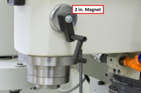
Attach the 2 in. magnet on the quick-mount system to the spindle head.
-
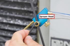
Attach the sprayer head to the quick-mount system with a hex head wrench as shown in the following image.
Setup
Complete the following steps in the order listed:
Fill with Coolant
-
Remove the reservoir tank from the its lid.
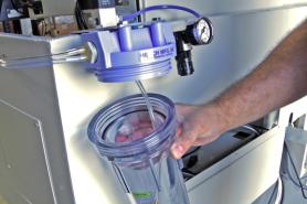
-
Fill the reservoir tank with coolant until the coolant level is just below the rubber seal. Verify that the reservoir tank isn't overfilled.
-
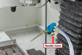
Move the nozzle tip on the sprayer head toward the cutting tool.
-
Open the needle valve to adjust the coolant flow to cutting tool. Verify that the needle valve isn't overtightened.
Make Power Connections
Route the loose end of the power cord to the electrical cabinet, and connect it to the Coolant Pump Power outlet.
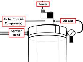
Make Air Connections
-
Route the air line from the air compressor to the solenoid valve.
-
Put the air line in the solenoid valve as shown in the following image.
To view a PDF version of your manual, go to Tormach document TD10144.
If you have additional questions, we can help. Create a support ticket with Tormach Technical Support at tormach.com/how-to-submit-a-support-ticket for guidance on how to proceed.