Purpose
This document gives instructions on installing, using, and troubleshooting the SmartCool on a mill.
Product Information
Product: SmartCool (PN 37167)
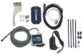
|
Quantity |
Description |
|
4 |
7-in. Cable Tie (PN 32791) |
|
1 |
AC/DC Power Adapter |
|
4 |
Cable Tie Anchor, Screw Mount, M5 (PN 31460) |
|
1 |
Control Module |
|
1 |
Screw, Socket Head Cap, M5 × 0.8 - 12 mm (PN 31353) |
|
2 |
Washer, Flat (Large), M6 |
|
2 |
Washer, Flat (Small), M6 |
|
2 |
Screw, Button Head Cap, M6 × 10 mm |
|
2 |
Screw, Socket Head Cap, M6 × 16 mm |
|
1 |
Mounting Bracket |
|
1 |
Screw, Sheet Metal (PN 31718) |
|
1 |
SmartCool Head Unit |
|
1 |
Tube |
|
1 |
USB Cable |
NOTE: If any items are missing, we can help. Create a support ticket with Tormach Technical Support at tormach.com/how-to-submit-a-support-ticket for guidance on how to proceed.
Required Tools
This procedure requires the following tools. Collect them before you begin.
-
Adjustable wrench
-
Metric hex wrench set
-
Phillips screwdriver
-
Wire cutter
-
M6 × 1 tap (for PCNC 440 mills serial number 80075 and below)
Before You Begin
-
Mounting Bracket If you don’t have an (optional) Automatic Tool Changer (ATC), you must use an additional mounting bracket to install the SmartCool:
-
PathPilot v1.9.7 or Later Required PathPilot v1.9.7 or later is required to use these instructions. If you haven’t yet done so, download and install the latest version of PathPilot from tormach.com/pp-updates.
Installation
Complete the following steps in the order listed:
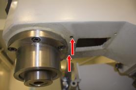
Install the Head Unit
-
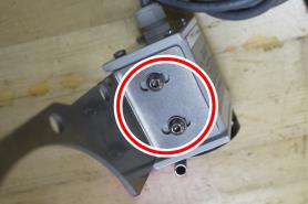
Identify the two pre-existing mounting holes behind the spindle on the head casting.
-
If necessary, clean the mounting holes of any paint.
-
If you have a PCNC 440 mill with serial number 80075 and below, you must first drill and tap two mounting holes:
-
Temporarily put the mounting bracket behind the spindle on the head casting.
-
Put a mark on the hole locations.
-
-
Drill and tap marks for use with a M6 × 1 mm screw.
-
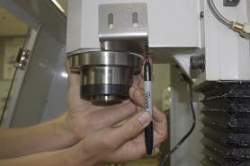
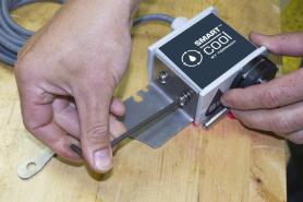
Loosely attach the SmartCool head unit to the mounting bracket with two M6 × 1 mm button head cap screws and two M6 small flat washers.
-
Put the SmartCool head unit roughly in the center of the mounting bracket’s slots.
-
You’ll make the final adjustments after the installation is complete to verify that the coolant stream is correctly positioned.
-
Loosely attach the mounting bracket to the two mounting holes with two M6 × 1 mm socket head cap screws and two M6 large flat washers.
-
Route the control cable from the SmartCool head unit through the mounting bracket, and then below the head casting.
Route the Cables
Cable routing varies based on your machine.
PCNC 770/PCNC 1100
-
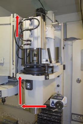
Open the spindle motor cabinet door.
-
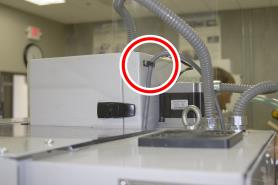
Route the control cable from the SmartCool head unit up the spindle column and through the inside of the spindle motor cabinet.
-
Secure the control cable from the SmartCool head unit to the machine with two cable ties and two cable tie mounts: one inside the spindle motor cabinet, and one on the head casting.
-
Route the control cable from the SmartCool head unit to the back of the machine based your specific mill configuration:
-
Power Drawbar Installed Route through power drawbar’s cable carrier and out to the back of the machine.
-
-
No Power Drawbar Installed Hold the control cable from the SmartCool head unit near the Z-axis motor mount plate. Then, slowly jog the spindle head up and down to verify clearance through the full range of motion in the Z direction. Loosen the center screw on Z-axis motor mount plate, and attach the control cable with one zip tie and one zip tie mount.
-
Slowly jog the spindle head up and down to verify that the control cable is free of obstruction from the machine movement.
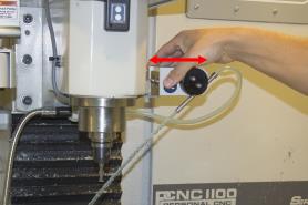
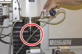
PCNC 440
-
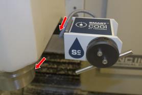
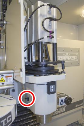
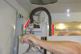
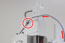
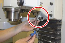
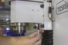
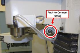
Route the control cable from the SmartCool head unit up the spindle column. Then, secure it with two cable mounts and two cable ties as shown in the following images.
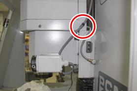
-
Slowly jog the spindle head up and down to verify that the control cable is free of obstruction from the machine movement.
Move the Flood Coolant Bracket
-
If you have an (optional) ATC installed, the coolant hose mount bracket is already relocated. Go to Step 5 of this section.
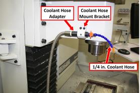
(Optional) If you have a flood coolant kit installed, remove the 1/4 in. coolant hose and coolant hose mount bracket. Then, set both aside.
-
Depending on your machine, identify the location for the mounting bracket:
-
All PCNC 770/PCNC 1100 Mills On the spindle casting, behind the spindle.
-
PCNC 440 Mills Serial Number 80075 and Below You must drill and tap one hole behind the SmartCool’s mounting bracket:
-
Temporarily put the relocation bracket on the spindle column flush with right edge of spindle head casting.
-
-
-
Mark the location of the hole.
-
Drill and tap the mark for a 6 mm screw.
-
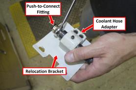
Attach the coolant hose mount bracket and the coolant hose adapter to the relocation bracket with two screws from the coolant hose mount bracket.
-
Attach the relocation bracket to the head casting in location that you identified in Step 2.
-
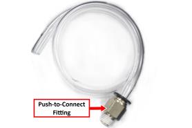
Remove the push-to-connect fitting from the tube. Then, install it on the coolant hose adapter with an adjustable wrench.
Make Coolant Connections
SmartCool units are pre-configured for use with flood coolant, but you can configure them to use mist coolant as the primary coolant source.
Flood Coolant
-
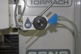
Connect the tube to the push-to-connect fitting on the relocation bracket.
-
Route the tube to the SmartCool head unit.
Mist Coolant
-
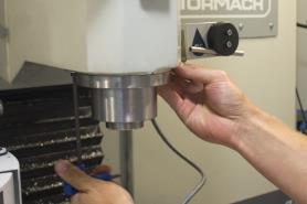
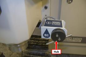
Identify the hub on the SmartCool head unit.
-
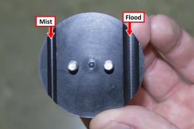
Remove the cap from the hub. Then, identify its two slots: one for flood, and one for mist coolant. Set the cap aside.
-
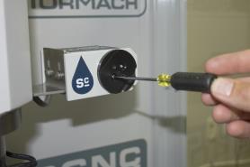
Remove the hub’s mounting plate from the front of the SmartCool head unit.
-
Identify the two slots (for flood and mist coolant). The mounting plate follows the same pattern as the cap.
-
Re-install the mounting plate with the mist slot on the bottom, and tighten the screws finger-tight.
-
Re-install the cap with the mist slot on the bottom. Insert the two hoses into the slots as shown in the following image, and tighten the screws finger-tight.
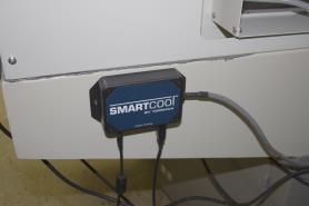
Make Control Module Connections
-
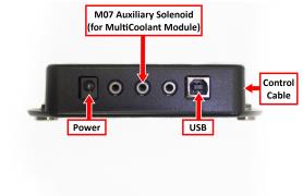
Connect the control module as follows:
-
Connect the AC/DC power adapter to the power port.
-
Connect the USB cable to the USB port.
-
Connect the control cable from the SmartCool head unit.
-
The control module is magnetic. Attach it to the back of the machine.
-
Route the USB cable to the PathPilot controller. Then, connect it to any available USB port.
-
Route the AC/DC power adapter to a power outlet.
NOTE: SmartCool can be plugged in and used at any time. The machine doesn’t need to power cycle for PathPilot to recognize SmartCool.
Calibrate the Height of the Coolant Flow
-
Using a tool of a known length, calibrate the height of the coolant flow from SmartCool by issuing a M08 or M07 command in PathPilot and mechanically adjusting the assembly installation on the spindle head casting.
-
Put a measured tool into the spindle and activate its length offset.
-
From the PathPilot interface, in the MDI Line DRO field, type M8 P0 to turn on flood coolant. Then, aim the stream at the tip of tool.
For information, see "Programming".
-
-
Watch the coolant stream: if necessary, adjust the SmartCool head unit within the mounting bracket to visually correct for uneven mounting. Adjust until the coolant stream is in line with the tip of the tool.
-
Tighten down the screws securing the SmartCool head unit to the mounting bracket.
-
If necessary, you can adjust the coolant stream further in PathPilot to position it on tool tip:
-
-
From the PathPilot interface, in the MDI Line DRO field, type ADMIN SMARTCOOL_OFFSET to raise or lower the coolant stream.
-
Use a positive value to move the coolant stream up; use a negative value to move the coolant stream down.
For information, see "Programming".
-
Programming
SmartCool has three programming modes:
-
Z0 Mode (default) Aims coolant stream at a Z0 plane or programmed distance from the Z0 plane.
-
Tool Tip Mode (M08 P~) Aims coolant stream at the tool tip or a programmed distance from the tool tip.
-
Wiggle Mode (M08 R~) Oscillates coolant stream between two programmed positions.
Program SmartCool using optional words to modify the standard coolant M-codes:
-
M07 Mist coolant or air on (secondary)
-
M08 Flood coolant on (primary)
-
M09 Coolant off
Optional words:
-
E~ Adjusts the Z position when using Z0 mode to aim target point of coolant stream.
-
P~ Defines the target point of coolant stream. The P word is optional; if the P word is omitted, the target point of the coolant stream is the Z0.
-
R~ Enables oscillating coolant stream (wiggle mode).
-
Q~ Enables pulsing of M07 or M08 solenoid in seconds. Requires SmartCool Multi-Cool Module (PN 37168).
Examples
To turn on flood coolant, program M08 P~ R~ E~
To turn on mist coolant or air, program M07 P~ R~ E~
To turn all coolant off, program M09
If the top of the workpiece is not at Z0, use an E word argument to maintain the coolant stream at the desired Z location.
When using an E or P word argument, units are defined by the active unit length as specified by G20 (inches) or G21 (millimeters).
To specify the time period between air blasts using the SmartCool Multi-Cool Module, use a Q word argument. Q is always in whole seconds. The Q word affects aiming; during the blast period, only M07 aiming is in effect.
The SmartCool head unit aims coolant using the top slot on the hub when only M07 is in effect; when M08 is in effect, aiming priority is switched to the bottom slot on the hub. M07 and M08 may be used simultaneously.
Examples
To turn on flood coolant and maintain the stream at Z0, program M08
To turn on flood coolant and maintain the stream at 1 unit above Z0, program M08 E1
To turn on flood coolant and aim the stream at the tool tip, program M08 P0
To turn on flood coolant and aim the stream at 1 unit above the tool tip, program M08 P1
To turn on flood coolant and aim the stream at 3 units below the tool tip, program M08 P-3
To turn on flood coolant, aim the stream at the tool tip, and oscillate between the tool tip and 3 units above the tool tip, program M08 P0 R3
To turn on flood coolant, maintain the stream at Z0, and oscillate between Z0 and 3 units above Z0, program M08 R3
To turn on mist coolant or air and aim the stream at Z0, program M07
To turn off all coolant, program M09
Keyboard Shortcuts
|
Keyboard Shortcut |
Use to... |
|
Alt+U |
Manually override PathPilot coolant control to point nozzle up* |
|
Alt+D |
Manually override PathPilot coolant control to point nozzle down* |
|
Alt+C |
Cancel manual override of PathPilot coolant control; reverts to automatic control |
|
Alt+M |
Toggle auxiliary solenoid on and off (requires SmartCool Multi-Cool Module (PN 37168)) |
|
*Cancel manual override with Alt+C or any subsequent M-code command. |
|
ADMIN Commands
The aiming of the SmartCool head unit can be fine-tuned to compensate for installation variance or a sagging coolant stream (non-linear).
|
Admin Command |
Use to... |
|
ADMIN SMARTCOOL_OFFSET |
Offset SmartCool Head Unit up or down as appropriate. Positive values move the stream up, negative values move the stream down. |
For example, ADMIN SMARTCOOL_OFFSET 1.0 moves the coolant stream one unit higher.
NOTE: This offset applies to every pointing operation, and is retained by the controller; it is not affected by PathPilot software upgrades.
Troubleshooting
SmartCool Doesn't Respond to Commands
|
Cause: Unplugged or defective USB cable |
|
|
Probability |
How-To Steps |
|
High |
Verify that the USB device is detected on the Status tab of the PathPilot interface. On the controller, verify that the USB cable is plugged in. If it is, move it to any other open USB port. Verify that the USB device is detected on the Status tab of the PathPilot interface. If it's not, replace the USB cable. |
|
Cause: Loose pins on control cable |
|
|
Probability |
How-To Steps |
|
High |
Verify that all three pins at the control module end of the control cable are seated. If any pins are not seated, click them into place. If the pins don't hold, replace the control cable. |
|
Cause: Over-tightened hub |
|
|
Probability |
How-To Steps |
|
High |
Listen for a sound from the SmartCool head unit that indicates it's working. Verify that the SmartCool head unit doesn't move. Remove the cap from the hub on the front of the SmartCool head unit. Loosen the mounting screws on the hub and replace the cap. |
|
Cause: Power supply is defective |
|
|
Probability |
How-To Steps |
|
Medium |
Remove the cover from the control module and inspect the LEDs on the control board. If the LEDs aren't illuminated, replace the 12V power supply. Reinspect the LEDs on the control board. If the new 12V power supply doesn't illuminate the LEDs, replace the control module. |
|
Cause: Loose wires from SmartCool head unit to control cable |
|
|
Probability |
How-To Steps |
|
Medium |
Remove the back cover from the SmartCool head unit, and inspect the wiring to the control cable. Verify that the connections are firmly seated. |
|
Cause: Control cable is defective |
|
|
Probability |
How-To Steps |
|
Low |
Inspect all three pins at control module end of control cable. If the pins are damaged, replace the control cable. |
To view a PDF version of your manual, go to Tormach document TD10422.
If you have additional questions, we can help. Create a support ticket with Tormach Technical Support at tormach.com/how-to-submit-a-support-ticket for guidance on how to proceed.