NOTE: Machines listed below already have the Mist Power Outlet installed from factory:
1100MX - ME11004 and higher
1100M - MA10861 and higher
770MX - MF10333 and higher
770M - MB10845 and higher
This upgrade does not apply to 770MX machines beginning with ML.
Purpose
In addition to the flood coolant power outlet, newer M and MX mills have a mist power outlet installed in the electrical cabinet. PathPilot v 2.10.0 and later supports flood and mist coolant, providing a separate button for each. Each power outlet can be controlled either by M-codes or the PathPilot interface:
-
M7 Turn on mist coolant
-
M8 Turn on flood coolant
-
M9 Turn off mist and flood coolant
You can install a mist power outlet into an existing M, M+, or MX mill’s electrical cabinet following the procedure in this document.
Before You Begin
Materials Needed
-
Cord grip (RPC1892-ND from DigiKey)
-
1/2 in. NPT lock nut (RP843-ND from DigiKey)
-
Ferrules (288-1019-ND from DigiKey)
-
Power cord (Q990-ND from DigiKey)
-
Approximately 10 ft of 16 gauge wire (C76512N-50-ND from DigiKey):
-
Machine tool wire (MTW preferred), do not use solid wire, must be stranded
-
Brown preferred, do not use blue, green, yellow, or striped green/yellow
-
-
4-position terminal jumper (770M/M+/MX only) (277-3234-ND from Digikey)
-
Wire labels (1742-1396-ND from Digikey)
-
Fuse 3.0A Glass 5 × 20 (PN 31120) (507-1297-ND from DigiKey)
Tools Needed
-
Phillips screwdriver
-
Precision straight-blade screwdriver
-
Wire stripper
-
Crimping tool
-
Sharpie
-
Needle nose pliers
-
Multi meter
Procedure
Install the Mist Power Outlet
WARNING! Electrical Shock Hazard: You must power off the machine before making any electrical connections. If you don’t, there’s a risk of electrocution or shock.
-
Power off the machine and the PathPilot controller.
-
Push in the machine’s red Emergency Stop button, which removes power to motion control.
-
From the PathPilot interface, select Exit.
-
Turn the Main Disconnect switch to OFF on the side of the electrical cabinet.
-
Remove the power plug(s) from the wall outlet. If your system is hardwired, isolate the machine by opening its circuit breaker(s).
-
Follow correct lockout/tagout procedures.
-
-
Locate the knockout holes on the machine column as shown in the following image. You’ll use one of them to route the power cord wires into the electrical cabinet.
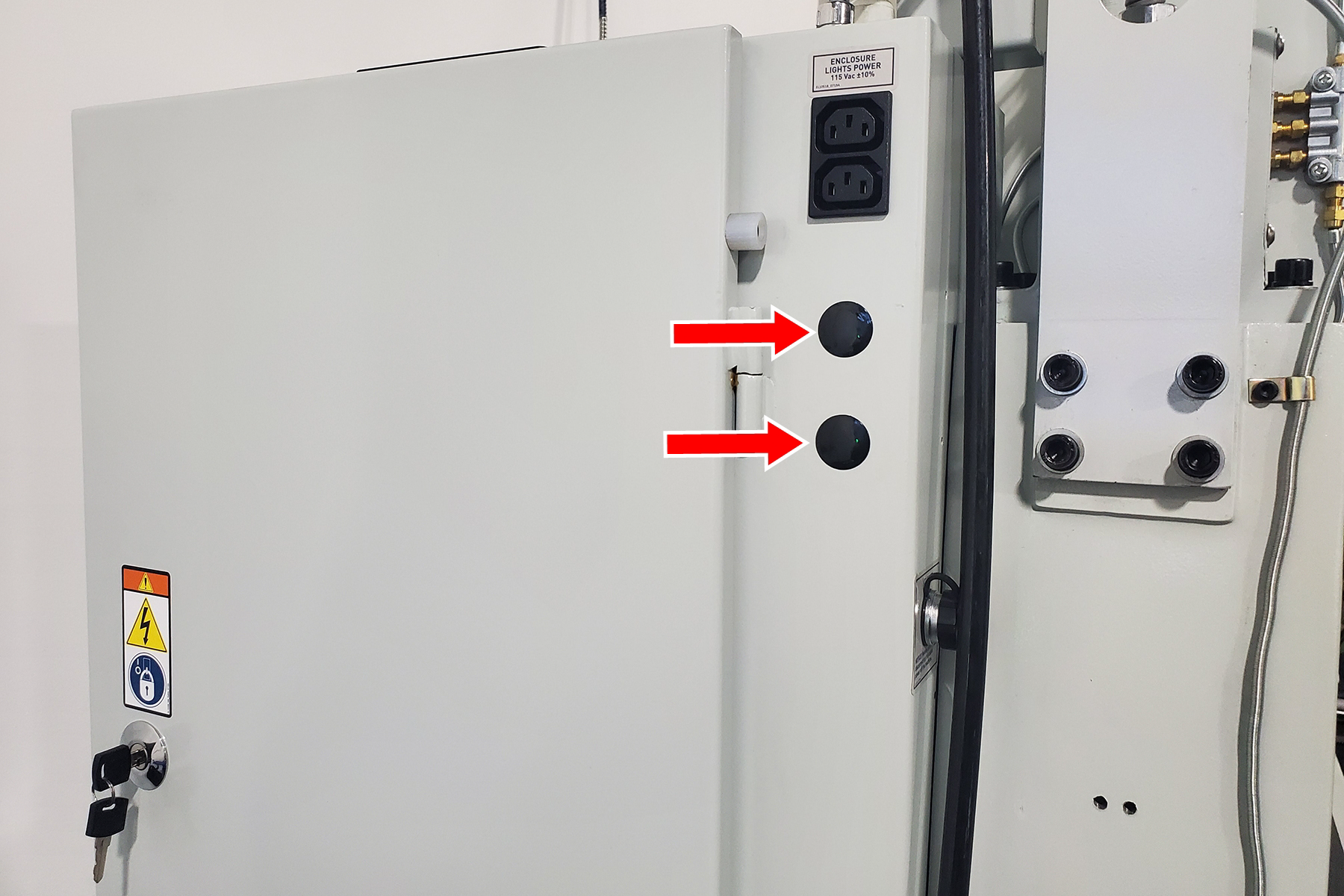
-
Place the cord grip into one of the knockout holes, and secure it in place.
-
Strip approximately 3 ft of the insulation from the end of the power cord to expose the individual wires.
-
Crimp ferrules onto the stripped ends of the power cord, and onto each end of the 16 gauge wire.
-
Label the wires as follows:
|
Wire |
Label |
|---|---|
|
16 gauge wire (both ends) |
109 |
|
Black wire of power cord |
130 |
|
Green wire of power cord |
GND17 or PE |
|
Blue wire of power cord |
102 N (770M/M+/MX)
|
-
Pass the power cord through the cord grip, ensuring a snug fit.
Make Electrical Connections
770M/M+/MX
-
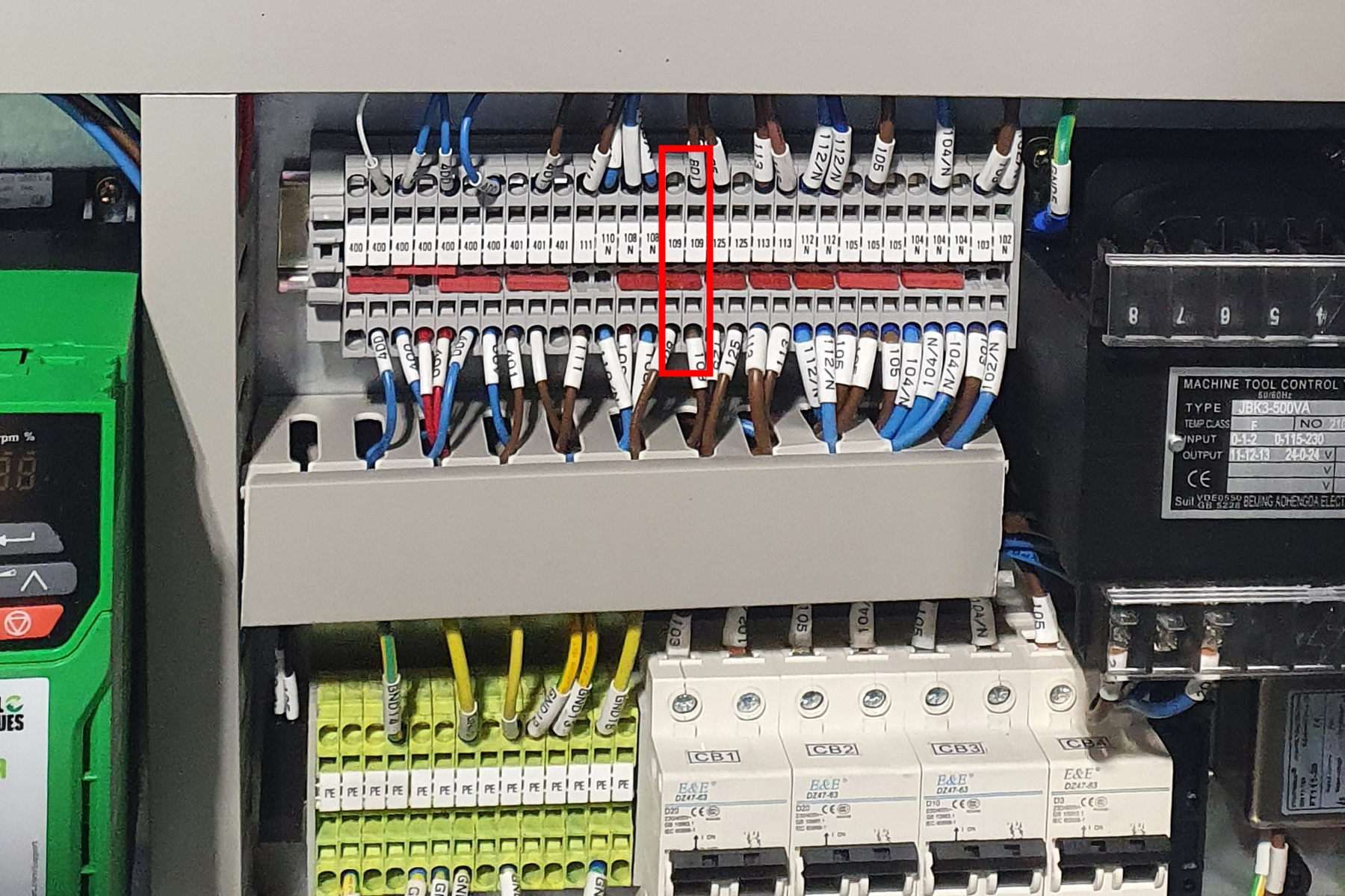
Locate the 109 terminal blocks between the green PE terminal blocks and the circuit breakers.
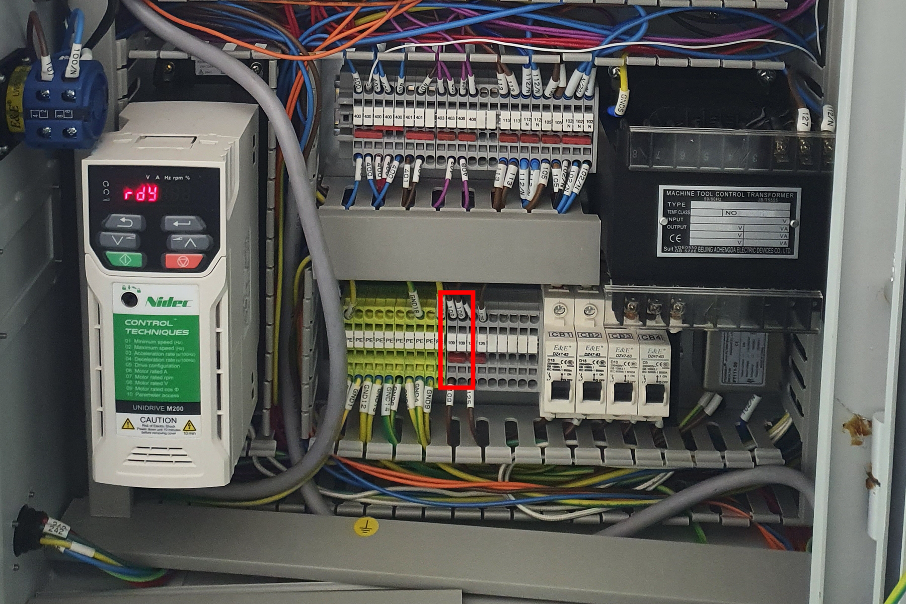
-
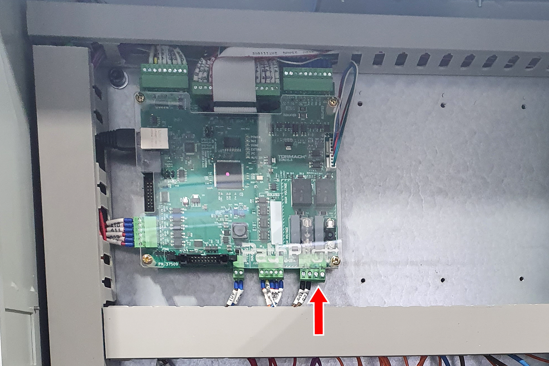
Connect one end of wire 109 (the 16 gauge wire) to the open terminal block position under the “109” label. Run the other end of the wire to J5.3 of the ECM board.
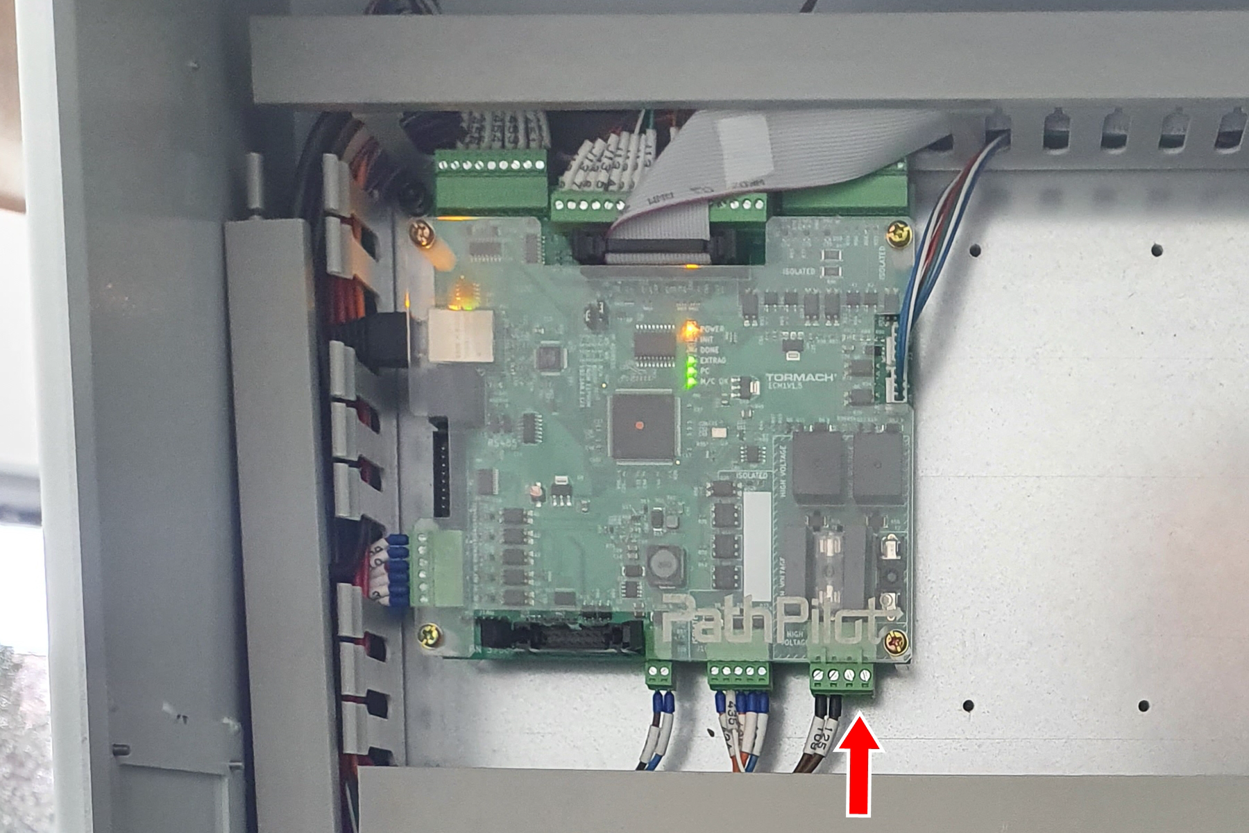
-
Connect wire 130 (the black wire of the power cord) into J5.4 of the ECM board.
-
Connect wire GND17/PE (the green wire of the power cord) into any open terminal block labeled “PE”.
-
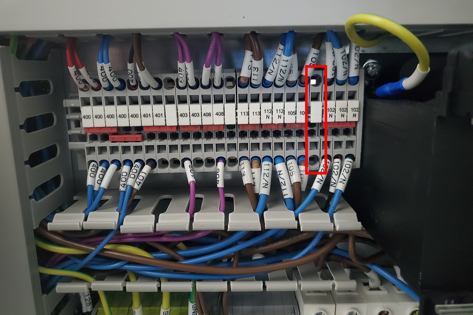
Locate the empty terminal blocks between the terminal blocks labeled “408” and “113”. Remove one of the empty terminal blocks from the DIN rail.
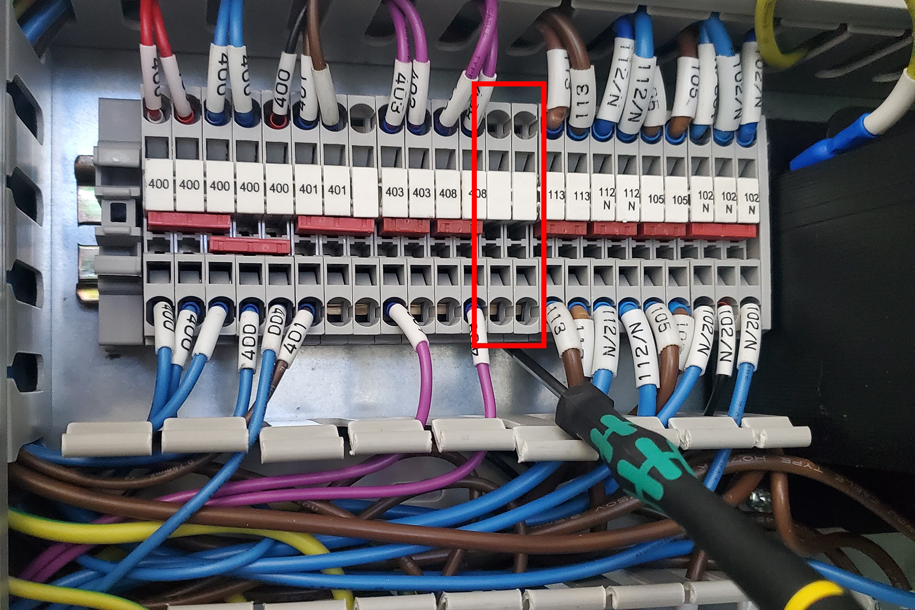
-
Slide all of the terminal blocks to the left of the “102 N” terminal blocks to the left to make space for the empty terminal block. Insert the empty terminal block on the left side of the “102 N” terminal blocks.
-
Remove the 3-position red jumper from the “102 N” terminal blocks, and insert the 4-position red jumper across the three “102 N” terminal blocks and the newly inserted terminal block.
-
Insert wire 102 N (the blue wire of the power cord) into one of the positions of the newly inserted terminal block.
1100M/M+/MX
-
Locate the 109 terminal blocks above the green PE terminal blocks and the circuit breakers.
-
Connect one end of wire 109 (the 16 gauge wire) to the open terminal block position under the “109” label. Run the other end to J5.3 of the ECM board.
-
Insert wire 130 (the black wire of the power cord) into J5.4 of the ECM board.
-
Insert wire GND17/PE (the green wire of the power cord) into any open terminal block labeled “PE”.
-
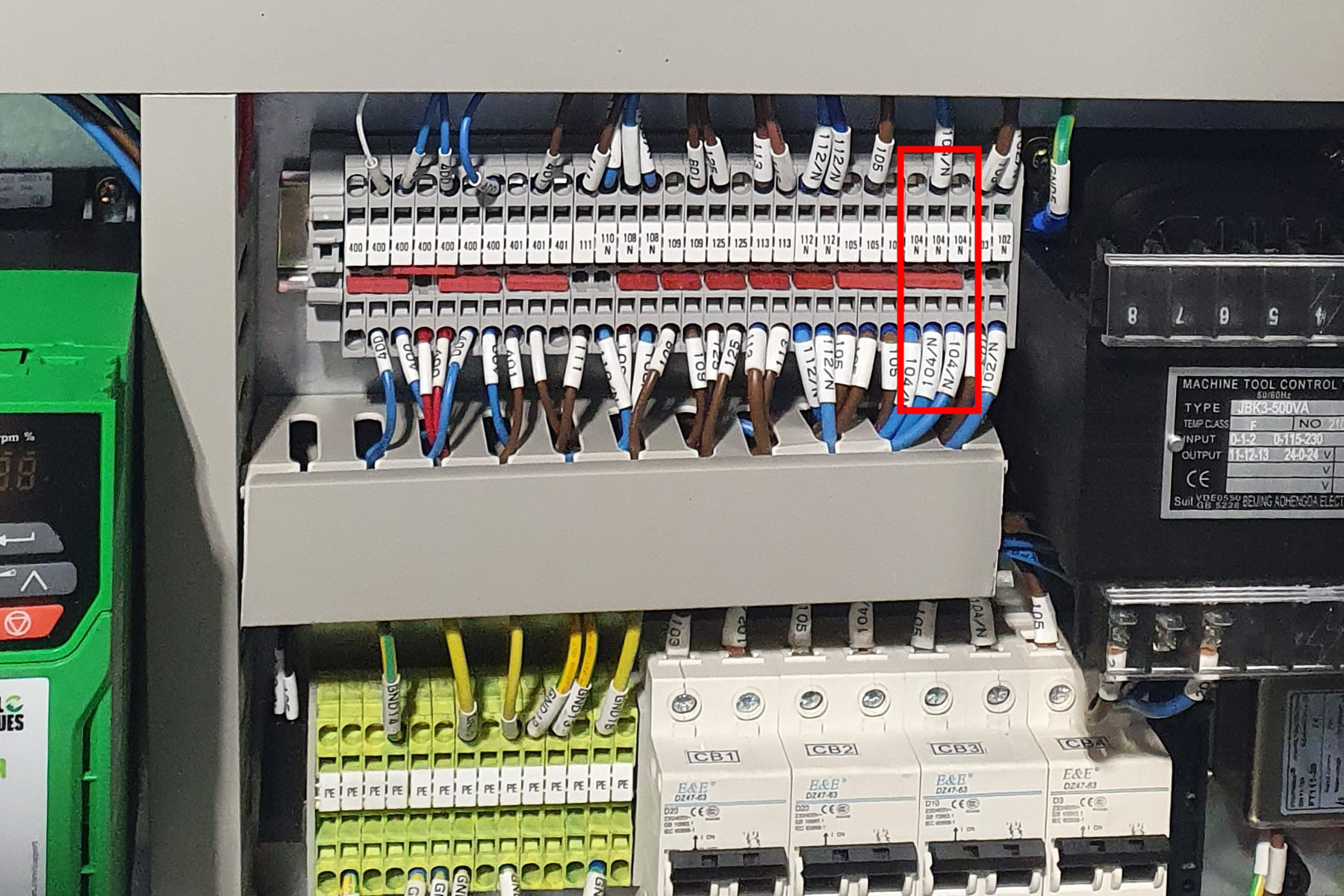
Locate the 104 N terminal blocks, and insert wire 104 N (the blue wire of the power cord) into the terminal block.
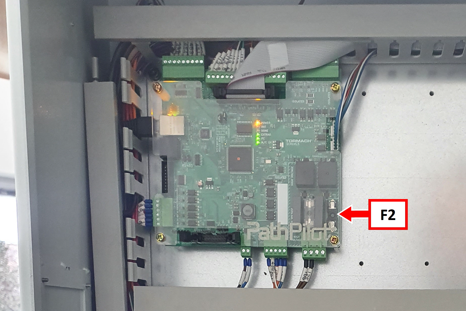
Install Fuse F2
-
Install a 3 A fuse into the fuse holder labeled “F2” on the ECM board.
Verify the Installation
-
Insert the leads of a multimeter into the L and N (outside) terminals of the power cord's socket. Set the multimeter to read 120v AC (770M/M+/MX) or 220v AC (1100M/M+/MX). When the machine is off, the meter should read 0v AC (770M/M+/MX) or 120v AC (1100M/M+/MX).
-
Power on the machine and the PathPilot controller.
-
Insert the power plug(s) into the wall outlet. If your system is hardwired, restore power to the circuit breaker(s).
-
Turn the Main Disconnect switch to ON on the side of the electrical cabinet.
-
Twist out the machine’s red Emergency Stop button, which enables movement to the machine axes and the spindle.
-
Press the Reset button.
-
Bring the machine out of reset and reference it.
-
-
Ensure you have PathPilot v2.10.0 or later.
-
From the PathPilot interface, select Mist Coolant. The button’s green LED illuminates.
-
Check the reading of your multimeter. The meter should read 120v AC (770M/M+/MX) or 220v AC (1100M/M+/MX).