Purpose
This document gives instructions on installing and configuring the Door Lock Switch Kit on a mill.
Product Information
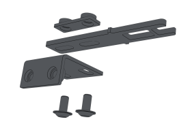
Product: Door Lock Switch Kit (PN 38283)
|
Quantity |
Description |
|
7 |
Screw, Button Head Cap (Flanged), M5 × 0.8 - 10, Stainless Steel (PN 38205) |
|
4 |
Screw, Button Head Cap, M5 × 0.8 - 50 (PN 39134) |
|
3 |
Cable Tie Anchor, Screw Mount, M5 (PN 31460) |
|
3 |
Cable Tie, 4 in., Nylon, Black (PN 31719) |
|
1 |
Door Switch (PN 37352) |
|
1 |
Lock Key (PN 37529) |
NOTE: If any items are missing, we can help. Create a support ticket with Tormach Technical Support at tormach.com/how-to-submit-a-support-ticket for guidance on how to proceed.
Required Tools
This procedure requires the following tools. Collect them before you begin.
-
Flat-blade screwdriver
-
Metric hex wrench set
-
Phillips screwdriver
Setup
Complete the following steps in the order listed:
Install the Door Lock Switch Kit
-
Power off the machine and the PathPilot controller.
-
Push in the machine's red Emergency Stop button, which removes power to motion control.
-
From the PathPilot interface, select Exit.
-
Turn the Main Disconnect switch to OFF on the side of the electrical cabinet.
-
-
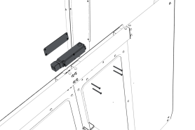
Attach the door switch to the door switch installation plate on the right enclosure door with a 3 mm hex wrench and four M5 × 0.8-50 button head screws.
-
Loosely attach the lock key and the lock key nut to the lock key bracket with a 3 mm hex wrench and two M5 × 0.8-10 flanged button head screws. You'll make further adjustments later in this procedure.
-
Loosely attach the lock key bracket assembly to the left enclosure door with a 3 mm hex wrench and two M5 × 0.8-10 flanged button head screws. You'll make further adjustments later in this procedure.
-
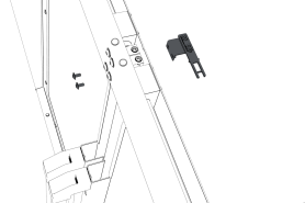
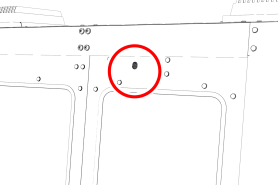
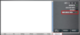
Identify the door lock override switch, as shown in the following image.
-
Remove the screw that secures the door lock override switch with a Phillips screwdriver, and then set it aside.
-
Turn the door lock override switch to the unlocked position with a flat-blade screwdriver.
-
Open and close the enclosure doors to align the door switch and the lock key. Make sure that the lock key freely engages and disengages the door switch.
-
Tighten all four M5 × 0.8-10 flanged button head screws on the lock key assembly.
-
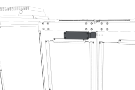
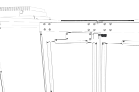
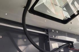
Attach two cable tie anchors to the right top panel on the enclosure with a 3 mm hex wrench and three M5 × 0.8-10 flanged button head screws.
-
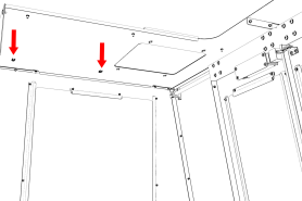
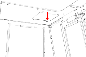
Attach the remaining cable tie anchor to the enclosure light's screw, as shown in the following image.
-
Route the loose end of the door switch cable to the electrical cabinet, and connect it to the Enclosure Door Switch outlet.
-
Secure the door switch cable to the cable tie anchors that you installed with three cable ties. Make sure that the cable doesn't restrict the motion of the enclosure door. Wind any remaining cable in to a coil, and secure it to the cable tie anchor closest to the Enclosure Door Switch outlet.
-
Turn the door lock override switch to the locked position with a flat-blade screwdriver.
-
Find the screw for the door lock override switch that you set aside in Step 6. Then, put it back to secure the door lock override switch in the locked position.
-
Power on the machine and the PathPilot controller.
-
Turn the Main Disconnect switch to ON on the side of the electrical cabinet.
-
Twist out the machine's red Emergency Stop button, which enables movement to the machine axes and the spindle.
-
Press the Reset button.
-
Bring the machine out of reset and reference it.
-
Update PathPilot
Before using the Door Lock Switch Kit, you must make sure that the PathPilot controller is updated to PathPilot v2.1.6 (or newer). This version of PathPilot has settings required to use the Door Lock Switch Kit.
To update PathPilot, do either of the following:
Download and Install an Update File from the Controller
-
Confirm that the PathPilot controller is powered on and out of Reset mode.
-
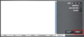
Downloading and installing an update file requires an Internet connection. From the Status tab, confirm that the Internet button LED light is on. Then, select Update.

-
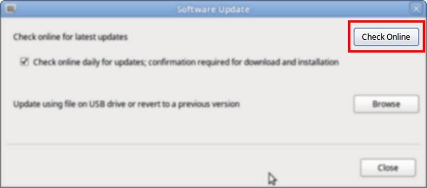
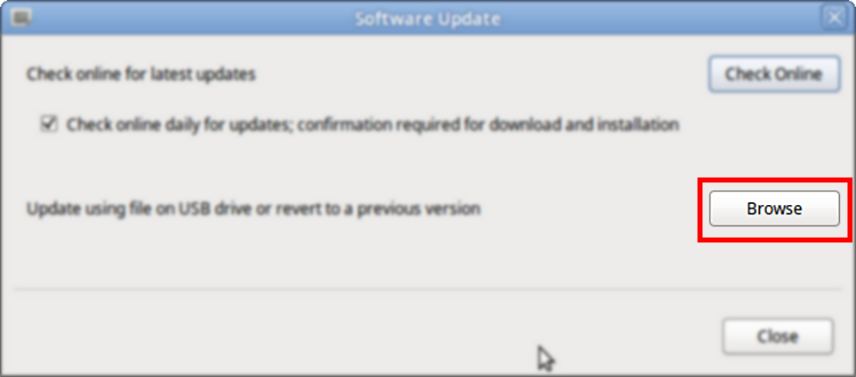
From the Software Update dialog box, select Check Online.
-
Select Install.
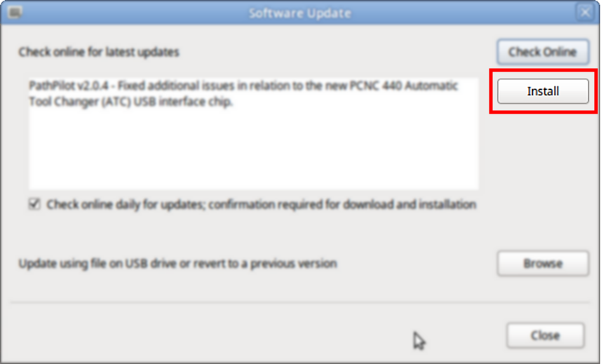
The update file is downloaded, and a notification dialog box displays.
-
From the dialog box, select OK.
The update file is installed on the PathPilot controller. -
Follow the on-screen instructions to restart the PathPilot controller.
Install an Update File from a USB Drive
-
From the PathPilot support center, download the most recent PathPilot update file.
-
Transfer the PathPilot update file to a USB drive.
-
Put the USB drive into the PathPilot controller.
-
Confirm that the PathPilot controller is powered on and out of Reset mode.
-
From the Status tab, select Update.
-
From the Software Update dialog box, select Browse.
-
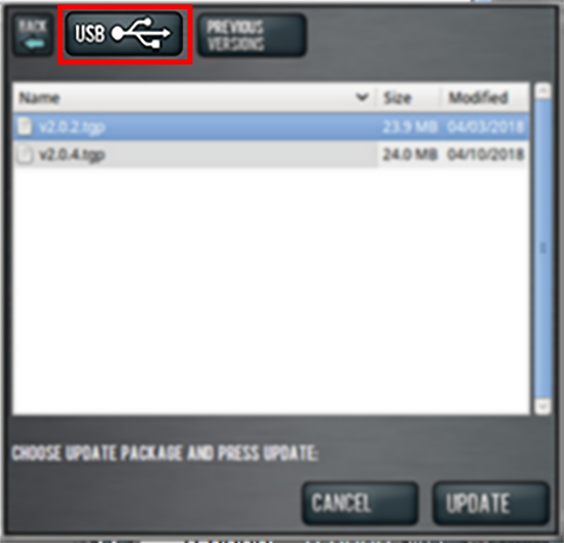
From the Browse dialog box, select USB.
-
Select the desired update file, and then select Update.
The update file is installed on the PathPilot controller. -
Follow the on-screen instructions to restart the PathPilot controller.
Enable the Door Lock Switch Kit
Supported with:


If you have a Door Lock Switch Kit, you must first enable it in PathPilot.
To enable the Door Lock Switch Kit:
-
On the Settings tab, select Enclosure Door Switch.
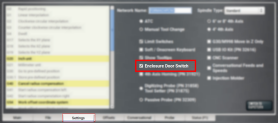
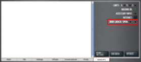
On the Status tab, the Door Locked / Open LEDs display.
-
Reference the machine: select Ref Z, Ref X, and Ref Y.
-
Open the enclosure doors.
-
From the PathPilot interface, on the Status tab, make sure that the Door Open LED is on, and the Door Locked LED is off.
-
Close the enclosure doors and verify that the Door Open LED is off. Then, push in the Emergency Stop button on the operator box.
The doors lock, and the Door Locked LED comes on. -
From the PathPilot interface, on the Status tab, make sure that the Door Open LED is off.
-
Unlock the enclosure doors: twist out the Emergency Stop button and press the Reset button on the operator box.
The doors unlock.
Operation
While using a Door Lock Switch Kit, you must close the enclosure doors before selecting Cycle Start. After you select Cycle Start, the doors lock and stay locked until any of the following occur:
-
A manual tool change is required.
-
From the PathPilot interface, you select Feedhold.
-
From the PathPilot interface, you select Stop or Reset.
-
The program reaches an M00 or M01 break.
-
The program completes and stops.
When you push in the Emergency Stop button on the operator box, the doors lock and stay locked until you twist out the Emergency Stop button and press the Reset button.
Read the following sections to understand how to operate the Door Lock Switch Kit:
Change the Maximum Spindle Speed
By default, the spindle speed reduces to 1000 RPM (or the speed at which the spindle is programmed, if it's less than 1000 RPM), and all axis motion stops when the enclosure doors are opened. Once you close the doors, the spindle resumes to its programmed speed, but axis motion isn't resumed until you select Cycle Start.
To change the maximum spindle speed:
-
From the PathPilot interface, in the MDI Line DRO field, type ADMIN OPENDOORMAXRPM [MAXIMUM SPINDLE SPEED].
Example
To set the maximum spindle speed to 500 RPM, type ADMIN OPENDOORMAXRPM 500. To stop the spindle, type ADMIN OPENDOORMAXRPM 0.
Use the Door Lock Override Switch
If the enclosure doors are locked and you need to manually open them, you can use the door lock override switch.
To use the door lock override switch:
-
Identify the door lock override switch, as shown in the following image.

-
Remove the screw that secures the door lock override switch with a Phillips screwdriver, and then set it aside.
-
Turn the door lock override switch to the unlocked position with a flat-blade screwdriver.
To view a PDF version of your manual, go to Tormach document TD10573.
If you have additional questions, we can help. Create a support ticket with Tormach Technical Support at tormach.com/how-to-submit-a-support-ticket for guidance on how to proceed.